


MANUAL NO: U30007
OWNER'S MANUAL
FOR
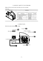
WIRE FEEDER
MODEL: CM-741U 1U30007
DO NOT
DESTROY
IMPORTANT: Read and understand the entire contents of this
manual, with special emphasis on the safety material throughout
the
manual,
before
installing,
operating,
or
maintaining
this
equipment. This equipment and this manual are for use only by
persons trained and experienced in the safety operation of welding
equipment. Do not allow untrained persons to install, operate or
maintain this equipment. Contact your distributor if you do not
fully understand this manual.
DAIHEN Corporation
WELDING PRODUCTS DIVISION
June22, 2011
Upon contact, advise MODEL and MANUAL NO.
4-1-063-2


