


IMPORTANT NOTE:
DAR models are suitable for Upflow and Horizontal
Installations only. Do not use for Downflow Installations.
IOD-4010
6/2013
INSTALLATION INSTRUCTIONS
Our continuing commitment to quality products may mean a change in specifications without notice.
© 2013
5151 San Felipe St., Suite 500, Houston, TX 77056
www.daikincomfort.com
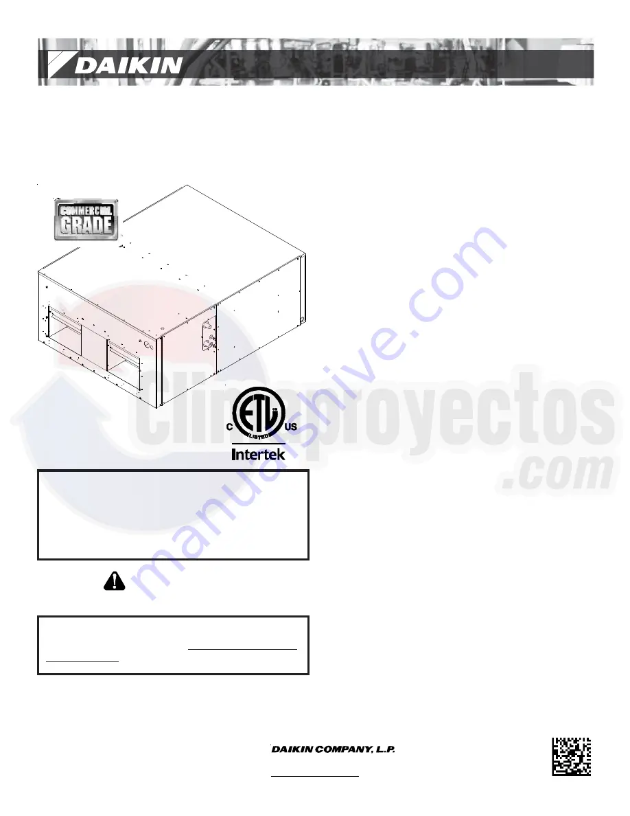
DAR
SERIES
COMMERCIAL AIR HANDLERS
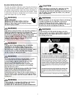
ATTENTION INSTALLING PERSONNEL:
Prior to installation, thoroughly familiarize yourself with this
Installation Manual. Observe all safety warnings. During
installation or repair, caution is to be observed.
It is your responsibility to install the product safely and to
educate the customer on its safe use.
RECOGNIZE THIS SYMBOL
AS A SAFETY PRECAUTION.
Index
Important Safety Instructions .............................................. 2
Product Identification .......................................................... 3
Product Description ............................................................. 3
Unit Inspection .................................................................... 3
Codes & Regulations ............................................................ 3
Replacement Parts ............................................................... 3
Pre-Installation Instructions ................................................. 3
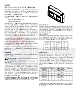
Location ............................................................................... 4
Ductwork ............................................................................. 4
Supply Ductwork and Flanges ............................................ 4
Return Ductwork ............................................................... 4
Return Air Filters ............................................................... 4
Electric Heat ........................................................................ 4
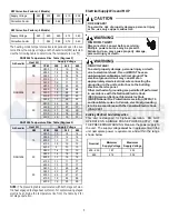
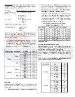
Electrical Supply Wire and MOP ........................................... 5
Building Electrical Service Inspection ................................. 5
Wire Sizing ........................................................................ 6
Maximum Overcurrent Protection (MOP) .......................... 6
Conversion 0f 460 Electrical Power Supply ......................... 7
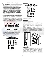
Electrical Connections .......................................................... 7
Supply Voltage .............................................................. 7
Air Handler Only (Non-Heat Kit Models) ....................... 7
Heater Kit Models ......................................................... 7
Low Voltage Connections .............................................. 8
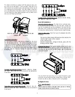
Heat Kit Installation ............................................................. 8
Refrigerant Lines .................................................................. 8
Tubing Preparation ........................................................... 9
Post Brazing ...................................................................... 9
Piping Size ......................................................................... 9
Evaporator Coil TXV ........................................................... 10
Airflow ............................................................................... 10
Belt Tension ....................................................................... 10
Regular Maintenance ......................................................... 11
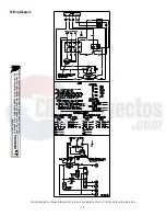
Wiring Diagram .................................................................. 12


