background image


Service Manual

- Gas boiler
          - EHYKOMB33AA / EHYKOMB33AA

- Hydro-box
          - EHYHBH05AAV3 / RHYHBH05AAV3
          - EHYHBH08AAV3 / RHYHBH08AAV3
          - EHYHBX08AAV3 / RHYHBX08AAV3

- Outdoor unit
          - EVLQ05CAV3 / RVLQ05CAV3
          - EVLQ08CAV3 / RVLQ08CAV3

Hybrid

ESIE13-02

Summary of Contents for ESIE13-02

Page 1: ...e Manual Gas boiler EHYKOMB33AA EHYKOMB33AA Hydro box EHYHBH05AAV3 RHYHBH05AAV3 EHYHBH08AAV3 RHYHBH08AAV3 EHYHBX08AAV3 RHYHBX08AAV3 Outdoor unit EVLQ05CAV3 RVLQ05CAV3 EVLQ08CAV3 RVLQ08CAV3 Hybrid ESIE...

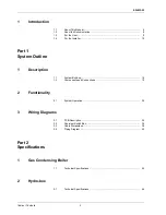
Page 2: ...stem Outline 1 Description 1 1 System Build up 18 1 2 Components and Connections 19 2 Functionality 2 1 System Operation 22 3 Wiring Diagrams 3 1 PCB Description 32 3 2 Overview Switch Box 34 3 3 Cabl...

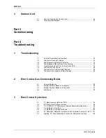
Page 3: ...1 7 Overview of the Outdoor Safety Devices 83 1 8 Overview of the Hydro box Safety Devices 84 2 Error Codes Gas Condensing Boiler 2 1 General Guidelines 85 2 2 Solving Problems Based on Symptoms 86 2...

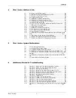
Page 4: ...Gas Shortage Malfunction 139 5 2 U2 Abnormal Power Supply Voltage 141 5 3 U3 Underfloor Heating Screed Dry out Failure 143 5 4 U4 Malfunction of Transmission between Hydro box and Outdoor Unit 144 5 5...

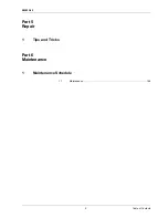
Page 5: ...ESIE13 02 5 Table of Contents 3 4 5 1 Part 5 Repair 1 Tips and Tricks Part 6 Maintenance 1 Maintenance Schedule 1 1 Maintenance 168...

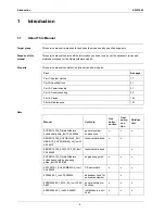
Page 6: ...ooting 53 Part 5 Repair 165 Part 6 Maintenance 167 Manual Contents Gas boiler section Heat pump sec tion Outdoor unit ECPEN13 729_Daikin Altherma hybrid heat pump_tcm135 285966 general system explanat...

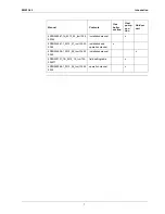
Page 7: ...1_2013_07_tcm135 29 0386 installation and operation manual x 4PEN344906 1_2013_02_tcm135 29 0349 installation manual x 4PEN353731_1B_2013_10_tcm135 304271 field setting table x 4PEN349588 1_2013_05_t...

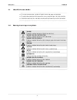
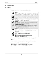
Page 8: ...t could result in electrocution DANGER RISK OF BURNING Indicates a situation that could result in burning because of extreme hot or cold tem peratures WARNING Indicates a situation that could result i...

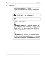
Page 9: ...gislation Units must be treated at a specialized treatment facility for reuse recycling and recovery By ensuring this product is disposed of correctly you will help to prevent potential negative conse...

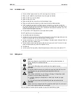
Page 10: ...or approved by Daikin WARNING Make sure installation testing and applied materials comply with applicable legisla tion on top of the instructions described in the Daikin documentation CAUTION Wear ade...

Page 11: ...s where there is a risk of fire due to the leakage of flammable gases example thinner or gasoline carbon fibre ignitable dust In places where corrosive gas example sulphurous acid gas is produced Corr...

Page 12: ...have a high total hardness 3 mmol l sum of the calcium and magnesium concentrations calculated as calcium carbonate Using filling water and top up water which does NOT meet the stated quality requirem...

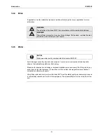
Page 13: ...condition shall be installed in the fixed wiring WARNING ONLY use copper wires All field wiring must be performed in accordance with the wiring diagram supplied with the product NEVER squeeze bundled...

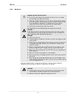
Page 14: ...meter or regulator and pipe work to the meter MUST be checked preferably by the gas supplier This is to ensure that the equipment works good and meets the gas flow and pressure requirements 1 4 8 Gas...

Page 15: ...lues and Ventilation for gas appliances of rated input NOT exceeding 70 kW Part 1 Flues BS 5440 Flues and Ventilation for gas appliances of rated input NOT exceeding 70 kW Part 2 Air Supply BS 5546 20...

Page 16: ...Introduction ESIE13 02 16 3 1 4 5...

Page 17: ...IE13 02 17 Part 1 System Outline 4 3 4 5 1 Part 1 System Outline What is in this part This part contains the following chapters Chapter See page 1 Description 18 2 Functionality 22 3 Wiring Diagrams 3...

Page 18: ...or space heating and domestic hot water Depending on the position of the 3 way valve the gas condensing boiler can either be bypassed or not The heat pump can either operate or not depending on the ac...

Page 19: ...ion with the accompanying elbow in flue sets c Sensor S1 m Connection block terminal strip X4 d Sensor S2 n Condensate drain pan e Fan o Hot water sensor S3 f Flow sensor p Condensate S3 g Space heati...

Page 20: ...02 Part 1 System Outline 20 3 1 1 4 5 1 2 2 Hydro box Item Description a Gas in b Cold water in c Refrigerant gas connection d Refrigerant liquid connection e Heating return f Heating flow g Hot water...

Page 21: ...IE13 02 Description 21 Part 1 System Outline 3 1 4 5 1 2 3 Outdoor unit Item Description a Terminal strip with earth terminal b Gas stop valve 15 9 CuT c Service port d Liquid stop valve 6 4 CuT a b c...

Page 22: ...eration 2 1 1 Heating Mode Heat pump only operation The heat pump and pump are enabled the gas boiler is bypassed Space heating is enabled Allowable outdoor temperature range 25 to 25 C a Outdoor unit...

Page 23: ...y 23 Part 1 System Outline 3 1 4 5 SP 2 SP 1 SP SP 1 SP 2 0 1 0 1 Time HEATPUMP MODE heatpump operation boiler operation at highest setpoint set in weather dependent or 60 C if fixed heating water tem...

Page 24: ...1 1 4 5 Hybrid operation mode The heat pump pump and gas boiler are enabled Space heating is enabled Allowable outdoor temperature range 25 to 25 C a Outdoor unit b Indoor unit c Plate heat exchanger...

Page 25: ...ESIE13 02 Functionality 25 Part 1 System Outline 3 1 4 5 SP 2 SP 1 SP SP 1 SP 2 0 1 0 1 Time HYBRID MODE heatpump operation boiler operation room temperature...

Page 26: ...nabled It works alternating depending on the demand of domestic hot water If there is a domestic hot water demand the unit stops serving the heating and turns in domestic hot water mode Allowable outd...

Page 27: ...estic hot water only mode The heat pump and the pump are idle the gas boiler is enabled Space heating is disabled It works alternating depending on the demand of domestic hot water a Outdoor unit b In...

Page 28: ...on demand Both can happen parallel During hybrid operation the system will automatically switch one or both units to ON for heating accordantly to the settings in ecological economical domestic hot wa...

Page 29: ...er operation return temp inlet temp heatpump operation defrosting hysteresis of 10 C Return temperature below 18 C 0 0 1 1 Time NOT DURING DEFROST start up of heatpump mode return 15 C heatpump operat...

Page 30: ...mp leaving water will drop below setpoint due to capacity shortage of the heatpump Economical mode capacity shortage Equilibrium point operation of the equilibrium point is independant of ecological o...

Page 31: ...n temperature and ambient temperature The energy prices are set by the user or installer and can be adjusted Ecologic When the heat pump operates at the break even COP the primary energy use to produc...

Page 32: ...er controller e Fuse 3 15 A T f Gas valve and ignition unit g Ionisation ignition probe h Main voltage i Fan S1 Flow sensor S2 Return sensor S3 Domestic hot water sensor S5 Flow switch S7 Space heatin...

Page 33: ...ESIE13 02 Wiring Diagrams 33 Part 1 System Outline 3 1 4 5 3 1 2 External connection diagram For more details check unit wiring diagram...

Page 34: ...PART 1 fulfil the following functions S1S Preferential kWh rate can force the outdoor heat pump to switch off S2S Electric power meter pulse input for the purpose of energy metering S3S Gas meter puls...

Page 35: ...pplied by PCB X5 Switch box Switch box Gas pulse meter input 5 V DC pulse detection voltage supplied by PCB 7 8 A4P SS1 ON OFF 1 2 A3P only for solar option 13a X2M 21 28 29 Alarm output Space C H On...

Page 36: ...supplied from outdoor Only for preferential kWh rate power supply outdoor Use normal kWh rate power supply for indoor unit Shut off valve DHW pump output Max load 2 A inrush 230 V AC 1 A continuous H2...

Page 37: ...mestic hot water pump M2S 2 way valve for cooling mode M3S 3 way valve for floor heating domestic hot water tank M4S Bypass valve gas boiler PHC1 Optocoupler input circuit PS Switching power supply Q...

Page 38: ...y line to the outdoor unit Cable type 230 V 20 A C 230 V 3G 2 5 35m 3G 4 75m A 3 1 A 8 1 all Hybrid Types Voltage Cable type Voltage Cable type Voltage Cable type Voltage Cable type Voltage Cable type...

Page 39: ...nal if 7 connected 2 A 1 P X39A X2M 8 9 10 Electric meter cabinet optional A4P pcb Alarm or Solar optional X 5M 5 6 user interface if 1 then X6YA X6Y disconnect and connect X6YB X6Y X 1 M 1 2 3 A1P X9...

Page 40: ...heating water out 3 Shut off valve with drain fill valve field installation 4 Expansion vessel 5 Filter 6 Pump 7 Plate heat exchanger 8 Air purge 9 Flow sensor 10 3 way valve 11 Safety valve 12 Boiler...

Page 41: ...E13 02 41 Part 2 Specifications 4 3 4 5 2 Part 2 Specifications What is in this part This part contains the following chapters Chapter See page 1 Gas Condensing Boiler 42 2 Hydro box 44 3 Outdoor Unit...

Page 42: ...CH Min Max 80 60 kW 7 9 31 9 Efficiency CH NCV 80 60 98 Efficiency CH NCV 40 30 30 107 Heating power DHW Min Max kW 7 9 31 9 Efficiency DHW NCV 105 Casing Colour RAL9010 Dimensions Unit Height x width...

Page 43: ...setting L and 2x with opened casing 8 6 9 6 9 8 10 8 Gas supply pressure mBar 20 30 25 35 gas metering ring mm HRE36 30 6 95 5 25 Minimum rpm of max parameter d 25 40 Minimum start rpm of max paramete...

Page 44: ...xchanger Type Brazed plate Qty 1 Water volume l 0 9 1 3 Water flow rate min l min 5 0 11 0 Insulation material Green felt Green felt Elastomeric foam Expansion vessel Volume l 10 Max water pressure ba...

Page 45: ...o box 45 Part 2 Specifications 4 3 4 5 2 Operation range heat pump oper ation Outdoor tempera ture Space cooling C 10 43 Space heating heat pump C 25 25 Water tempera ture Space cooling C 5 22 Space h...

Page 46: ...units Condition 1 Indoor H P module EHYHBH05 EHYHBH08 EHYHBX08 Heating capacity Minimum kW 1 80 1 80 1 80 Nominal kW 4 40 7 40 7 40 Maximum kW 5 12 10 02 10 02 Cooling capacity Minimum kW 2 50 Nomina...

Page 47: ...weight ERLQ004 ERLQ006 ERLQ008 kg 57 59 Packing Material EPS CARTON Weight kg 3 Heat exchanger Specifications Length mm 845 N of rows 2 Fin pitch mm 1 8 N of stages 32 Tube type Hi Xa 8 Fin Type WF fi...

Page 48: ...lve electronic type N of circuits 1 Refrigerant oil Type FVC50K Charged volume l 0 75 Piping connec tions Liquid Type Flare connection Diameter OD mm 6 35 Gas Type Flare connection Diameter OD mm 15 9...

Page 49: ...ase by support backup heater Range increase by support booster heater or backup heater 2 The sound pressure level is measured via a microphone at a certain distance from the unit It is a relative valu...

Page 50: ...Outdoor Unit ESIE13 02 Part 2 Specifications 50 3 1 2 5...

Page 51: ...ESIE13 02 51 Part 3 Commissioning 4 3 4 5 3 Part 3 Commissioning See Note on page 6...

Page 52: ...ESIE13 02 Part 3 Commissioning 52 3 1 3 5...

Page 53: ...s in this part This part contains the following chapters Chapter See page 1 Troubleshooting 54 2 Error Codes Gas Condensing Boiler 85 3 Error Codes Hydro box 94 4 Error Codes Outdoor Units 103 5 Error...

Page 54: ...tive thermostat 27 1 Internal leak of the 4way valve No substantial difference between suction and discharge temperature 27 2 Unsatisfactory compression from the compressor 27 3 Different kind of refr...

Page 55: ...button the error code and a brief description of the error will be shown A short list of all errors and corrective actions can be found in the installer reference guide More detailed information on ho...

Page 56: ...compressor Defective remote controller Troubleshooting Caution Be sure to turn off power switch before connect or disconnect connector or parts damage may be occurred Is thermostat changed and reset...

Page 57: ...Compressor does not Applicable model ERHQ011 016 ERLQ004 016 Error detection method Error generating condition Supposed causes Faulty thermistor Faulty indoor outdoor unit PC board Faulty magnetic sw...

Page 58: ...voltage output from the PC board YES YES Hydro box pump runs at set flow rate Hydro box PC board Outdoor unit PC board Relay 1 Output from magnetic switch or U V W of power transistor 2 Output from ma...

Page 59: ...ndition Supposed causes Excess charge of refrigerant Air intrudes into refrigerant system Faulty pressure switch Faulty magnetic switch for outdoor unit fan motor Faulty aux relay for outdoor unit fan...

Page 60: ...ant system Faulty pressure switch Is there any item disturbing air waterflow Is the heat exchanger soiled Is the remote controller displaying the t symbol NO NO YES NO YES YES Hydro box flow error Hyd...

Page 61: ...ion thermostat Overcurrent relay may act due to the following reasons Lower voltage of power supply Excess level of high pressure Insufficient size of power cable Malfunction of compressor Compressor...

Page 62: ...een inlet and outlet of expansion valve Is there any temperature difference between suction side and discharge side of four way valve Turn the operation switch ON and OFF then wait at ON side Check on...

Page 63: ...roduces Loud Noise or Shakes Applicable model ERHQ011 016 ERLQ004 016 Error detection method Error generating condition Supposed causes Faulty installation Excess charge of refrigerant Air intrudes in...

Page 64: ...oes the pipe contact with casing Is the noise flushing sound from pressure reducing valve or capillary tube Correction of installation Reinforcement for ceilings or walls Insert shock absorber in moun...

Page 65: ...Supposed causes Troubleshooting Caution Be sure to turn off power switch before connect or disconnect connector or parts damage may have occurred Check the unit based on hydro box LED and outdoor uni...

Page 66: ...Check that all shut off valves of the water circuit are completely open Check if the water filter needs cleaning Make sure there is no air in the system purge air Check on the manometer that there is...

Page 67: ...start up out of its operation range the water temperature is too low In case of low water temperature the system uti lizes the backup heater to reach the minimum water temperature first 18 C Check tha...

Page 68: ...n There is air in the system Purge air Water pressure at pump inlet is too low Check on the manometer on the unit that there is sufficient water pressure The water pressure must be 1 5 bar Check that...

Page 69: ...tection method Error generating condition Supposed causes corrective action Possible causes Corrective action The expansion vessel is broken Replace the expansion vessel The water volume in the instal...

Page 70: ...Possible causes Corrective action Dirt is blocking the water pressure relief valve outlet Check for correct operation of the pressure relief valve by turning the red knob on the valve coun ter clockwi...

Page 71: ...creen is not visible Check if there is a tank connected Then setting A 2 2 1 should be set to yes The RT screen is not visible Check setting A 2 1 to see if unit control method is set to Room Thermost...

Page 72: ...01 and domestic hot water shall be covered supported by the electrical heater To guarantee sufficient domestic hot water and reasonable domestic hot water heat up times 2 The applicable Ta can be dete...

Page 73: ...eating operation at low Ta equilibrium temperature status backup heater allowance 5 00 and equilib rium temperature 5 01 are not set or not opti mized according to the site application 1 Optimize the...

Page 74: ...on the average heat emitter surface temperature The average heat emitter surface temperature is determined by the temperature difference between the inlet and outlet water temperature of the heat emi...

Page 75: ...nction code plus a short description of the error is displayed when pushing the t button on the user interface In case of a warning the unit will continue operation In case of an error the unit will p...

Page 76: ...Manual Reset in the Memory Explanation In order to reset the malfunction code in the remote controller memory follow actions has to be performed Remark For some malfunction codes it s required to man...

Page 77: ...an motor lock or outdoor fan instantaneous overcurrent malfunction E9 Malfunction of electronic expansion valve outdoor unit F3 Discharge pipe temperature malfunction outdoor unit H3 Failure of high p...

Page 78: ...utdoor unit or Gas shortage Transmission between hydro box and outdoor unit is not being carried out correctly or There is very little or no refrigerant flow within the hydro box U5 Failure of transmi...

Page 79: ...ration halts due to malfunction depending on the model or condition 2 Troubleshoot by turning off the power supply for a minimum of 5 seconds turning it back on and then rechecking the LED display Mic...

Page 80: ...80 Return water temperature thermistor abnormality 96 81 Leaving water temperature thermistor abnormality 96 89 PHE freeze up protection control 95 7H Water flow abnormality 97 AH Tank disinfection f...

Page 81: ...sensor system 121 J1 Malfunction of pressure sensor 122 J3 Malfunction of discharge pipe temperature sensor system 121 J5 Suction pipe thermistor malfunction 121 J6 Malfunction of heat exchanger tempe...

Page 82: ...ce Page U0 Gas shortage 139 U2 Abnormal power supply voltage 141 U3 Underfloor heating screed dry out error 143 U4 or UF Transmission error between hydro box and outdoor unit 1 144 UF Malfunction of t...

Page 83: ...eshooting 83 Part 4 Troubleshooting 4 3 4 5 4 1 7 Overview of the Outdoor Safety Devices High pressure switch Fuse Open Close ERHQ011 016BA 4 0 MPa 0 0 15 3 0 0 15 6 3A 250V ERLQ CA 4 17 MPa 0 0 15 3...

Page 84: ...11l min in hp operation If 3V BUH min 12l min If 9W BUH min 15l min AD120120 Protector Clixon Cut out condition Reference EKSWW Q2L 85 C 3 C 4SW03476 1 EKSWWU Q2L 85 C 3 C 4SW03476 1 Q3L 85 C 3 C EKHW...

Page 85: ...the mains Turn off the respective circuit breaker When a safety device was activated stop the unit and find out why the safety device was activated before resetting it NEVER bridge safety devices or c...

Page 86: ...Error Codes Gas Condensing Boiler ESIE13 02 Part 4 Troubleshooting 86 3 1 4 5 2 2 Solving Problems Based on Symptoms Not available at this moment...

Page 87: ...nd indicates them on the display by error codes If the LED is flashing the controller has detected a problem Once the problem is rectified the controller can be restarted by pressing the f button Foll...

Page 88: ...of gas valve 6 Flame detection fault Replace ignition cable and spark plug cap Replace ignition unit Replace boiler controller 8 Incorrect fan speed Fan catching on casing Wiring between fan and casi...

Page 89: ...ontact the gas company No No ignition Yes Replace ignition pin No No spark Ignition unit on gas block faulty Yes Check the cabling Check the spark plug cap Replace the ignition unit No Gas air adjustm...

Page 90: ...n gap No Gas air adjustment not correctly set Yes Check the setting See gas air adjust ment No Weak spark Yes Check the ignition gap Replace the ignition pin Replace the ignition unit transformer on t...

Page 91: ...S1 or S2 faulty Yes Replace sensor S1 or S2 See fault code temperature display 1 or 2 No Burner does not ignite Yes See burner does not ignite Possible causes Corrective action Heat pump error Check t...

Page 92: ...sary Temperature is too low Increase the space heating temperature No circulation in the installation Check whether there is circulation At least 2 or 3 radiators MUST be open The boiler power has NOT...

Page 93: ...high Adjust the inlet assembly Temperature setting for water circuit is too low Set the hot water circuit on the heat pump user interface depending on the desired tempera ture No heat transfer as a r...

Page 94: ...r or externally and usually requires more voltage for erasure than the common 5 volts used in logic circuits It functions like non volatile RAM but writing to EEPROM is slower than writing to RAM Supp...

Page 95: ...box heat exchanger temperature is below 0 C during cooling operation Supposed causes Detection error due to faulty hydro box heat exchanger thermistor Detection error due to faulty hydro box PCB Trou...

Page 96: ...han 120 ohms or below about 50 C more than 1 860 kOhms Note The values vary slightly in some models Supposed causes Faulty connector connection Faulty thermistor Faulty PCB Troubleshooting CJ Room tem...

Page 97: ...ds Supposed causes Closed shut off valve Air in the system Clogged water filter Insufficient water pressure Too high external static pressure pump speed setting Malfunction of hydro box pump Hydro box...

Page 98: ...tional water to the system No No No No Yes No No No No Purge the water circuit Open the airpurge valve Is the water filter clogged dirty External static pressure is in range of the hydro box pump rang...

Page 99: ...asure the resistance value on the connector of the flow sensor At a restart of the system the pump will operate for 15 seconds before error code occurs Use these 15 seconds to confirm the voltages of...

Page 100: ...urs Supposed causes Malfunction of the flow sensor Water flow caused by external source Troubleshooting 1 Do not disconnect the connector of the flow sensor on the PCB X4A Measure the voltage value on...

Page 101: ...function of the domestic hot water tank thermistor R5T Incorrect parameters on the solar pump station Troubleshooting 1 Confirm the maximum allowed tank temperature via solar panels in the installatio...

Page 102: ...function is not completed correctly Either tank temperature for disinfection A 4 4 4 is not reached or temperature is not kept for required time A 4 4 5 Supposed causes Disinfection function was inter...

Page 103: ...Faulty outdoor unit PCB Troubleshooting Caution Be sure to turn off power switch before connect or disconnect connector or parts damage may be occurred Turn the power supply off once and then back on...

Page 104: ...the high pressure switch is actuated Actuating pressure Supposed causes Faulty high pressure switch Disconnection in high pressure switch harness Faulty connection of high pressure switch connector C...

Page 105: ...PS Correct the high pressure Replace the outdoor unit PC board A1P ERHQ V3 ERLQ V3 Replace the inverter PC board A2P ERHQ W1 ERLQ W1 Replace the high pressure switch HPS NO YES Connect correctly Are c...

Page 106: ...unction decision conditions In cooling When the detection pressure is the following value 0 12 MPa or less continues for 5 minutes When the saturated pressure equivalent to the detection temperature i...

Page 107: ...normal refer to 2 Is the heat exchanger distribution pipe thermistor connector X12A properly connected to the outdoor PC board Is the pressure sensor connector X17A properly connected to the A1p PC bo...

Page 108: ...isconnect connector or parts damage may be occurred Outdoor unit PC board A1P GND 5V Pressure sensor X17A Microcomputer A D input 2 Measure voltage here 4 3 2 1 Red Black White V2809 Output voltage V...

Page 109: ...d compressor and detects the position signal pattern Malfunction decision conditions The position signal with 3 times cycle as imposed frequency is detected when compressor motor operates normally but...

Page 110: ...YES NO NO Is high pressure higher than 2 6 MPa at starting YES NO Check and see whether compressor is short circuited or ground YES Are inverter output voltages the same for 3 phases Does low or high...

Page 111: ...n decision conditions When the fan runs with speed less than a specified one for 15 seconds or more when the fan motor running conditions are met When connector detecting fan speed is disconnected Whe...

Page 112: ...thin the normal range Turn OFF the power again and wait for 10 minutes Remove the fan motor connector Is the supply voltage within the range 180 to 220 VAC NO YES Properly connect the connector NO YES...

Page 113: ...external factor noise etc other than unit failure may be a cause of the malfunction Properly plug the fan motor connector and then turn ON the power again Is the fan motor normal NO YES Is the fuse c...

Page 114: ...emperature thermistor Malfunction decision conditions When the following conditions are met for 10 minutes Suction pipe superheat degree 4 C Minimum electronic expansion valve opening degree Connector...

Page 115: ...he coil resistance of the electronic expansion valve normal 2 YES NO YES Are the characteristics of each thermistor normal 3 Are the pressure sensor characteristics normal 4 NO YES NO Is the temperatu...

Page 116: ...operation Refer to Check 13 14 15 to eliminate the causes of wet operation It is believed that factors noise etc other than failure caused the malfunction Replace the outdoor PC board A1P ERHQ V3 ERL...

Page 117: ...ding to the temperature detected by the discharge pipe temperature sensor Malfunction decision conditions When the discharge pipe temperature rises to an abnormally high level When the discharge pipe...

Page 118: ...l Is the discharge pipe thermistor correctly connected to PCB A1P Is the discharge pipe temperature high 115 C Is the discharge pipe thermistor attached to the discharge pipe Abnormality in refrigeran...

Page 119: ...device circuit checks continuity in the high pressure switch Malfunction decision conditions When there is no continuity in the high pressure switch during compressor stops operating Supposed causes...

Page 120: ...ating then check the following Connect correctly Replace the lead wire Replace the outdoor unit PC board A1P ERHQ V3 ERLQ V3 Replace the inverter PC board A2P ERHQ W1 ERLQ W1 Is there continuity in ea...

Page 121: ...4 Resistance Conversion Table Ambient Coil Fin on page 153 Caution Be sure to turn off power switch before connect or disconnect connector or parts damage may be occurred YES YES NO Check connectors...

Page 122: ...ure 0 05MPa continues 185 s Supposed causes Faulty pressure sensor Faulty outdoor unit PC board Incorrect connection of connector Troubleshooting Is the relation between the pressure and the voltage n...

Page 123: ...disconnect connector or parts damage may be occurred Outdoor unit PC board A1P GND 5V Pressure sensor X17A Microcomputer A D input 2 Measure voltage here 4 3 2 1 Red Black White V2809 Output voltage V...

Page 124: ...eration at the time of startup Detect malfunctions using an MP PAM series capacitor overvoltage sensor Malfunction decision conditions When over current is detected at the time of waveform output befo...

Page 125: ...the fan motor Is the power supply voltage between 180 and 220 VAC NO YES Connect tightly and correctly Is the lead wire for compressor connected to PC board and compressor without becoming loose NO Re...

Page 126: ...ected by the thermistor of the radiation fin Malfunction decision conditions When the temperature of the inverter radiation fin increases abnormally due to faulty heat dissipation Supposed causes Acti...

Page 127: ...e Troubleshooting P4 Can it be considered that the fin temperature was high 1 NO YES Connect correctly Is the connector of the fin thermistor correctly connected to the outdoor PC board 1 YES Continue...

Page 128: ...er transistor into voltage with CT1 DC current sensor Malfunction decision conditions When overcurrent has run to power transistor Actuated even by instantaneous overcurrent Supposed causes Faulty com...

Page 129: ...supply voltage Is the inverter output voltage generated approximately at the same increasing speed for each phase after turning on again 1 U V V W W U Open the stop valve Replace the compressor Repla...

Page 130: ...etected by converting the current flowing to power transistor into voltage with CT1 DC current sensor Inverter PC board detects the disorder of position signal Malfunction decision conditions When com...

Page 131: ...istor IGBT Is the continuity normal YES NO NO YES NO When operating compressor with compressor output line disconnected the compressor stops due to malfunction after elapsed time of 5 seconds Therefor...

Page 132: ...onverting the current flowing to power transistor into voltage with CT1 DC current sensor Inverter PC board detects the disorder of position signal Malfunction decision conditions When compressor over...

Page 133: ...ain U V V W W U Continuity check in the power transistor IGBT Is the continuity normal Is the stop valve open Check the installation conditions NO YES NO YES NO YES When operating compressor with comp...

Page 134: ...er transmission between control and inverter PC board is carried out normally Malfunction decision conditions When the transmission is not carried out in a specified period of time or longer Supposed...

Page 135: ...splayed Are connectors connecting the control and inverter PC board connected securely Disconnect the fan motor connector and turn on again Connect the transmission wiring and turn on again Connect th...

Page 136: ...lance between phases Faulty outdoor inverter PC board Faulty main circuit capacitor Power unit Disconnection in diode module Faulty magnetic relay K11R K12R Improper main circuit wiring Troubleshootin...

Page 137: ...oor unit PC board Troubleshooting See also Check No 4 Resistance Conversion Table Ambient Coil Fin on page 153 Caution Be sure to turn off power switch before connect or disconnect connector or parts...

Page 138: ...lfunction decision is made only when turning the power supply on Supposed causes Improper set value of E2PROM Improper capacity setting adaptor Faulty outdoor unit PC board Troubleshooting Capacity se...

Page 139: ...l of suction air superheating high pressure indoor heat exchanger temperature and indoor suction air temperature Malfunction decision conditions In cooling operation When compressor frequency does not...

Page 140: ...ch before connect or disconnect connector or parts damage may be occurred Check the inter unit wiring and piping between the indoor and outdoor units NO YES YES Is the refrigerant level proper NO Matc...

Page 141: ...in the inverter and power supply voltage drop for V3 only 150 170 VAC or when the power failure of several tons of ms or longer is generated or DC voltage is not in range of 305 380 VDC for W1 only 3...

Page 142: ...f power switch before connect or disconnect connector or parts damage may be occurred Is the power supply voltage between 220 240 VAC 10 Check LED on outdoor unit PC board Is the voltage insufficient...

Page 143: ...end user Supposed causes Another error U3 only generated when other error is solved Operation OFF button pushed Power failure Troubleshooting Check if dry out schedule was interrupted If schedule was...

Page 144: ...are off it indicates that the transmission wiring between indoor and outdoor units may be incorrect or broken disconnected NO YES Is the power supply voltage between 180 and 220 VAC YES NO NO NO Wire...

Page 145: ...he indoor PC board There is no problem with the unit An external factor noise etc other than unit failure may be the cause Is the resistance value of the outdoor fan motor normal NO YES YES YES NO Doe...

Page 146: ...quid thermistor R3T and the indoor suction air thermistor R1T B Difference in evaporation temperature Te or condensation temperature Tc during heating operation detected by the indoor heat exchanger t...

Page 147: ...ring between the indoor and outdoor units is incorrect Does UF appear when the power is turned ON NO YES YES Match the connection of the inter unit wiring and piping between the indoor and outdoor uni...

Page 148: ...de cause noise Connection of two master remote controllers when using two remote controllers Troubleshooting Caution Be sure to turn off power switch before connect or disconnect connector or parts da...

Page 149: ...ty of X14A for AB models Troubleshooting Caution Be sure to turn off power switch before connect or disconnect connector or parts damage may be occurred Model E 01 value EHB VH X004CA 0 EHB VH X008CA...

Page 150: ...location No Clean the heat exchanger No Change the installation location or direction No Yes Yes Check the spaces for all air passage around the suction and discharge areas Check the outdoor ambient...

Page 151: ...power ON to check whether the expansion valve is producing a clicking sound 5 Check the coil current Open circuit normal short circuit 6 Check the clicking sound again If Then The expansion valve has...

Page 152: ...tor R1T A2P Ambient sensor user interface R1T A3P Ambient sensor ON OFF thermistor R2T Outlet water after BUH thermistor R2T External sensor floor or ambient R3T Refrigerant liquid thermistor R4T Inle...

Page 153: ...62 4 70 4 54 4 38 4 23 4 08 3 94 3 81 3 68 3 56 10 111 99 108 96 30 16 10 15 76 70 3 50 3 44 9 8 7 6 5 4 3 2 1 106 03 100 41 95 14 90 17 85 49 81 08 76 93 73 01 69 32 103 18 97 73 92 61 87 79 83 25 7...

Page 154: ...nk thermistor is for EKHWS B and EKHWE domestic hot water tanks The relationship between normal temperature and resistance is shown in the graph and the table below Tank thermistor for EHV CA domestic...

Page 155: ...74 0 76 0 78 0 33 7 31 4 29 2 27 2 142 0 144 0 146 0 148 0 3 9 3 7 3 5 3 3 10 0 478 8 80 0 25 4 150 0 3 2 12 0 14 0 16 0 18 0 432 9 392 0 355 3 322 4 82 0 23 7 152 0 154 0 156 0 158 0 3 0 2 9 2 7 2 6...

Page 156: ...or unit installed under such conditions that short circuit easily occurs Visual inspection Is the piping length 5 meters or less Visual inspection Does air enter the refrigerant system Conduct refrige...

Page 157: ...If YES the check valve is caught Is the LPS normal Check continuity using a tester Is the hydro box installed under such conditions that short circuit easily occurs Visual inspection Is the refrigeran...

Page 158: ...due to adherent contamination etc Replace the expansion valve 2 Accumulator Frosting Choked moisture Blow a nitrogen gas and then replace the refrigerant 3 Distributor Temperature difference Dust Chok...

Page 159: ...the contact terminal on the harness side with the connector connected 7 Disconnect the connector X107A with the power supply OFF and Operation OFF 8 Is the voltage between pins 4 and 3 of X107A about...

Page 160: ...g wind the condenser is charged and electric shock may result Therefore disconnect the connector from the outdoor unit fan motor after con firming that the outdoor unit fan has stopped 4 Before measur...

Page 161: ...ion superheat degree further increases In addition because the compressor frequency drops to the level of the lowest frequency 52 Hz and the refrigerant flow rate decrease low pressure cannot be maint...

Page 162: ...ing operating conditions Diagnosis of excessive refrigerant charging In cooling operation 1 Because high pressure rises due to excessive charging overload control is carried out and capacity tends to...

Page 163: ...Operation Note Reference values for superheat degree to be used in the judgement of wet operation 1 Suction pipe superheat degree 4 C or more 2 Discharge pipe superheat degree 5 C or less The values a...

Page 164: ...performance must be adjusted Normal operation PWM model Pump in standby Normal operation Blinks red green Pump in function but stopped Pump restarts by itself after the fault is disap peared 1 Underv...

Page 165: ...ESIE13 02 165 Part 5 Repair 4 3 4 5 5 Part 5 Repair What is in this part This part contains the following chapters Chapter See page 1 Tips and Tricks 166...

Page 166: ...Tips and Tricks ESIE13 02 Part 5 Repair 166 3 1 5 5 1 Tips and Tricks Not available at this moment...

Page 167: ...ESIE13 02 167 Part 6 Maintenance 4 3 4 5 6 4 Part 6 Maintenance What is in this part This part contains the following chapters Chapter See page 1 Maintenance Schedule 168...

Page 168: ...dealer 4 Pressure relief valve hose Check that the pressure relief valve hose is positioned appropriately to drain the water If the optional drain pan kit is installed make sure that the pressure reli...

Page 169: ...quired Fitted Not Required Fitted Not Required Provided Quantity litres No Yes No Yes ft3 hr Gas Inlet Pressure OR OR mbar m3 hr mbar OR OR m3 hr mbar C C Yes Yes Yes Yes Yes Yes ft3 hr Gas inlet Pres...

Page 170: ...No Comments Service 2 Date Signature Engineer Name Company Name Telephone No Gas Safe Register No Comments Service 3 Date Signature Engineer Name Company Name Telephone No Gas Safe Register No Comment...

Reviews: