background image


WATER-COOLED SCREW CHILLER 
 
MICROTECH III and MICROTECH 4


REV 

02 

Date 

05/2021 

Supersedes  D

–EOMWC00A07-16_01EN 

CONTROL PANEL OPERATING MANUAL 

D

–EOMWC00A07-16_02EN 

Summary of Contents for MicroTech III

Page 1: ...WATER COOLED SCREW CHILLER MICROTECH III and MICROTECH 4 REV 02 Date 05 2021 Supersedes D EOMWC00A07 16_01EN CONTROL PANEL OPERATING MANUAL D EOMWC00A07 16_02EN...

Page 2: ...S 17 7 1 CALCULATIONS 17 7 2 UNIT MODEL 17 7 3 UNIT ENABLE 17 7 4 UNIT MODE SELECTION 17 7 5 UNIT CONTROL STATES 18 7 6 UNIT STATUS 19 7 7 ICE MODE START DELAY 19 7 8 EVAPORATOR PUMP CONTROL 19 7 9 CO...

Page 3: ...RCUIT RAPID STOP ALARMS 47 10 9 CIRCUIT PUMPDOWN STOP ALARMS 57 10 10 CIRCUIT EVENTS 60 11 BASIC CONTROL SYSTEM DIAGNOSTIC 63 12 USING THE CONTROLLER 65 12 2 NAVIGATING 66 13 OPTIONAL REMOTE USER INTE...

Page 4: ...r menu item accessible without password Then pressing the MENU key will return to the Menu screen WARNING Electric shock hazard can cause personal injury or equipment damage This equipment must be pro...

Page 5: ...he unit is enabled to run not necessarily running on a call for cooling and when the water temperature reaches a point of freeze possibility Two levels of security protection against unauthorized chan...

Page 6: ...the chiller The operator can monitor all critical operating conditions by using the screen located on the main controller In addition to providing all normal operating controls the MicroTech control...

Page 7: ...controller with a number of extension I O modules attached depending on the chiller size and configuration Up to two optional BAS communication modules may be included on request An optional Remote O...

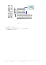
Page 8: ...trols architecture uses the following One Microtech main controller I O extension modules as needed depending on the configuration of the unit Optional BAS interface as selected Communication Cards BA...

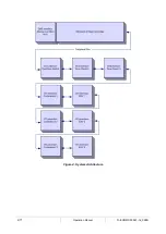
Page 9: ...9 77 Operation Manual D EOMWC00A07 16_02EN Figure 4 System Architecture...

Page 10: ...arine version Communication modules The new Microtech 4 has the possibility to offer Modbus RTU and Bacnet MSTP or IP communications integrated in the controller To activate this feature a specific pr...

Page 11: ...d via the Chiller Enable set point the unit status will be Off Keypad Disable If the chiller is enabled then the unit will be in the Auto state and the evaporator water pump output will be activated A...

Page 12: ...art next circuit Yes The second circuit will go through its start sequence at this point Note that a third circuit can be started if available The two preceding conditions must again be satisfied afte...

Page 13: ...tart Yes No The circuit must be enabled before it can run It may be disabled for several reasons When the circuit switch is off the status will be Off Circuit Switch If the BAS has disabled the circui...

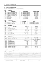
Page 14: ...1 Unit PVM Fault No Fault DI2 Evaporator Flow Switch No Flow Flow DI3 Double Set Point Mode Switch Cool mode Ice mode DI4 External Alarm Remote off Remote on DI5 Unit Switch Unit off Unit on DI6 Emerg...

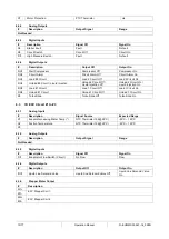
Page 15: ...2 Circuit On Liquid Injection On DO5 Load 1 Circuit Load 1 Circuit Off Load 1 Circuit On DO6 Unload 1 Circuit Unload 1 Circuit Off Unload 1 Circuit On X5 Turbo Slide Turbo Slide Off Turbo Slide On 6 3...

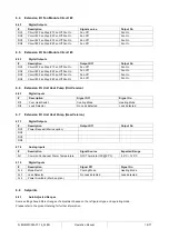
Page 16: ...ff Fan On 6 6 Extension I O Unit Heat Pump Old Version 6 6 1 Digital Inputs Description Signal Off Signal On DI1 Cool Heat Switch Cooling Mode Heating Mode DI2 Leak Detector No Leak detected Leak dete...

Page 17: ...ment that the BAS request must be on Unit is enabled according to the following table NOTE An x indicates that the value is ignored Unit Switch Control Source Set Point Remote Switch Input Unit Enable...

Page 18: ...ce w Glycol Heat Ice Network x x Heat Cool Ice w Glycol Heat Heat x x x Test Test 7 4 1 Glycol Configuration If the Available Modes Set Point is set to an option w Glycol then glycol operation is enab...

Page 19: ...Config Changed Reboot Unit State Off and Unit Enable Set Point Disable 19 Off Set Mfg Location Unit State Off and Unit Enable Set Point Disable 7 7 Ice Mode Start Delay An adjustable start to start ic...

Page 20: ...imary at this time 7 9 Condenser Pump Control There are three condenser pump control states for control of the condenser pump Off Start Pump is on water loop is being recirculated Run Pump is on water...

Page 21: ...llowing are true The unit state is auto EWT Cond In or LWT Cond Out is equal or higher than Tower fan Set point If the Condensation Control Value Set Point is set to Cond In or Cond Out options and Co...

Page 22: ...w Glycol BAS Ice Set Point Local OFF ON X HEAT Heat Set Point 1 Local ON ON X HEAT Heat Set Point 2 Network X x HEAT HEAT BAS Heat Set Point 7 11 2 Leaving Water Temperature LWT Reset The base LWT tar...

Page 23: ...ge Up Delta T set point When multiple compressors are running one will shut down if evaporator LWT is lower than the target minus the Stage Down Delta T set point The last compressor running will shut...

Page 24: ...y 7 12 4 Staging Sequence This section defines which compressor is the next one to start or stop In general compressors with fewer starts will normally start first and compressors with more run hours...

Page 25: ...ty increase is not allowed within this deadband If unit capacity is above the deadband capacity is decreased until it is back within the deadband For 2 circuit units the deadband is 7 For 3 circuit un...

Page 26: ...greater than 75 load when the LWT exceeds the limit This feature is to keep the circuit running within the capacity of the condenser coil A dead band placed below the limit set point will be used to...

Page 27: ...ollowing equation Discharge superheat Discharge Temperature Condenser Saturated Temperature 8 1 5 Oil Differential Pressure Oil Differential Pressure is calculated for each circuit with this equation...

Page 28: ...does not rise above the unload set point and the circuit has been running longer than the Startup Time set point then the circuit is turned off and an alarm triggered If the evaporator pressure drops...

Page 29: ...set points These cycle timers are enforced even through cycling of power to the chiller These timers may be cleared via a setting on the controller Compressor Run Timer When a compressor starts a time...

Page 30: ...ng slide is moved by pulsing of the load and unload solenoids to achieve the required capacity An additional solenoid is controlled to assist in moving the modulating slide in certain conditions This...

Page 31: ...il the High Condenser Pressure Hold event has cleared See the Circuit Events section for details on triggering reset and unloading action 8 5 Pressure condensation control If the Condensation Control...

Page 32: ...rts The preopen position is defined by a set point The time allowed for this preopen operation is at least enough time for the EXV to open to the preopen position based on the programmed movement rate...

Page 33: ...ather than changing all at once This transition prevents the circuit from becoming unstable and resulting in a shutdown due to alarm trip 8 7 Liquid Injection Liquid injection is activated when the ci...

Page 34: ...he needs to contact the Daikin Personnel and asks for a new password As soon as the new password is communicated the follow steps allow the customer to change the Option Set by himself 1 Wait for the...

Page 35: ...cific Status Description 553489691893 Activate the Option Set for 3 Months 411486702597 Activate the Option Set for 1 Month 084430952438 Activate the Option Set for 1 Month Mode Permanent A permanent...

Page 36: ...pressor load number of fans on and compressor run time are also stored 10 2 Signaling Alarms The following actions will signal that an alarm has occurred 1 The unit or a circuit will execute a rapid o...

Page 37: ...on each phases not only with chiller not running but mainly with chiller running from minimum capacity up to full load capacity That s because voltage drop can occur from a certain unit cooling capac...

Page 38: ...uto 10 4 4 Evaporator Water Freeze Protect This alarm is generated to indicate that the water temperature entering or leaving has dropped below a safety limit Control tries to protect the heat exchang...

Page 39: ...he water temperatures with a proper instrument and adjust the offsets Wrong freeze limit setpoint The freeze limit has not been changed as a function of glycol percentage Reset Notes Local HMI Network...

Page 40: ...ring in the alarm log UnitOffExternalAlarm String in the alarm snapshot UnitOffExternalAlarm There is an external event that has caused the opening for at least 5 seconds of the port on the controller...

Page 41: ...These alarms will not stop the unit immediately but with a normal shutdown procedure 10 5 1 Evaporator Entering Water Temperature Sensor Fault This alarm is generated any time the input resistance is...

Page 42: ...ring in the alarm log UnitOffEvpWTempInvrtd String in the alarm snapshot UnitOffEvpWTempInvrtd Entering and leaving water temperature sensors are inverted Check cabling of the sensors on the unit cont...

Page 43: ...diagram Module is broken Check if LED are on and both green If BSP LED is solid red replace the module Check if power supply is ok but LEDs are both off In this case replace the module Reset Notes 10...

Page 44: ...OffEvpEntWTempSen String in the alarm snapshot UnitOffEvpEntWTempSen Sensor is broken Check for sensor integrity according table and allowed kOhm k range Check correct sensors operation Sensor is shor...

Page 45: ...is into allowed range Reset Notes Local HMI Network Auto Automatically clears when the signal returns in the allowed range 10 6 6 Bad Demand Limit Input This alarm is generated when the Demand Limit o...

Page 46: ...A or more than 21mA Check for values of input signal to the unit controller It has to be in the allowed mA range Check for electrical shielding of wirings Check for right value of the unit s controlle...

Page 47: ...lication Check the evaporator approach and the corresponding water temperature to evaluate the low pressure hold limit High Evaporator Approach Clean the evaporator Check the quality of the fluid that...

Page 48: ...stopped Bell icon is moving on controller s display String in the alarm list Cx OffStartFailEvpPrLo String in the alarm log Cx OffStartFailEvpPrLo String in the alarm snapshot Cx OffStartFailEvpPrLo A...

Page 49: ...the required water flow Dirty or partially blocked condenser coil Condenserless units Remove any obstacle Clean the condenser coil using soft brush and blower Dirty condenser heat exchanger Clean the...

Page 50: ...e required water flow Dirty or partially blocked condenser coil Condenserless units Remove any obstacle Clean the condenser coil using soft brush and blower Dirty condenser heat exchanger Clean the co...

Page 51: ...properly Check if the digital output operates correctly Liquid injection orifice is small Check if when the liquid injection solenoid is activated the temperature can be controlled between the limits...

Page 52: ...t Notes Local HMI Network Auto 10 8 8 High Motor Temperature This alarm indicates that the motor temperature has exceeded the maximum temperature limit for safe operations Symptom Cause Solution Circu...

Page 53: ...rotation Refrigerant circuit is empty of refrigerant Check circuit pressure and presence of refrigerant Not proper operation of evaporating or condensing pressure transducers Check proper operation o...

Page 54: ...Check if power supply is ok but LEDs are both off In this case replace the module Reset Notes Local HMI Network Auto 10 8 12 FC Comm Failure Circuit 2 or 3 This alarm is generated in case of communic...

Page 55: ...replace the module Reset Notes Local HMI Network Auto 10 8 14 Evaporator Pressure Sensor Fault This alarm indicates that the evaporating pressure transducer is not operating properly Symptom Cause So...

Page 56: ...sor electrical contacts Check for correct plug in of the electrical connectors Check for correct sensors wiring also according electrical scheme Reset Notes Local HMI Network Auto 10 8 16 Motor Temper...

Page 57: ...a proper operation Reset Notes Local HMI Network Auto 10 9 Circuit Pumpdown Stop Alarms 10 9 1 Low Discharge Superheat Fault This alarm indicates that the unit has worked for too long with low dischar...

Page 58: ...e gate rotors screw rotor for possible damages Check if the cooling tower or three way valves are operating correctly and properly set Reset Notes Local HMI Network Auto 10 9 3 Oil Pressure Sensor Fau...

Page 59: ...l connectors Check for correct sensors wiring also according with electrical scheme Reset Notes Local HMI Network Auto 10 9 5 Discharge Temperature Sensor Fault This alarm is generated to indicate tha...

Page 60: ...ooling to see if the charge is correct Protection limit not set to fit customer application Check the evaporator approach and the corresponding water temperature to evaluate the low pressure hold limi...

Page 61: ...nits The air temperature measured at the inlet of the condenser may not exceed the limit indicated in the operational range working envelope of the chiller Check the location where the unit is install...

Page 62: ...f the exv to the driver If the C and O LED blink alternatively the driver sees the motor as disconnected Check if any debris can hold the valve from moving Dismount the motor and check for scratches o...

Page 63: ...lid Green BSP running Solid Red Hardware Error Flashing Red BSP Error Solid Green Communication running I O working Solid Yellow Communication running parameter missing Solid Red Communication down Co...

Page 64: ...ication Solid Yellow Startup Solid Red BACnet Server down Automatically a restart after 3 seconds are initiated Bacnet IP BuS LED Mode Solid Green Ready for Communication The BACnet Server is started...

Page 65: ...e includes an up arrow to indicate there are lines parameters above the currently displayed line and or a down arrow to indicate there are lines parameters below the currently displayed items or an up...

Page 66: ...e wheel Repeat for the remaining three numbers The password will time out after 10 minutes and is cancelled if a new password is entered or the control powers down Other basic information and links ar...

Page 67: ...utton is repeated pressed the display continues to revert one page back along the current navigation path until the main menu is reached When the Menu Home Button is pressed the display reverts to the...

Page 68: ...gain has an arrow and is a link to a further menu Press the wheel and jump to the Temperatures menu which contains six lines of temperatures set points Scroll down to Cool LWT 1 and press the wheel to...

Page 69: ...twork Limit Value R Demand Limit Value R View Set Circuit Unit Mode R Control Source R W Current Limit Setpoint R W Status Settings Compressor Time Until Restart Scheduled Maintenance Alarms Time Unti...

Page 70: ...g Water Temp R Alarm Active Evap Entering Water Temp R Alarm Log Evaporator Delta T R Active Set Point R Scheduled Maintenance Outside Air Temperature R Next Maintenance Month Year R W Cool LWT Setpoi...

Page 71: ...e Remaining R Name R W Compressor 3 Cycle Time Remaining R Dev Instance R W Compressor 4 Cycle Time Remaining R UDP Port R W DHCP R W Alarms Actual IP Address R Alarm Active Actual Mask R Alarm Log Ac...

Page 72: ...W Compressor Status Settings view set circuit Status Circuit 1 Time Until Restart Circuit Status R Compressor 1 Cycle Time Remaining R Circuit Mode R W Compressor 2 Cycle Time Remaining R Circuit Capa...

Page 73: ...be ordered anytime after chiller shipment and mounted and wired on the job as explained on the following page The remote panel is powered from the unit and no additional power supply is required All v...

Page 74: ...D EOMWC00A07 16_02EN Operation Manual 74 77...

Page 75: ...er name and a password Enter the following credential to get access to the web interface User Name ADMIN Password SBTAdmin The Main Menu page will be displayed The page is a copy of the onboard HMI an...

Page 76: ...ver The new battery shall be placed in the proper battery holder which is highlighted in the following picture respecting the polarities indicated into the holder itself 16 ICM AND MASTER SLAVE The un...

Page 77: ...nt and the products and services presented therein Specification are subject to change without prior notice Refer to the data communicated at the time of the order Daikin Applied Europe S p A explicit...

Reviews: