background image

Catalogue/Engineering Data

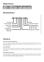
UAL-A Series Air Cooled Modular Chiller

Model: 

UAL160A5/UAL210A5

Refrigerant:

R410A

Cooling Capacity:

56/72kW

ED-UAL-A5-1603

DAIKIN INDUSTRIES., LTD.

Summary of Contents for UAL-A Series

Page 1: ...Catalogue Engineering Data UAL A Series Air Cooled Modular Chiller Model UAL160A5 UAL210A5 Refrigerant R410A Cooling Capacity 56 72kW ED UAL A5 1603 DAIKIN INDUSTRIES LTD ...

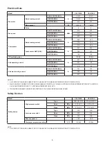
Page 2: ...Instruction 37 Error Code 41 Note Installation and maintenance are to be performed only by qualified personnel who are familiar with local codes and regulations and experienced with this type of equipment Caution Sharp edges and coil surfaces are a potential injury hazard Avoid contact with them Warning Moving machinery and electrical power hazard may cause severe personal injury or death Disconne...

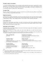
Page 3: ... made hermetic in the factory Customer do not need to connect any copper pioe or refill refrigerant or invest more money for complex water systems Outstanding Performance UAL R410A series features leading edge scroll technology and name brand accessories which are strictly tested for high compatibility and reliability Equipped with efficient scroll compressors and precise electronic expansion valv...

Page 4: ...sor minimizes the operation noise Intelligent Control System UAL R410A features user friendly intelligent control system Micro chip and large scaled LCD display are employed to make the control swift and easy Group control Optional One single controller can control a group made up by one master unit and maximum 9 slave units BMS Optional UAL R410A provides interfaces for BMS One serial port can su...

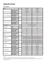
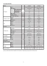
Page 5: ...0 1059 1853 72 42 73 2056 1140 2193 80 9 44 9 86 3 460V 3Ph 60Hz 1820 1059 1853 72 42 73 2056 1140 2193 80 9 44 9 86 3 380V 3Ph 60Hz 1820 1059 2012 72 42 79 2056 1140 2193 80 9 44 9 86 3 Packing dimensions L x W x H 208V 230V 3Ph 60Hz mm in 1820 1059 1853 72 42 73 2056 1140 2193 80 9 44 9 86 3 460V 3Ph 60Hz 1820 1059 1853 72 42 73 2056 1140 2193 80 9 44 9 86 3 380V 3Ph 60Hz 1820 1059 2012 72 42 79...

Page 6: ... 77 29 8 Condenser fan Type Drive Axial big vane and low noise blower Axial big vane and low noise blower Qty 2 2 Blade material Galvanized steel Galvanized steel Motor poles 6 8 Air volume m3 ft3 24000 13900 26000 15058 Compressor Type Scroll compressor Scroll compressor Qty 2 2 Refrigerant Type R410A R410A Charge kg 6 5 2 8 5 2 Flow control EXV EXV Numbers of circuits 2 2 Oil Model POE POE Charg...

Page 7: ... 50 Unit max running current 208V 230V 3Ph 60Hz A 79 1 103 460V 3Ph 60Hz 38 6 50 380V 3Ph 60Hz 49 1 65 NOTES 1 ALL SPECIFICTIONS ARE SUBJECTED TO CHANGE BY THE MANUFACTURER WITHOUT PRIOR NOTICE 2 MAX RUNNING CURRENT IS TESTED UNDER BELOW CONDITION COOLING OUTDOOR DRY BULB TEMPERATURE 43 C HEATING DRY BULB TEMPERATURE 21 C WET BULB TEMPERATURE 15 5 C 3 THE RATED RUNNING CURRENT ARE TESTED AT THE HI...

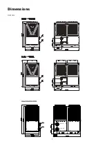
Page 8: ...7 Dimensions Unit mm WATER IN WATER OUT UAL WATER IN WATER OUT UAL UAL ...

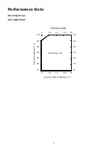
Page 9: ...mbient temperature leaving Ambiet temperature Leaving water temperature Operating Limit 10 15 15 leaving water temperature 5 7 5 10 12 5 15 30 40 40 Ambient temperature 20 25 35 30 operating limit 20 25 35 30 Cooling mode 5 48 10 7 5 15 12 5 48 21 0 5 5 10 15 H 30 26 Ambient temperature leavin Ambiet temperature Leaving water temperature Operating Limit Cooling mode Operating Limit Ambient tempera...

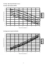
Page 10: ... 1 30 1 40 1 50 1 60 10 15 20 25 30 35 40 45 50 Ambient Temperature Crrection Factor of Capacity Leaving Water Temperature 5 6 7 9 12 15 g p 0 70 0 75 0 80 0 85 0 90 0 95 1 00 1 05 1 10 1 15 1 20 1 25 1 30 10 15 20 25 30 35 40 45 50 Ambient Temperature Crrection Factor of Power Leaving Water Temperature 5 6 7 9 12 15 g p ...

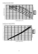
Page 11: ...7 9 12 15 Leaving Water Temperature C 0 70 0 75 0 80 0 85 0 90 0 95 1 00 1 05 1 10 1 15 1 20 1 25 1 30 10 15 20 25 30 35 40 45 50 Ambient Temperature C Crrection Factor of Capacity 5 6 7 9 12 15 Leaving Water Temperature C 0 70 0 75 0 80 0 85 0 90 0 95 1 00 1 05 1 10 1 15 1 20 1 25 1 30 10 15 20 25 30 35 40 45 50 Ambient Temperature C Crrection Factor of Capacity 5 6 7 9 12 15 Leaving Water Temper...

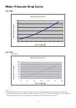
Page 12: ...e Drop Chart UAL210A5 Water pressure drop curve UAL160A5 UAL210A5 0 50 100 150 200 250 300 4 5 6 7 8 9 10 11 12 13 14 Water pressure drop kpa Water flow m3 h Water Pressure Drop Chart Water pressure drop curve UAL160A5 UAL210A5 0 50 100 150 200 250 300 4 5 6 7 8 9 10 11 12 13 14 Water pressure drop kpa Water flow m3 h Water Pressure Drop Chart NOTES 1 WATER PRESSURE DROP OF THE UNIT IS TESTED BY T...

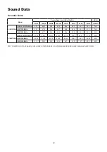
Page 13: ... 52 1 47 4 55 6 60 7 62 8 55 6 49 4 41 3 76 4 380V 3Ph 60Hz 41 6 47 7 54 4 56 0 59 6 53 9 46 6 38 1 66 8 UAL210A5 208V 230V 3Ph 60Hz 43 26 55 21 63 27 63 24 65 18 61 53 54 61 47 55 69 9 460V 3Ph 60Hz 35 28 51 38 60 79 64 28 64 33 61 98 56 9 49 26 69 9 380V 3Ph 60Hz 51 2 55 2 61 6 63 4 64 7 61 2 57 50 5 69 5 TEST CONDITION OCTAVE BAND LEVEL NOISE IS TESTED BASE ON 15DB A BACKGROUND NOISE SEMI ANECH...

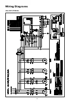
Page 14: ...13 Wiring Diagrams 208 230V 3Ph 60Hz ...

Page 15: ...14 ...

Page 16: ...15 ...

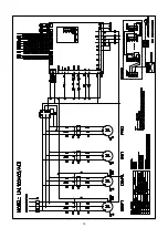
Page 17: ...16 460V 3Ph 60Hz ...

Page 18: ...17 ...

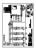
Page 19: ...18 380V 3Ph 60Hz ...

Page 20: ...19 ...

Page 21: ...20 ...

Page 22: ... humidity 90 NOTES 1 THE UNIT IS STRICTLY TESTED BEFORE DELIVERY AND CAN WORK SAFELY IN THE RATED WORKING CONDITIONS 2 FOR THE PERFORMANCE OF THE UNIT IN DIFFERENT WORKING CONDITIONS PLEASE REFER TO PERFORMENC CURVE 3 THIS IS THE NORMAL OPERATING TEMPERATURE RANGE FOR THE UNIT BEYOND THIS TEMPERATURE RANGE THE UNIT CAN ONLY OPERATE FOR A SHORT MOMENT BEFORE A FAILURE ALARM IS TRIGGERED Installatio...

Page 23: ...een units and the wall should be at least 1 0m The hight of the unit 3 0mm high space for ventilate 1m Min 3m AIR DISCHARGE 2 20MM THICKNESS RUBBER SHOCK PAD IS NEEDED BETWEEN THE FOUNDATION AND THE FRAME 3 4M 16 BOLT FIX ONE UNIT 4 N IS THE TOTAL MODULAR UNIT 5 THE NUMBERS IN BRACKETS ARE FOR UAL160A5 Space Allocated for A Single Chilled Water Unit ...

Page 24: ...ed at a proper place to avoid direct hit of strong winds Depending on mounting conditions operation vibration might pass through the groundwork and generate noises in the floor and walls Therefore proper vibration dampening mechanisms such as bumper cushion bumper frame etc should be in place Corners and edges should be properly installed Otherwise the unit might get unbalanced and cause the groun...

Page 25: ... 8 Total hardness mg CaCO3 L 200 Reference items Fe mg Fe L 1 0 S2 mg S2 L 0 NH4 mg NH4 L 1 0 SiO2 mg SiO2 L 50 NOTE REPRESENTS FACTORS THAT MAY CAUSE CORROSION OR SCALING Water System Installation Schematic Diagram Connecting Water Pipes No water pump is provided as an accessory A proper water pump must be installed to overcome resistance of the water pipes Water pressure gauges and thermometers ...

Page 26: ...t be installed at the highest point in the water system A suitable water discharge valve must be installed at the lowest point in the water system The water pipes must be adiabatic to avoid heat loss and condensate water Please follow the Illustration for water system installation and drawings from the design institute while installing the water system Install the Y shaped water filter inside the ...

Page 27: ...is required 1 Shut off the inlet and outlet valves and turn on the bypass valve 2 Run the pump to circulate the water in the system for a while 3 Open up the strainer to inspect the filter 4 Clean the filter if necessary to ensure no debris trap in the piping system 5 Shut off the bypass valve and turn on the inlet and outlet valves 6 System is ready for operation CAUTION If the chiller is operate...

Page 28: ... conditions The pipe system of an air conditioning system must meet the adjustment requirements for partial workload The pipe system of an air conditioning system should use energy saving technologies whenever possible Pipes and accessories of the pipe system must meet the related requirements The design of the pipe system must facilitate maintenance operation and adjustment Determining the diamet...

Page 29: ... IS CALCULATED BASED ON NOMINAL COOLING WATER FLOW AND 5 C ANTI FREEZE IF THE WATER FLOW AND ANTI FREEZE TEMPERATURE CHANGE RELATED VMIN WILL CHANGE 4 THE TABLE IS APPLIED FOR THE WATER VOLUME SELECTION OF NORMAL CHILLER NOT FOR THE CHILLER UNDER LOW LEAVING WATER TEMPERATURE WITH GLYCOL Calculating Volume of Expansion Water Tank An expansion water tank with a proper volume must be installed to ad...

Page 30: ... that multiple units share the same pump the pump lift is calculated according to the circuit that has the maximum resistance usually the unit that is farthest away from the pump NOTE THE WATER FLOW OF THE UNIT SHOULD CALCULATE ACCORDING THE WATER FLOW RANGE Water flow range Model UAL160A5 UAL210A5 Flow range Max value m3 h 208V 230V 3Ph 60Hz 11 87 14 43 460V 3Ph 60Hz 11 87 14 43 380V 3Ph 60Hz 11 ...

Page 31: ...ke sure that the working conditions do not exceed the rated working range Items to be Checked during the Pilot Run Check the following items after the unit has worked properly for a period of time S N Item Checking Method Reference Standard 1 Power supply voltage Voltage Rated voltage 10 2 Working current of a single compressor Current 13 23A 3 Working current of a single fan Current 2 5A 4 Inlet ...

Page 32: ...timely Contaminated water can degrade the cooling capacity and corrode the heat exchanger and water pipes Check whether free air exists in the water pipe system Free air may get into the system even during the air discharging process Discharge air from time to time Clean the Y shaped water filter in the water system periodically Replenishing refrigerant and lubricant Each unit is filled with enoug...

Page 33: ...troller Check parameter settings Check protective device Delay protector Phase order protector High low pressure switch Differential water pressure switch water flow switch Overload protector Protector against extreme temperature of discharged air 3 Plate heat exchanger Check the water quality Clean the plate heat exchanger Seasonal protection measures anti freeze in winter 4 Fin heat exchanger Cl...

Page 34: ...tems of this type use water from taps lakes rivers and wells Although the once through system exchanges heat with the closed water circuit it is not considered as an integral part of the water source heat pump system Once through systems may be troubled by either scale or corrosion This type of water system requires large amount of adjustment water Therefore you need to consider the scale coeffici...

Page 35: ... the pump and the auxiliary heat exchanger NOTE PARTS WITHIN THE DASHED BOX ARE TO BE CONNECTED ONSITE THE OUTPUT VOLTAGE OF THE MODULE INTERFACE IS 220 240 V PARTS WITHIN THE REAL LINE BOX ARE CONNECTED BEFORE DELIVERY A COOLING ONLY UNIT HAS NO 4WV1 AND 4WV2 OUTPUT A SLAVE UNIT HAS NO EXTENSION BOARD UAL E HEAT BPHE ELECTRIC HEATER PUMP WATER PUMP 4WV 4 WAY VALVE FANL FAN AT LOW SPEED FANH FAN A...

Page 36: ...its 5 8 of S1 Slave unit number 5 6 7 8 Slave unit number 5 6 7 8 0 0 0 0 0 8 1 0 0 0 1 0 0 0 1 9 1 0 0 1 2 0 0 1 0 10 1 0 1 0 3 0 0 1 1 11 1 0 1 1 4 0 1 0 0 12 1 1 0 0 5 0 1 0 1 13 1 1 0 1 6 0 1 1 0 14 1 1 1 0 7 0 1 1 1 15 1 1 1 1 DIP address setting 4 8 bits of S2 When the unit is accessed to the BMS system the address of the master unit must be set as below Address number 4 5 6 7 8 Address numb...

Page 37: ... area of at least 0 5mm2 or 20AWG B insulator C Screen layer twisted WTC with a screening factor no less than 95 D Outer jacket PVC NOTE BETTER CHOOSE NETWORK CABLES WITH A TENSER SHIELDING LAYER AND SMALLER TWISTING DISTANCE PLEASE REFER TO THE UL2547 OR UL2791 WIRE SPECIFICATION THE CONTROL WIRE MUST NOT BE LONGER THAN 1000 METERS THE CONTROL WIRE MUST BE AT LEAST 20CM AWAY FROM MAJOR CURRENT WI...

Page 38: ...37 220V 1Ph 60Hz Wired Controller Instruction Dimensions Controller Installation ...

Page 39: ...setting range for inlet water cooling 9 C 25 C 10 C 10 C for units with low water temperature heating 25 C 50 C Temperature setting range for anti freeze 2 C 5 C A LED is used to indicate the status of the unit ON OFF Timed ON OFF a timing schedule can be set for a maximum of 7 days with up to 4 timed actions each day Real time clock Error code display speeds up diagnosis Blue back light will shin...

Page 40: ...unit is turned off When you press PASSWORD the text box at the lower bottom of the LCD displays Input password and 00 Then you can press or to change the number and press OK after getting the correct password the default password set in factory is 55 After you have chosen the correct password the parameters to be set blinks and you can perform the following settings Change operation parameters aft...

Page 41: ... and returns to step You can continue to set other timed actions for a whole week and then quit this setting mode To cancel a timed action set the time for this action to 00 00 To cancel all timed actions press MODE UNIT until you hear a long beeping sound NOTE TIMED ON OFF ACTIONS ARE TRIGGERED WHEN THE TIME OF THE WIRE CONTROLLER REACHES THE SET TIME THEREFORE IF THE TIME OF THE WIRE CONTROLLER ...

Page 42: ...0 64 Fan overload failure of System 2 16 33 discharge temperature 1 is too high 41 65 Too large water inlet and outlet water temperature difference failure 17 34 suction temperature 2 is too high 42 66 Reverse connection of water inlet and outlet water temperature sensors 18 35 discharge temperature 2 is too high 43 67 Failure of water inlet temperature sensor of the master machine 19 36 Low press...

Page 43: ...e following table Code Status Code Status Code Status NULL standby CSP shutdown during cooling HEAT heating REST reset DEF defrosting HSP shutdown during heating COOL cooling TOFs ToFS system with changing water flow rate ToUs ToUS system with constant water fl ow rate ...

Page 44: ...k and troubleshoot the communication lines 2 The LED indicator of the unit displays ERXX and the wired controller displays XX XX represents 00 14 Communication failure of Slave unit No XX 1 Communication line of Slave Unit No XX has broken off Check communication cables and solve the problem 2 The control panel of Slave Unit No XX is not powered on Check and troubleshoot the control panel 3 Incorr...

Page 45: ...n has triggered the overload protector 1 Check whether the electric current parameter of the overload protector is configured correctly by referring to the electric circuit 2 Check whether the resistor of the malfunctioned fan meets specification requirements 6 The LED indicator of the unit displays ER18 and the wired controller displays 18 Pump overload Over current in the pump has triggered the ...

Page 46: ... unit displays ER24 and the wired controller displays 24 High pressure of 2 The motor has broken down cooling Check and troubleshoot Circulatory air is shorted cooling The heat exchanger needs cleaning cooling The fluorine side filter is clogged up Check and replace The water temperature is too high heating Tune down the water temperature The water flow is too small heating Check and troubleshoot ...

Page 47: ...ture of return air in 1 is too high 40 C The slider of the 4 way valve is jammed in the middle Restart the unit and slap slightly on both sides of the 4 way valve If the problem persists replace the 4 way valve The winding of the 4 way valve operates abnormally Replace the winding The temperature of discharge air is too high and has triggered the racing protector of the compressor see Item 17 in t...

Page 48: ...splays 38 Refrigerant leakage in 1 Low pressure sensor failure Replace the low pressure sensor Insufficient refrigerant Add refrigerant 23 The LED indicator of the unit displays ER39 and the wired controller displays 39 Refrigerant leakage in 2 Low pressure sensor failure Replace the low pressure sensor Insufficient refrigerant Add refrigerant 24 The LED indicator of the unit displays ER40 and the...

Page 49: ...e unit displays ER46 TH7 temperature sensor failure TH7 temperature sensor is not properly plugged or has broken off Check the control module and replug the temperature sensor TH7 temperature sensor is shorted open Test whether the resistance of TH7 sensor meets specification requirements replace if not There is something wrong with the test circuit of the temperature sensor in the control module ...

Page 50: ...es of the low pressure sensor is incorrectly connected Reconnect the connecting lines of the low pressure sensor The low pressure sensor is shorted open Repair or replace the lines of the low pressure sensor The Low pressure sensor has broken down Replace the low pressure sensor There is something wrong with the test circuit of the low pressure sensor in the control module Replace the control modu...

Page 51: ...rotector 1 According to the circuit diagram check whether the setting value of current of the corresponding overload protector is correct 2 Check whether the resistance of the corresponding compressor is abnormal 46 The digital pipe of the unit displays ER69 Overload failure of Compressor 2 of System 2 The running current of the compressor is too large Action of overload protector 1 According to t...

Page 52: ...sories can result in water or refrigerant leakage electrical shock fire or explosion Read the User s Manual carefully before using this product The User s Manual provides important safety instructions and warnings Be sure to follow these instructions and warnings If you have any enquiries please contact your local importer distributor and or retailer Warning The air conditioners manufactured by Da...

Reviews: