

Manual #650506b
BIM-17-2
Bus Interface Module for compass and outside temperature
BIM-17-2
S
E
N
D
E
R
S
E
N
D
-
R
E
D
W
IR
E
B
L
A
C
K
W
IR
E
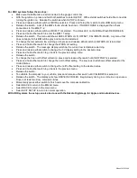
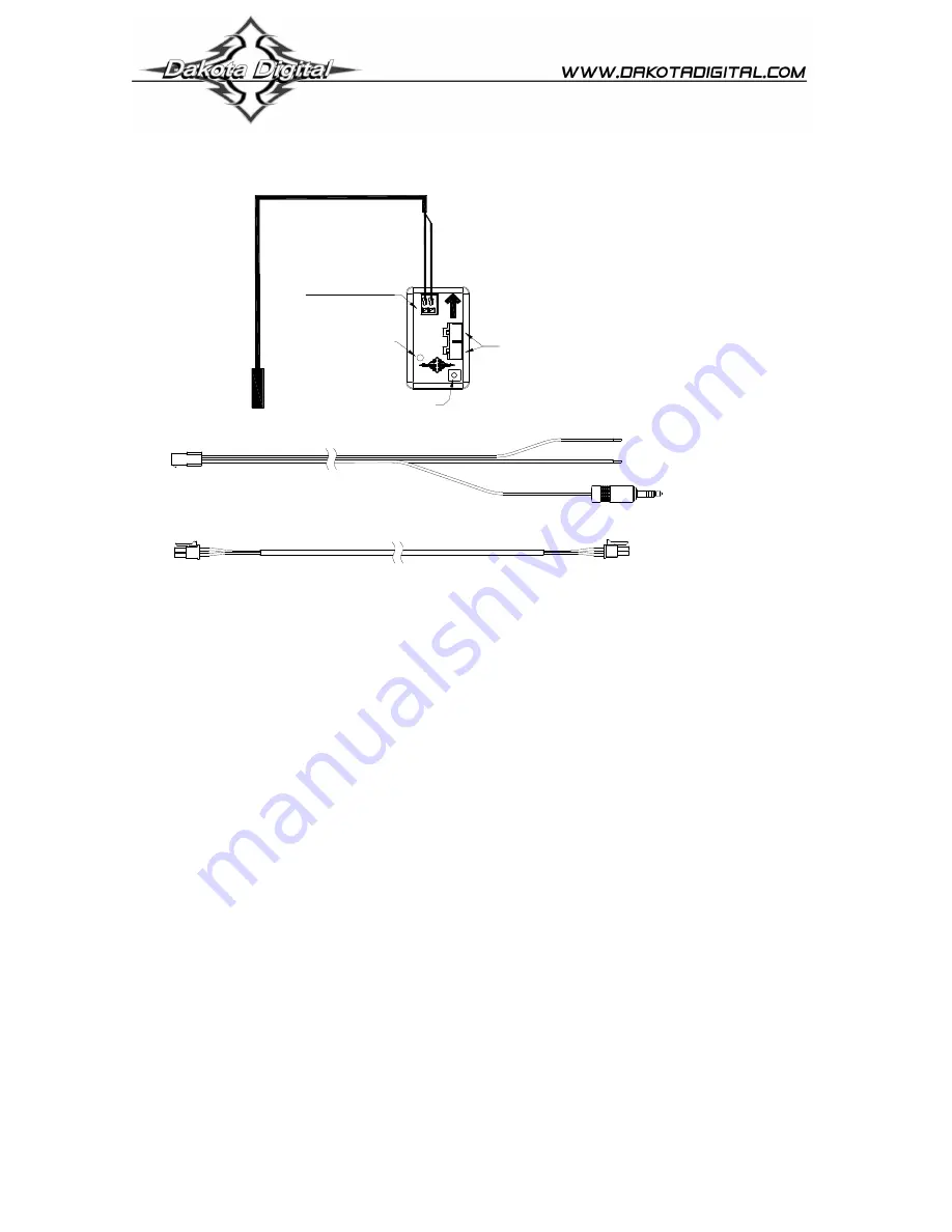
Mount the
temperature sensor in
the front grill area or
another location that
can get good air flow
while the vehicle is
being driven.
setup/status switch
status light
BIM-xx-2
Power & data connectors
+12V
KEY ON POWER
(fused 5 - 20 AMP max)
BIM-xx-2 6 foot power/data harness
BIM-xx-1 adapter harness
Connect to
BIM-xx-2
power/data
harness
if needed
Connect to
BIM-17-2
BLACK WIRE
RED WIRE
Connect to main
chassis ground
To gauge control box
or BIM-xx-1
Connect directly to another BIM-xx-2
or to the BIM-xx-1 adapter harness
The BIM-17-2 must
be mounted solidly so
that it cannot move
and the arrow on the
BIM-17-2 must point
to the front of the
vehicle.
Hold wire release button
when inserting or
removing wires
This Bus Interface Module has an internal compass sensor and an input for the included digital air temperature sensor,
SEN-15-1. There are two interface ports on the module. Either one can be connected to the gauge system or to another
module, allowing several units to be daisy chained together. Do not connect the I/O port to anything other than a Dakota
Digital gauge or BIM. Do not mount the module in the engine compartment; it should be mounted in interior of the vehicle.
If there are several modules being used, it may be easiest to attach this one as the last module in the series. Six foot and
twelve foot cables are included to allow flexibility in the mounting location of the compass module and routing of the cable.
Each unit connected to the bus needs a unique ID number assigned to it. The unit comes preset with an ID value that
should not conflict with any other BIM connected to your system. If needed the ID can be automatically reset to an
unused value. The compass must be calibrated in the vehicle before it can begin reading properly. The status light
will flash between red and green until it has been calibrated in your vehicle.
Air temperature sensor mounting:
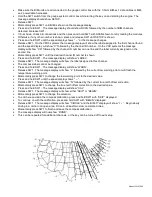
Make sure the temperature sensor probe can get adequate air flow. For outside temperature measurement, the
front grill area or above the front bumper may be a good location. It should be in a location that can get good air flow
across it while the vehicle is moving. When you are sitting still for a long period of time after driving the temperature
reading may begin to rise due to the engine heat radiating forward.
Compass module mounting:
Do not mount the module in the engine compartment; it should be mounted in interior of the vehicle. Avoid any
strong magnets such as fan motors and speakers, high current wiring such as alternator or fan wires, or steel bars. Sheet
steel is much better than steel bars or brackets since the bars and brackets can bend the magnetic fields causing
compass errors. Some roads have steel bars in them for reinforcement which can cause interference. Mounting the
module higher in the vehicle helps eliminate this. Magnetic interference drops off very rapidly with distance, so even small
movements away from the interference can help significantly.
The BIM unit should be solidly so that it cannot move or shift. The arrow on the BIM should point directly to the
front of the vehicle. Any error in the mounting direction will cause an error in the compass heading. If the BIM moves or
shifts then the calibration will no longer be correct and the readings will be wrong.
The calibration and warning points are set up through the gauge display system. The calibration should be done
in an open area such as an empty parking lot to avoid any external interference.
Only VFD3/3X controls with a plastic case support adding BIM’s.
For VFD3, VFD3X, and VHX systems follow these steps:


