DD2546969 Rev 0
13 May 2013
PO Box 5128 201 Daktronics Drive, Brookings, SD 57006-5128
tel: 800-325-8766 fax: 605-697-4700
www.daktronics.com
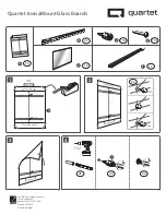
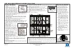
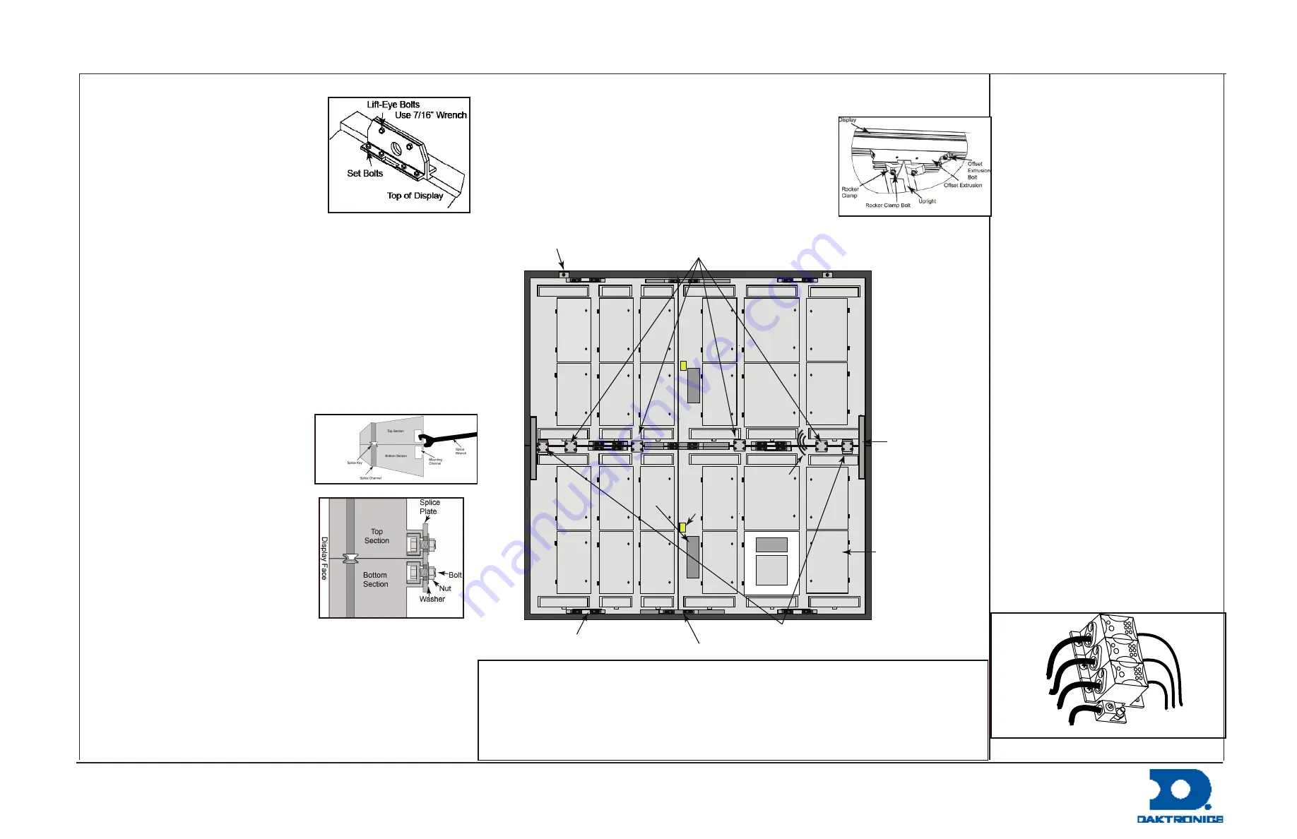
1.
Verify lift-eye and set bolts are
secure.
2.
Identify the display sections.
3.
If there is a horizontal splice required
(side by side), install a C-shaped
splice plate at the top and bottom
of one of the display sections so it
can catch and engage the second
section. Note: There are examples of
installation hardware installation locations on the back of
this quick guide. The hardware installation location can also
be located on the shop drawing.
4.
Lift a display section.
5.
Carefully guide and pull the two display sections together.
6.
Install the required nuts and bolts to secure the two display
sections together.
7.
Ensure the LEDs align between the two display sections.
8.
Repeat
Steps 3 - 7
for all horizontal splices.
9.
Attach the crane to the lift-eyes in the top section.
10.
Remove the bolts that hold the lift-eyes in the bottom section
together and to the display. Slide the two pieces of the lift-
eye past each other and lift them out of the channel.
11.
Lift the top section.
12.
Lower the top section on to the
bottom section.
13.
Use the splice wrench to align the
display sections.
14.
Verify the LEDs on both display
sections align with each other.
15.
Install and evenly distribute the flat
splice plates along the back of the
display.
16.
Install the C-shaped splice plates at
each end of the display.
17.
Install the vertical splice tubes so
they are split evenly between the
top and bottom display sections.
18.
Measure the uprights on the
structure head and install the
mounting clamps on the back of the display to match the
spacing.
19.
If needed, relocate the DMP and the ISP enclosure to the
alternate location to avoid structural interference when
installed.
20.
Install the display borders.
21.
Connect the signal splice cables between the display sections
(A to A, and B to B).
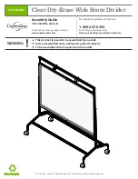
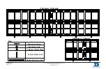
1.
Refer to the display riser
diagram for required power.
2.
Run conduit from the main
distribution panel to the
display power entrance(s).
3.
Loosen the six screws that
secure the power entrance
cover and remove the cover.
4.
Feed the power cable through
the conduit into the power
entrance.
5.
Connect the green ground
wire to the ground lug at the
bottom of the power entrance
box and tighten to 45 in-lbs.
6.
Connect power line 1 to Line
1 on the tap and tighten to 57
in-lbs.
7.
Connect power line 2 to Line
2 on the tap and tighten to 57
in-lbs.
8.
Connect the neutral line to the
neutral tap and tighten to 57
in-lbs.
9.
Verify the breakers for the
control equipment and surge
suppressor are on.
10.
Verify the breaker for the
Backlit ID is off unless there is
a backlit ID.
11.
Replace and secure the power
entrance cover.
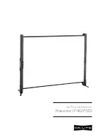
Display Installation
Electrical Installation
Line 1
Line 2
Neutral
Ground
To Display
4203 Series Digital Billboard Installation Quick Guide
Note
•
There are no display filters on the 4203 series. Filter retrofit kits are available for displays in
highly corrosive environments. Work with the Account Service Manager if a filter retrofit kit is
needed.
•
If your display has an external control enclosure, refer to the quick guide shipped with the
enclosure for external enclosure installation.
•
For full installation instructions, refer to the installation manual located in the spare-parts box.
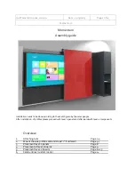
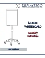
22.
Install the webcam and webcam arm.
23.
Connect the webcam Ethernet cable to the back of the display (below the power
entrance box) and connect the green grounding cable to the back of the display.
24.
Lift the display to the structure.
25.
Lower the display until it rests on all the display
ledger brackets. If needed, insert metal shims until the
display is resting on all ledger brackets.
26.
Connect and secure all mounting clamps to the
uprights.
Note:
Tighten all mounting hardware to 75
ft-lb.
27.
Remove the crane support.
Flat Splice Plates
“C” Splice Plates
Vertical
Splice
Tubes
Power Entrance
Splice Cables
Lift-Eye
Mounting Clamp
Horizontal Splice Tubes
DMP
ISP
Alternate
DMP and
ISP Bay
Surge