background image


Remote Control System 

RC-100 

DataMaster Operation Manual 


ED-15576


Rev 4 

– 3 May 2016


201 Daktronics Drive  PO Box 5128  Brookings, SD 57006-5128 
Tel: 1-800-DAKTRONICS (1-800-325-8766)  Fax: 605-697-4700 
www.daktronics.com/support 


Summary of Contents for RC-100

Page 1: ...trol System RC 100 DataMaster Operation Manual ED 15576 Rev 4 3 May 2016 201 Daktronics Drive PO Box 5128 Brookings SD 57006 5128 Tel 1 800 DAKTRONICS 1 800 325 8766 Fax 605 697 4700 www daktronics co...

Page 2: ......

Page 3: ...missions No part of this book covered by the copyrights hereon may be reproduced or copied in any form or by any means graphic electronic or mechanical including photocopying taping or information sto...

Page 4: ......

Page 5: ...4 Server Client Mode Setting 10 3 5 Wireless Base Station LEDs 11 LED Error Diagnostics 12 Section 4 RC 100 Handheld Controller 13 4 1 Powering the Controller On and Off 13 Using the Keypad 13 Using...

Page 6: ...er Operation 27 6 2 International Gas Price Display Operation 27 Section 7 Rate Display Operation 29 7 1 Rate Display Controller Operation 29 Section 8 Lottery Display Operation 31 8 1 Lottery Display...

Page 7: ...touch hot surfaces or hang over the edge of a table that would damage or cut the cord If an extension cord is necessary a three pronged polarized cord should be used Arrange the cord with care so that...

Page 8: ...onics Customer ID Number ________________________________________________ To participate in the Exchange Program follow these steps 1 Call Daktronics Customer Service 866 343 3122 2 When the new excha...

Page 9: ...ent damage during shipment Electronic components such as printed circuit boards should be placed in an antistatic bag before boxing 4 Enclose name address phone number the RMA number a clear descripti...

Page 10: ......

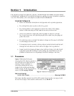
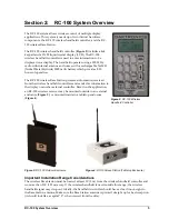
Page 11: ...ion received from the wireless handheld controllers and sends this information to the display or another external controller Based on the application an RC 100 wireless receiver may be mounted outside...

Page 12: ......

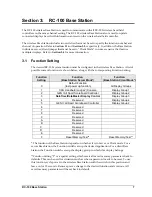
Page 13: ...ion Base Station Client Mode 0 Default Function last power up function All Display Groups 1 CAN Handheld Judges Console Display Group 1 2 GEN I All Sport Scoreboard Controller Display Group 2 3 DataTi...

Page 14: ...witch The function setting may also be set in hardware via the loading of jumpers W1 W4 to select the correct setting value In this case switch S2 may not be loaded on the PCB DataTime DataMaster Disp...

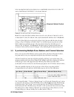
Page 15: ...wireless system uses frequency hopping technology to maximize range and minimize interference from other systems When multiple server Base Stations are installed within range of each other approximat...

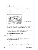
Page 16: ...l number to avoid interference within the channels 3 4 Server Client Mode Setting The RC 100 wireless Base Station can operate in either Server Mode or Client Mode depending on application requirement...

Page 17: ...the wireless Base Station in Client Mode For Server Mode leave the jumper over the bottom two posts factory default 3 5 Wireless Base Station LEDs The wireless Base Station circuit board includes seve...

Page 18: ...ithin range If one is found this LED flashes continuously to indicate that only one server Base Station is allowed on a given channel Once in operation mode this LED will either be on or off to indica...

Page 19: ...p the handheld controller powered on 4 2 Battery Operation When the controller is powered on an indicator on the top line of the LCD shows the current battery status Figure 10 The three segments withi...

Page 20: ...time by pressing and holding the CONFIG key for 5 seconds Use the and arrow keys to move through the possible configuration items Setting Default Radio Channel Number Display Action Press ENTER to se...

Page 21: ...n determines the operation of the handheld and all operation is specific to the wireless Base Station Function selected Switching to Connect Mode After all initialization and configuration is complete...

Page 22: ...ion 2 4 5 Common Keys Several keys on the default keypad layout are common to multiple wireless handheld applications These keys are noted in Figure 14 For a description of the function of keys for a...

Page 23: ...ing another key to activate a secondary function Refer to the section following this table for more information 5 CONFIG ENTER YES EDIT The CONFIG operation of this key is described in Section 4 4 The...

Page 24: ......

Page 25: ...down arrow keys to select the desired application from GAS PRICE RATE DISPLAY or LOTTERY Press ENTER to accept Note Once the application has been set the wireless Base Station will continue to use it...

Page 26: ...isplay can detect the level of ambient light at the display location and dim the sign s LEDs accordingly This function is known as automatic dimming When the manual dimming function is selected the LE...

Page 27: ...ss ENTER to accept this intensity Manual If MANUAL dimming is selected the following will be shown on the LCD Display Action NN Current intensity 1 16 Max intensity 16 Press the up or down arrow keys...

Page 28: ...current cent value Press the up or down arrow keys to move to the previous or next item in the list Press ENTER to edit the item shown on the LCD Press the MENU key a second time or press the CLEAR k...

Page 29: ...to set the display option or press CLEAR to exit the menu The current configuration is shown on the bottom line of the LCD Press the down arrow key to select one of the following values 00 00 default...

Page 30: ...appear asking to confirm the selection Press ENTER again to update the display option Display Status Select DISPLAY STATUS to view information about the display Display Action Press ENTER to get the d...

Page 31: ...de The next time the RC 100 is powered on the passcode must be entered before it will operate The passcode is also required when switching display functions If an incorrect passcode is entered the err...

Page 32: ...n Press ENTER to set the time of day or press CLEAR to exit the menu Use the number pad to edit the time Press the down arrow key to set AM or PM Press ENTER when finished MM current month value DD cu...

Page 33: ...Press ENTER to modify any of the line settings L current line D current dollar value CC current cent value Use the number pad to edit the price value for the line Press ENTER to accept the new value o...

Page 34: ...ss MENU 2 Use the arrow keys to select DISPLAY OPTION and then press ENTER 3 Use the down arrow to move the decimal point to the desired position 4 Press ENTER twice The display should now show the de...

Page 35: ...r entering the Rate Display mode the LCD will toggle between the two screens shown at left Press the up or down arrow keys to scroll through the current setting for any of the lines on the display Pre...

Page 36: ......

Page 37: ...play Action After entering the Lottery Display mode the LCD will toggle between the two screens shown at left Press the up or down arrow keys to scroll through the current setting for any of the lines...

Page 38: ......

Page 39: ...he handheld is within minimum and maximum range limits refer to Section 2 Cycle power to the wireless Base Station and retry the connection Make sure that there are no other wireless Base Stations wit...

Page 40: ...failure type The LEDs will flash on for a long period of time followed by a series of short flashes that give the error type This sequence will repeat 5 times after which the Base Station will reset I...

Page 41: ...on number After verifying the correct numbers follow the steps below to replace the battery 1 Remove the two Philips screws one on the top and one on the bottom to separate the bottom half of the case...

Page 42: ......

Page 43: ...ndix A Reference Drawings Drawing Title Drawing Number Insert LL 2617 RC 100 Price Displays A 244374 System Riser Diagram DataMaster RC 100 A 244838 Base Station Inside Installation A 245626 Dipswitch...

Page 44: ......

Page 45: ......

Page 46: ...ANS WITHOUT THE EXPRESSED WRITTEN CONSENT OF DAKTRONICS INC COPYRIGHT 2012 DAKTRONICS INC DAKTRONICS INC AV DRAWN DATE SHEET JOB NO REV DATAMASTER LED DISPLAYS SYSTEM RISER DIAGRAM DATAMASTER RC 100 K...

Page 47: ......

Page 48: ......

Page 49: ...Daktronics Warranty and Limitation of Liability 39 Appendix B Daktronics Warranty and Limitation of Liability...

Page 50: ......

Page 51: ...placement parts or Equipment will be new or serviceably used comparable in function and performance to the original part or Equipment and warranted for the remainder of the Warranty Period Purchasing...

Page 52: ...ectors employees or agents be liable for any claims asserting or based on a loss of use of the facility or equipment lost business revenues or profits loss of goodwill failure or increased cost of ope...

Reviews: