background image

Evaluates:  MAXQ3210

MAXQ3210 Evaluation Kit

______________________________________________

Maxim Integrated Products

1

For pricing, delivery, and ordering information, please contact Maxim/Dallas Direct! at 
1-888-629-4642, or visit Maxim’s website at www.maxim-ic.com.

Rev 0; 6/06

General Description

The MAXQ3210 evaluation kit (EV kit) is a proven plat-
form to conveniently evaluate the capabilities of the
MAXQ3210 voltage regulator microcontroller. The kit
contains the MAXQ3210 with pins brought out to head-
ers, JTAG programming interface, 9V battery clip,
piezoelectric horn, and pushbuttons and LEDs to con-
trol and display board operation. With the included
power supply, software, serial-to-JTAG interface board,
and an RS-232 cable connected to a personal comput-
er, the kit provides a completely functional system ideal
for evaluating the capabilities of the MAXQ3210.

MAXQ3210 EV Kit Board with Processor and
3.57MHz Crystal Installed

Serial-to-JTAG Interface Board and JTAG Cable

MAXQ3210 Evaluation Kit CD-ROM

Features

Easily Loads Code Using Bootstrap Loader and
Serial-to-JTAG Interface Board

JTAG Interface Provides In-Application
Debugging Features

Step-by-Step Execution Tracing
Breakpointing by Code Address, Data Memory

Address, or Register Access

Data Memory View and Edit

9V Battery Clip for Use with MAXQ3210 Voltage
Regulator

Piezoelectric Horn with Optional Volume
Adjustment Jumpers

Evaluation Kit Board can be Powered Directly
Over JTAG Interface

Processor Clock can be run from Crystal or RC
Oscillator Circuit

Direct LED Drive from Port Pin P0.7

32-Step Digital Potentiometer for Experimenting
with On-Board Comparator

Pushbutton Switches for Reset and Interrupt
Generation

Prototyping Area Inc5V Rail and Ground

Test/Expansion Header Includes All Device GPIO
and Piezoelectric Driver Pins

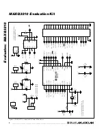
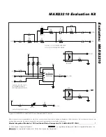
Board Schematics Included to Provide a
Convenient Reference Design

Evaluation Kit Contents

Ordering Information

PART

DESCRIPTION

MAXQ3210-KIT

Evaluation Kit for MAXQ3210
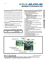
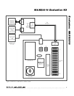
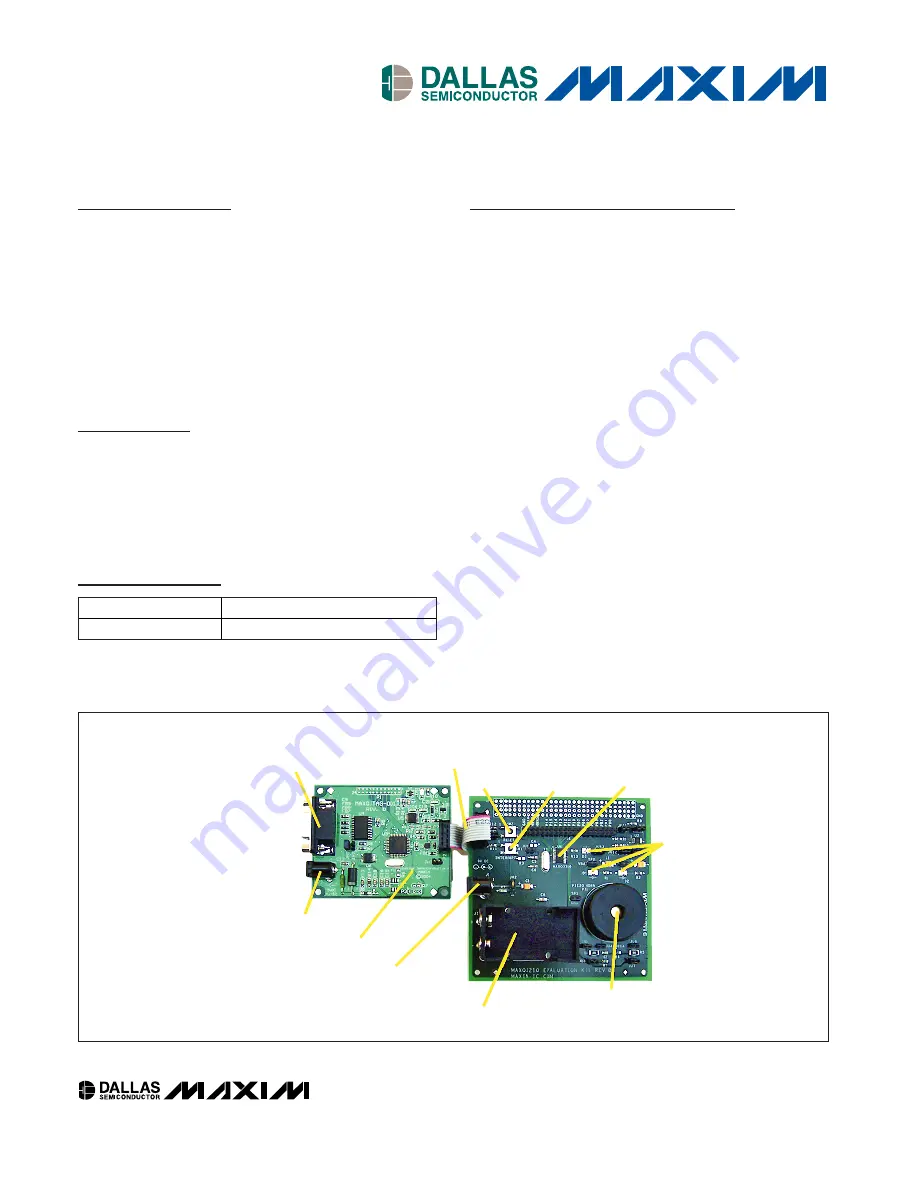
SERIAL DEBUG PORT

JTAG INTERFACE

CABLE

RESET

INTERRUPT

SWITCH

MAXQ3210

LEDs

PIEZO HORN

9V BATTERY CONNECTOR

9V POWER CONNECTOR

JTAG INTERFACE BOARD

5V POWER CONNECTOR

Figure 1. MAXQ3210 Evaluation Kit Setup

MAXQ is a registered trademark of Maxim Integrated Products, Inc.

Summary of Contents for Maxim MAXQ3210

Page 1: ...oads Code Using Bootstrap Loader and Serial to JTAG Interface Board JTAG Interface Provides In Application Debugging Features Step by Step Execution Tracing Breakpointing by Code Address Data Memory Address or Register Access Data Memory View and Edit 9V Battery Clip for Use with MAXQ3210 Voltage Regulator Piezoelectric Horn with Optional Volume Adjustment Jumpers Evaluation Kit Board can be Power...

Page 2: ...JU1 JU3 JU13 12 2 pin NO 1 x 2 0 1 jumpers 3M 929834 02 02 JU2 1 3 pin NO 1 x 3 0 1 2 of 3 jumper 3M 929834 02 03 J1 1 9V battery clip Keystone 1294 J2 1 DC power jack 2mm CUI Inc PJ 002A J3 1 2 x 5 0 100 spaced header 3M 929836 02 05 J4 1 2 x 20 0 100 spaced header 3M 929836 02 20 DESIGNATION QTY DESCRIPTION SUPPLIER PART NUMBER PT1 1 Piezoelectric horn high volume CUI Inc CEP 1172 R1 1 1 2kΩ 1 8...

Page 3: ...oards from a Single Power Supply If the serial to JTAG interface board is being used a single power supply can be used to power both boards as follows Connect a 5V 5 regulated DC wall supply cen ter post positive to the J2 power plug of the serial to JTAG interface board Connect the JH3 jumper on the serial to JTAG inter face board Connect the JU1 jumper on the MAXQ3210 EV kit board Connect a jump...

Page 4: ... RC bit to 0 upon startup you can reload the normal serial to JTAG board firmware to go back to normal tools operation MAXQ3210 Evaluation Kit 4 _____________________________________________________________________ JUMPER SETTING EFFECT JU1 No jumper REGOUT is not connected to JTAG 5V Drive from internal regulator or bench supply JU1 Pins 1 and 2 connected REGOUT is connected to the 5V supply from...

Page 5: ...PPLY 5V DC 5 300mA USER SUPPLIED POWER SUPPLY 6V 9V DC 300mA USER SUPPLIED WHEN NOT USING JTAG BOARD RS 232 J1 SERIAL JTAG CONNECTOR SERIAL TO JTAG INTERFACE BOARD JTAG INTERFACE JTAG CONNECTOR J2 P2 J2 SW1 SW2 J4 DEVICE HEADER PINS INTERRUPT RESET CRYSTAL 9V BATTERY CLIP PIEZO BUZZER J3 5V GND PROTOTYPE AREA MAXQ3210 Figure 3 MAXQ3210 Evaluation Kit Functional Layout ...

Page 6: ...P0 4_VREF 3 P0 3_CMPO 4 P0 2_T2P 5 P0 1_T2PB 6 P0 0 7 P1 6 8 P1 5 9 P1 4_TDO 10 11 12 23 24 22 21 20 19 18 17 16 15 14 13 3 1 5 7 9 11 13 15 17 19 21 23 25 27 29 31 33 35 37 39 4 2 6 8 10 12 14 16 18 20 22 24 26 28 30 32 34 36 38 40 P1 3_TCK P0 0 P0 1_T2PB P0 2_T2P P0 3_CMPO P0 4_VREF P0 5_CMPI P0 6_INT P0 7_LED P1 0_TDI P1 1_RESET P1 2_TMS P1 3_TCK P1 4_TDO P1 5 P1 6 HORNS HORNB FEED P0 4_VREF GN...

Page 7: ...Semiconductor Corporation INTERRUPT SW1 JU4 P0 6_INT HORNS FEED 3 4 2 VCC5 P 05_CMPI VCC5 JU9 JU11 JU10 JU12 1 1 2 2 2 1 P0 0 P1 5 P1 6 CLOSE JU9 JU10 JU11 JU12 TO SET COMPARATOR INPUT TO ADJUSTABLE DIGITAL POT VALUE CLOSE JU5 JU7 JU8 TO ENABLE PIEZO HORN CLOSE JU4 JU6 TO ENABLE LOUD VOLUME CLOSE JU13 TO DRIVE LED WITH P0 7 1 1 2 JU7 R5 1kΩ 1 2W R6 68kΩ R14 30kΩ C9 2nF CEP 1172 PT1 1 2 1 2 JU6 1 H...

Page 8: ...Mouser Electronics Authorized Distributor Click to View Pricing Inventory Delivery Lifecycle Information Maxim Integrated MAXQ3210 KIT ...

Reviews: