
PART#: 212-2014-K
1
July 30th, 2019
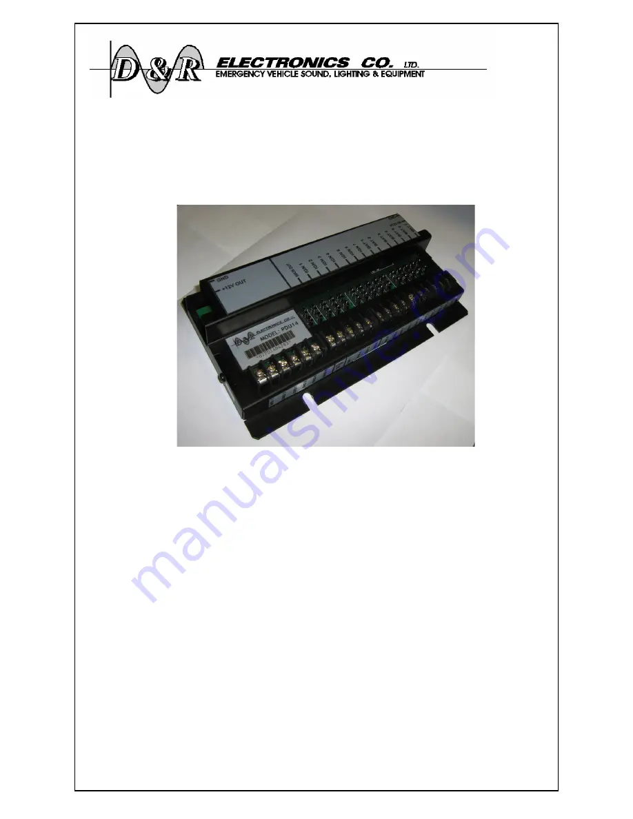
Power Distribution Unit
PDU14-K
Installation/Operations Manual
Table of Contents
Applicable Models ............................................ 2
Introduction ....................................................... 2
General Warnings .............................................. 2
Unpacking &Pre-Installation Check ................. 3
Installation & Mounting ................................... 3
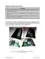
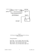
Wiring and Setup Instructions ........................... 4
Maintenance ...................................................... 8
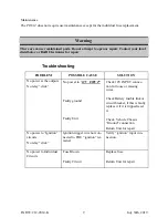
Troubleshooting ................................................ 8
Parts List ......................................................... 10
Product Specifications .................................... 11
Warranty .......................................................... 12
PDU14


