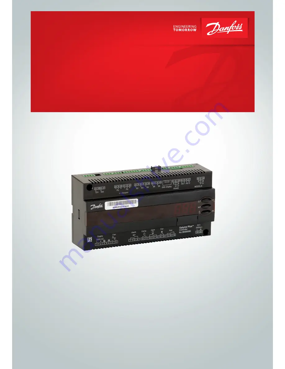
background image

Controller for Condensing unit


Optyma Plus 

TM


User Guide

Summary of Contents for Optyma Plus

Page 1: ...Controller for Condensing unit Optyma Plus TM User Guide...

Page 2: ...value The controller can also control the heating element in the crank case so that oil is kept separate from the refrigerant For excess discharge temperature the liquid injection will be acti vated i...

Page 3: ...terminal 15 16 will be active when the fan is in operation In menu F17 the user can define which of the two controls to use Jog Min Jog low Jog Speed Speed Required capacity Fan speed at start When th...

Page 4: ...set delay time the compressor will be stopped The compressor will only be re started once the temperature is 10 K lower than the set value The above mentioned re start restrictions must also be compl...

Page 5: ...in the master gateway system man ager Heating element in the crankcase The controller has a thermostat function which can control the heating element for the crankcase Oil can thus be kept separate fr...

Page 6: ...d for the suction pressure Ts in degrees r23 Ts Ref Reference Tc Here the current controller reference for condensing pressure Tc can be read out in degrees r29 Tc Ref Minimum condensing temperature l...

Page 7: ...the temperature is still too high An alarm will also be issued c72 Disch Del Max pressure Max condensing pressure The maximum permitted condensing pressure is set here If the pressure increases the co...

Page 8: ...an be limited here The value can be entered by setting the nominal speed of 100 to the desired percentage F19 MaxFanSpeed Manual fan speed control An override of the fan speed control can be performed...

Page 9: ...type of condensing unit Factory set After the first setting the value is locked and can only be changed once the control ler has been reset to its factory setting When entering the refrigerant settin...

Page 10: ...e The time the compressor must operate at Boost speed P80 ORM BoostTim Service Service Read pressure Pc u01 Pc bar Read temperature Taux u03 T_aux Status on DI1 input On 1 closed u10 DI1 status Status...

Page 11: ...us codes have the following meanings Ctrl state Normal regulation S0 0 When the compressor is operating it must run for at least x minutes S2 2 When the compressor is stopped it must remain stopped fo...

Page 12: ...Set o30 A16 DI2 alarm DI2 alarm Check the function that sends a signal at the DI2 input A17 HP Alarm C73 DI3 Alarm High low pressure alarm See instructions for the condensing unit A45 Standby mode Sta...

Page 13: ...eady be set to 0 which means stopped regulation 2 Select refrigerant via parameter o30 3 Open parameter r12 and start the regulation Start stop at input DI1 or DI2 must also be activated 4 Go through...

Page 14: ...ion c83 30 s 360 s 60 s Liquid Injection Offset c88 0 1 K 20 0 K 5 0 K Liquid Injection hysterese c89 10 0 K 30 0 K 15 0 K Compressor stop delay after Liquid injection c90 0 s 10 s 3 s Desired compres...

Page 15: ...h Read out of compressor operating time Value must be multiplied by 1 000 The value can be adjusted P49 0 h Read out of operating time of heating element in crankcase Value must be multiplied by 1 00...

Page 16: ...ust then be carried out by one of the other methods Supply voltage 230 V a c This must be the same phase for all 230 V connections FAN Fan connection Speed controlled internally Alarm There is a conne...

Page 17: ...Min 28 V a c Max 2 0 A Leak 1 mA Relays CE 250 V a c Comp CCH 4 3 A Alarm Fan Aux 4 3 A Analog output 2 pcs 0 10 V d c For external speed control of fans and compressors Min load 10 K ohm Max 1 mA Env...

Page 18: ...s logotype are trademarks of Danfoss A S All rights reserved Ordering Type Function Code no Optyma PlusTM Condensing unit controller Prepared for data communication Plug for screw terminals not enclos...

Reviews: