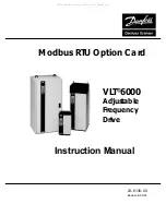
background image

                     VLT

®

 5000

Rev. 2003-09-01

www.danfoss.com/drives

175R0504

MG10P222

*MG10P222*

XREF__BC

NOT LOADED ON RIP

Instruction Manual

Modbus RTU

                     VLT

®

 6000 HVAC

All manuals and user guides at all-guides.com

all-guides.com

Summary of Contents for VLT 5000

Page 1: ...VLT 5000 Instruction Manual Modbus RTU VLT 6000 HVAC All manuals and user guides at all guides com a l l g u i d e s c o m...

Page 2: ...23 6130 00 Revision B 02 03 Modbus RTU Option Card VLT 6000 Adjustable Frequency Drive Instruction Manual All manuals and user guides at all guides com...

Page 3: ...t is properly grounded Wear safety glasses whenever working on electric control or rotating equipment WARNING Warnings Against Unintended Start 1 While the drive is connected to the AC line the motor...

Page 4: ...ation of Modbus Option Card Modbus RTU Option Card Environmental Requirements 9 Power Supply 9 Installation 9 Status LEDs 13 Option Card Operability Loop Back Test 13 Network Configuration Remote Term...

Page 5: ...ler that supports the interfaces defined in this document It is assumed that you have full knowledge of the capabilities and limitations of the controller This manual assumes that you have a controlle...

Page 6: ...queries from the master The Modbus RTU protocol establishes the format for the master s query by placing into it the device or broadcast address a function code defining the requested action any data...

Page 7: ...rd 6 Pin Connector to VLT 6000 Terminals Mounting Hole LEDs Baud Rate and Parity 9 Input DIP Switch 3 Pin EIA 485 Connector Mounting Hole Address and Termination 9 Input DIP Switch pin 1 pin 1 pin 9 t...

Page 8: ...s Set input switches 1 3 to ON to select 9600 baud rate Set input switches 4 and 5 to ON to select no parity 9600 Baud Rate and No Parity Switch Settings Switches 6 9 are unassigned reserved switches...

Page 9: ...he VLT 6000 Operating Instructions for details on selecting and changing parameter values if necessary VLT 6000 Parameter Settings Parameter 500 Protocol FC protocol Parameter 501 Address 001 Paramete...

Page 10: ...lectronic components of adjustable frequency drive and Modbus RTU option card are sensitive to electrostatic discharge ESD ESD can reduce performance or destroy sensitive electronic components Follow...

Page 11: ...nect Local Control Panel LCP cable Remove control wiring by unplugging connector terminals A Remove grounding clamps B by removing two screws holding each in place Save screws for reassembly Loosen tw...

Page 12: ...VLT 6000 terminal 69 Wire Modbus interface connector com pin 3 to VLT 6000 terminals 39 and 61 Wire Modbus interface connector RTxD pin 4 to VLT 6000 terminal 68 Plug Modbus interface connector into...

Page 13: ...card cassette by alternately tightening two captive screws A Tighten to 8 in lbs Route control wires through clamp fasteners B and secure clamps with two screws Connect control terminals C by firmly p...

Page 14: ...rewire the option card connectors Ensure that power has been removed from adjustable fre quency drive for a minimum of 14 minutes to allow voltage to dissipate Remove the option card in accordance wit...

Page 15: ...otocol No response is needed on broadcast messages To ensure the attribute data returned is the most current each attribute access must include one attribute only A typical message frame is shown belo...

Page 16: ...to slave device contains additional information which the slave must use to take the action defined by the function code This can include items like discrete and register addresses the quantity of it...

Page 17: ...value The parameter value block consists of 2 words 4 bytes The value depends on the command given AK PWE is zero filled on reads On writes PWE is filled with the data field of the Modbus write messag...

Page 18: ...a text string Conversion The different attributes for each parameter can be seen in the section on factory settings Since a parameter value can only be transferred as a whole number a conversion facto...

Page 19: ...t 03280 Parameter 328 Pulse Feedback Max Freq 03290 03999 Reserved 04000 Parameter 400 Reset Function 04270 Parameter 427 PID Lowpass Filter Time 04280 04999 Reserved 05000 Parameter 500 Protocol 0566...

Page 20: ...RTU option car TU option car TU option car TU option car TU option card d d d d Modbus function 0FHEX Force Multiple Coils Message sent to Modbus R Message sent to Modbus R Message sent to Modbus R Me...

Page 21: ...Message sent to Modbus R Message sent to Modbus R Message sent to Modbus R Message sent to Modbus R Message sent to Modbus RTU option car TU option car TU option car TU option car TU option card fr d...

Page 22: ...from Modbus R om Modbus R om Modbus R om Modbus R om Modbus RTU option car TU option car TU option car TU option car TU option card d d d d Byte 0 Byte 1 Byte 2 Byte 3 Byte 4 Byte 5 Byte 6 Slave Addre...

Page 23: ...R Message sent to Modbus R Message sent to Modbus R Message sent to Modbus RTU option car TU option car TU option car TU option car TU option card fr d fr d fr d fr d from Modbus master om Modbus mas...

Page 24: ...tion The tables below identify the codes and describe their meaning Modbus Code decimal Meaning 00 The parameter number does not exist 01 There is no write access to the parameter 02 The data value ex...

Page 25: ...arting Address LO 00 No of Points HI 00 No of Points LO 10 Error Check CRC Response The coil status in the response message is packed as one coil per bit of the data field Status is indicated as 1 ON...

Page 26: ...00HEX OFF or FF 00HEX ON Example of a request to set coil 1 addressed as 0 from slave device 01 Field Name Example HEX Slave Address 01 Function 05 Coil Address HI 00 Coil Address LO 00 Force Data HI...

Page 27: ...oils starting at coil 1 addressed as 0 from slave device 01 Field Name Example HEX Slave Address 01 Function 0F Coil Address HI 00 Coil Address LO 00 Quantity of Coils HI 00 Quantity of Coils LO 0A By...

Page 28: ...ve Address 01 Function 03 Starting Address HI 00 Starting Address LO 00 No of Points HI 00 No of Points LO 03 Error Check CRC Response The register data in the response message are packed as two bytes...

Page 29: ...1 is addressed as 0 Example of a request to preset register 40002 to 00 03HEX in slave device 01 Field Name Example HEX Slave Address 01 Function 06 Register Address HI 00 Register Address LO 01 Prese...

Page 30: ...X and 01 02HEX in slave device 1 Field Name Example HEX Slave Address 01 Function 10 Starting Address HI 00 Starting Address LO 01 No of Registers HI 00 No of Registers LO 02 Byte Count 04 Write Data...

Page 31: ...All manuals and user guides at all guides com a l l g u i d e s c o m...

Page 32: ...Inc 8800 West Bradley Road P O Box 245041 Milwaukee Wisconsin 53224 9541 Phone 414 355 8800 Fax 414 355 6117 Toll free 800 621 8806 E mail graham grahamdrives com http www namc danfoss com All manuals...

Page 33: ...All manuals and user guides at all guides com...

Reviews: