
FALCON 7X
02-24-05
CODDE 1
PAGE 1
/ 6
DGT97831
ATA 24 – ELECTRICAL POWER
GENERAL
ISSUE 2
DASSAULT AVIATION Proprietary Data
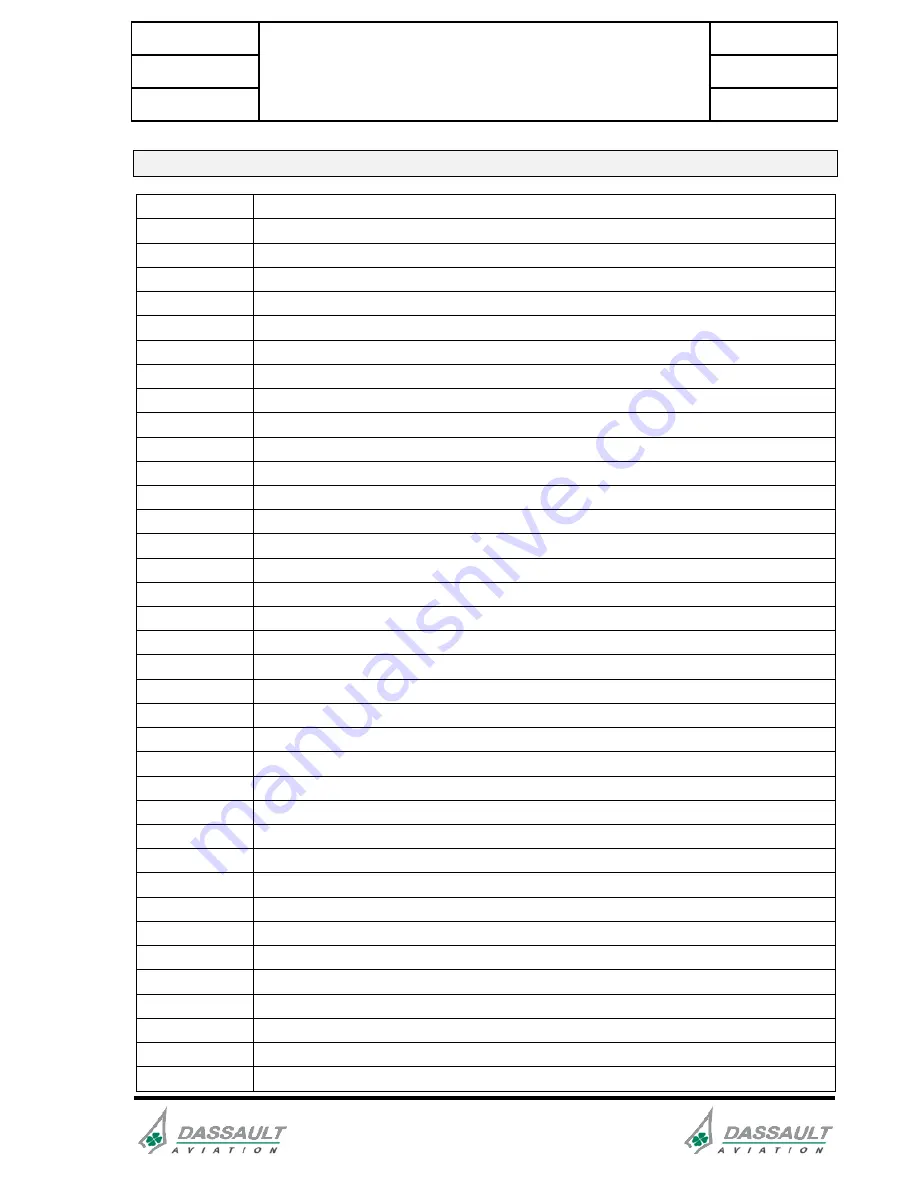
ACRONYMS
AC
Alternative Current
APU
Auxiliary Power Unit
BC
Battery Contactor
BIT
Built In Test
BTC
Bus Tie Contactor
CAS
Crew Alerting System
CB
Circuit Breaker
CLSC
Cabin Load Shed Contactor
CMC
Central Maintenance Computer
DC
Direct Current
ECU
Electronic Control Unit
EEC
Engine Electronic Controller
FADEC
Full Authority Digital Electronic Control
FBW
Fly By Wire
GCU
Generator Control Unit
GLC
Generator Line Contactor
GLSC
Galley Load Shed Contactor
GPC
Ground Power Contactor
GPU
Ground Power Unit
GSB
Ground Service Bus
LFSPDB
Left Front Secondary Power Distribution Box
LH
Left Hand
LPPDB
Left Primary Power Distribution Box
LRSPDB
Left Rear Secondary Power Distribution Box
LS
Load shed
MAU
Modular Avionic Unit
MDU
Multi function Display Unit
MMEL
Master Minimum Equipment List
O/C
OverCurrent
OP
Overhead Panel
OVHT
OVerHeaT
PDCU
Power Distribution Control Unit
PFCS
Primary Flight Control System
PMA
Permanent Magnet Alternator
PPDB
Primary Power Distribution Box
RAT
Ram Air Turbine
RATC
Ram Air Turbine Contactor