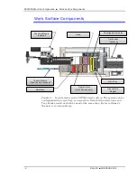
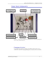
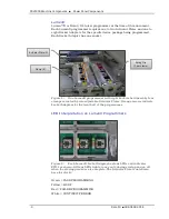
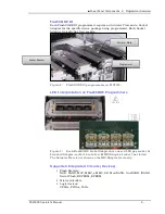
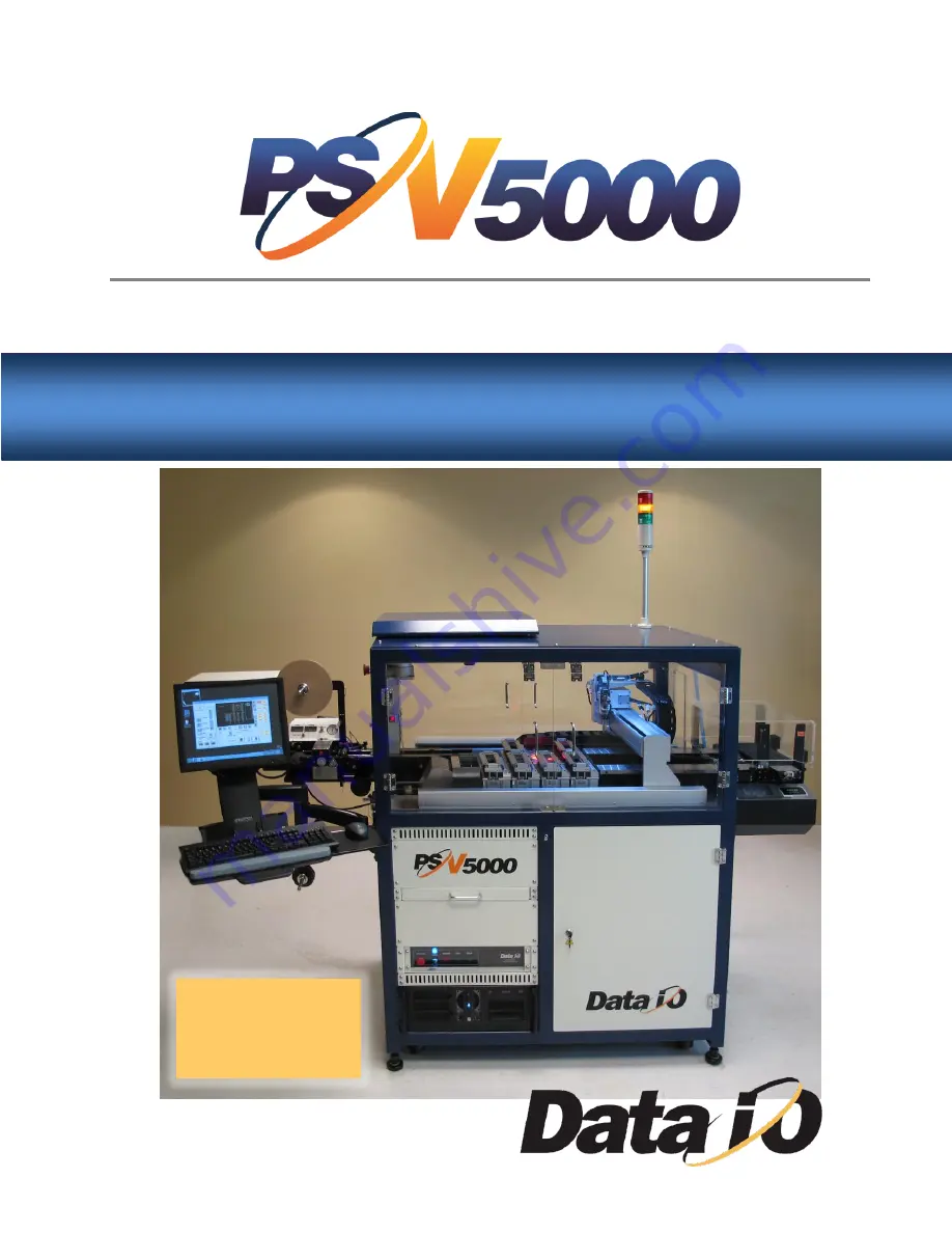
background image


Operator’s Manual 

Automated Programming and Handling 


096-0466-001E 

Now available   

with


LumenX Programmers 

Summary of Contents for PSV5000

Page 1: ...Operator s Manual Automated Programming and Handling 096 0466 001E Now available with LumenX Programmers...

Page 2: ...you for use in your application prior to use in a production environment Data I O does not warrant that the Data I O products will meet your requirements or that operation of the Data I O products wi...

Page 3: ...ystem 14 2 Installing Input Output Media 14 Setting Up Device Trays and Reject Bin 15 Installing the Tape In Module Option 18 Installing the Tape Rewind Module 21 Checking the Tape Output Option 23 3...

Page 4: ...Programmers 54 9 Optional Preselecting Programmers 56 10 Setting Media and Options the Setup Window 57 Verifying Media Setup 59 11 Starting Programming 61 Laser Marking 61 Removing Devices 64 Stoppin...

Page 5: ...atures and subassemblies on the machine Figure 1 Features of PSV5000 front top and back bottom Gantry Work surface Optional Tape Output Monitor and Keyboard Support for Tape Feeder Support for Option...

Page 6: ...can be configured with a reject tray or a reject bin Note that the static trays and Tray Feeder would not both be used at the same time Refer to Owner s Manual or on screen Help Tray alignment pins 3...

Page 7: ...mmer Overview Two programmer models are available for the PSV5000 both models can be in stalled next to each other but programming jobs can only be set to use one model Main Pressure Regulator AC powe...

Page 8: ...ith eight Sockets held down by four clamps actuated by two adjustable Actuator Plates Orange arrows indicate Socket Adapters for the front half of the programmer LED Interpretation on LumenX Programme...

Page 9: ...programmers on PSV5000 LED Interpretation on FlashCORE Programmers Figure 7 Each FlashCORE Socket Adapter has one red LED per socket A Standard Adapter socket 2 has failed B HIC Adapter Socket 3 has f...

Page 10: ...itched integrated circuits devices It accepts most package types The on screen applica tion that runs PSV5000 is CH700 Operator functions include installing some hardware checking hardware setup turni...

Page 11: ...to help avoid them Please read and heed the warning messages They look like the ones below Warnings and Cautions Special paragraphs with red lines are safety warnings as follows WARNING This is a war...

Page 12: ...o general General Hazard Warning Noise Warning may be over 80 db ADVERTENCIA de ruido puede ser m s de 80 decibeles L rm Warnung m glicherweise mehr als 80 Dezibel Eye Hazard Warning ADVERTENCIA de pe...

Page 13: ...front and one on the right side near back of the machine When an E Stop button is pressed the gantry stops moving immediately See the warning below To recover from an emergency stop see To Restart the...

Page 14: ...e a job is started WARNING Possible collision hazard The high speed and force of the gantry can seriously harm anyone working inside the workspace When working in the machine workspace moving the PNP...

Page 15: ...esigned to handle devices without damaging them CAUTION Possible device pin damage Do not touch devices with your hands or any implement other than the vacuum tool Doing so could damage devices with f...

Page 16: ...rected to do so in this manual Make sure that the machine is properly shut down before working on PSV5000 Do not place any part of your body into the direct path of moving parts Do not disable or atte...

Page 17: ...System List of Steps to Start a Job Operator functions are in chronological order as follows 1 Checking the System on page 14 2 Installing Input Output Media on page 14 3 Socket Adapters and Actuator...

Page 18: ...power turned ON or a process started even if the equipment was installed by another individual such as the administrator CAUTION Electrostatic discharge ESD hazard Wear an ESD strap or discharge stat...

Page 19: ...ed into the input tray and that they have the correct pin 1 orien tation If pin 1 orientation doesn t match pin 1 that is set in the Package File it must be corrected On the PSV5000 Pin 1 on Data I O...

Page 20: ...A reject bin may be used instead of a tray The reject bin can be installed at any programmer location Note that generally a reject bin and reject tray would not both be used Bevel Tray for reject outp...

Page 21: ...The chamfered corner should be next to the sensor 2 Push the tray snug against the locating pins on two sides and place the magnet at the corner opposite the rows of locating pins Figure 5 To install...

Page 22: ...The Tape Feeder installs on the left of the machine A safety plate covers the opening in the safety door when a feeder is not installed Figure 6 Possible layouts with tape input Top 5 FC programmers...

Page 23: ...move the two screws securing the small safety plate 3 mm hex key and remove the plate Refer to the figures above 3 Align the rail on the bottom of the feeder with the channel on the PSV5000 base plate...

Page 24: ...reel of devices onto the feeder see the documentation that came with your tape feeder 5 Pull the carrier tape forward to start it into the sprocket wheel on the tape feeder Now you can advance the car...

Page 25: ...Up frame to the front panel 2 Connect the power cable 3 Install the proper sized take up reel Figure 10 The Tape Rewind Take Up module on PSV5000 4 Power On the Tape Rewind and confirm the spindle st...

Page 26: ...ape Rewind is pulling too hard on empty carrier tape then decrease Tension The Tape Rewind module is ready for operation load your tape in feeder start your programming job and watch the Tape Rewind m...

Page 27: ...re the tape unwinds from the bottom of the spindle 2 Route the carrier tape by feeding it into the loading track Ensure the tape pockets are face down when first guiding the tape from the bottom Then...

Page 28: ...e the tape unwinds from the bottom 2 Route the cover tape by feeding it down into the loading track such that it meets with the carrier tape Figure 16 Routing the cover tape 3 Use adhesive tape to bin...

Page 29: ...parallel with the carrier tape 5 Run the machine to advance the tape through the sealer 6 Use adhesive tape to secure the end of the tape to the take up reel 7 On the left side of the controller box...

Page 30: ...ontrols 145 C recommended Figure 19 Temperature controls for heat sealer 3 Set the air pressure for the heat shoes 0 35 MPa recommended 4 On the touchscreen in the lower right corner of the Status scr...

Page 31: ...taper Figure 23 Adjusting the inner heat shoe position 10 Confirm that taped devices are securely held in the take up reel Perform a peel back peel force test by peeling the cover tape from the carri...

Page 32: ...the Control Panel ensure that Power is On but Heat is Off Figure 25 Ensuring the Heat button is OFF 2 On the touchscreen in the lower right corner of the Status screen press the Down arrow for the ne...

Page 33: ...To adjust the press sealer rollers pressure rotate a 3mm hex driver in the press sealer adjustment screw hole as depicted below Figure 28 Adjusting the pressure of press sealer roller 8 Confirm that...

Page 34: ...commend setting this counter to zero and using the pass quantity on the PSV5000 System to monitor quantity When the PSV5000 job is run devices are placed at the Tape Out pick point Ending a Run of Tap...

Page 35: ...e job If CH700 has not yet been started 1 Open TaskLink 2 Select your target job 3 Click Edit and then Footnotes Figure 30 Footnotes dialog in TaskLink lists the Socket Adapter Number If CH700 has alr...

Page 36: ...air does not shut off Operation of the machine should be the responsibility of one operator and all other people should not interact with the controls at the monitor which can trigger socket actuation...

Page 37: ...e 31 Remove the Actuator Plate by sliding it out from the bracket in either direction sockets must be closed up position If the programmer is between two others one of the adjacent Actuator Plates mus...

Page 38: ...on the programmer bracket and sliding in until it snaps into place Ensure it stops at the detents 7 See heading below ADJUST THE ACTUATOR PLATE unless you are using the same Socket Adapter as the pre...

Page 39: ...ng 5 With vacuum tweezers place a device into a socket to verify clearance between the bars 6 Before running the job or now if the power is already on cycle the ac tuator down and up to verify the set...

Page 40: ...discharge static against a common ground to prevent damage to Socket Adapters and devices 1 Pull the spring clip and lift open any socket clamp One clamp secures two Socket Adapters 2 Orient the Sock...

Page 41: ...X Programmers To adjust the Actuator Plates both types standard and HIC REQUIREMENTS Head is parked Actuator for the programmer is in the UP position sockets closed The nearest safety door is open 1 W...

Page 42: ...tips can be used with the new holders Pictured Right Basic components of a probe assembly on a PSV5000 pick and place PnP head Figure 37 Probe Assembly To identify the correct tip assembly for your ap...

Page 43: ...are Holder 6 1 288 0040 206 VACUUM CUP 6 10MM OD FOR 2 7MM TIP PSV 8 1 288 0040 208 VACUUM CUP 8 13MM OD FOR 2 7MM TIP PSV 10 2 288 0040 210 VACUUM CUP 10 16MM OD FOR 2 7MM TIP PSV 12 288 0040 212 VAC...

Page 44: ...RE PSV 2 7 6460171001 ProbeTip 1 9mm Square 6460172001 ProbeTip 2 7mm Square Figure 40 Different sized probe tips 3 Lastly select the appropriate Probe Tip Holder for your device Probes 6150321002 ASS...

Page 45: ...ve electrical power from the machine or any optional equipment Turn the main power OFF for safety unless otherwise directed 4 Push the head assembly down for access to the probe 5 IF A RETAINING CLIP...

Page 46: ...een installed yet 9 Optional but suggested Insert the Retaining Clip pushing it on making sure the aligning pin doesn t interfere 10 Make sure the tip is clean 11 Still at the Gantry window click Park...

Page 47: ...rrect Probes PSV5000 Operator s Manual 43 How to Teach a new TOOL Position 1 Click the Tool command in the Gantry window white arrow 2 Click any of the Arrow buttons circled in pur ple to move the hea...

Page 48: ...for most devices If you need dif ferent tips follow the steps below REQUIREMENTS No job is running 1 mm hex key Machine power will need to be turned OFF To remove and install Laser shuttle tips CAUTIO...

Page 49: ...location because Tray 1 is located within the PSV5000 interior workspace accessible by the PnP head B Gantry hardware and CH700 software handle the PnP movement of blank devices from Tray 1 to Program...

Page 50: ...d 2 To verify power ensure the top sensors have lights indicating power Figure 46 Verify sensor lights Verify Tray Feeder Initialization 1 Install up to 20 JEDEC trays of unprogrammed devices into the...

Page 51: ...dialog box click Misc I O Figure 48 Click Misc I O for Tray Feeder functions 6 In the I O Interface dialog box click the AutoTray tab then click Cycle Figure 49 Click AutoTray tab to cycle the Tray Fe...

Page 52: ...t pane 2 In the System window click Gantry Figure 50 Click Gantry for handler functions 3 In the Gantry window click Tr1 to move PnP head to the Tray 1 location Figure 51 Click TR1 to move PnP head to...

Page 53: ...e 53 Click X Y AutoFind to teach the horizontal position 7 If you see another confirmation dialog box about overwriting previous values click Yes to continue 8 Near the bottom middle section of the Ga...

Page 54: ...After PnP head moves to opposite corner of the tray click X Y AutoFind Figure 55 Click X Y AutoFind again to teach the opposite corner 11 If you see another confirmation dialog box about overwriting p...

Page 55: ...ure switch ON Make sure the pressure in dicator number is green Turning power ON does not start CH700 the PSV5000 automated handler software Although the CH700 icon on the monitor can be double clicke...

Page 56: ...bs To select and start a job for FlashCORE Programmers 1 At the touchscreen double click the TaskLink icon Figure 56 TaskLink icon 2 Open Task Manager select your Task from the list and click Run Figu...

Page 57: ...n are optional 7 When job setup is complete TaskLink confirms launching the CH700 software and displays the calculated checksum if Display Checksum option is checked in TaskLink Click Yes Figure 59 Cl...

Page 58: ...1 Double click the LumenX Data Management Software icon 2 Click your job name If no jobs display see the on screen Help for pointing LumenX to the correct directory 3 Click Select Figure 61 In main wi...

Page 59: ...ional View job details by clicking the Loaded Job drop down arrow LumenX DMS must be in PSV Mode for it to open CH700 Settings Settings set Presenter Mode to PSV Mode 6 Click Run Both TaskLink and Lum...

Page 60: ...een side of the Unlock Cnf button to allow changes 3 For each programmer click I green side of the button to enable it or the O red side to disable it If a programmer does not have a Socket Adapter or...

Page 61: ...esired Input Output and Reject media If using the Tray Feeder set Tray 1 to IN or IN and OUT as desired The Setup Options window may not distinguish between Tray 1 and Auto Tray To confirm that the wi...

Page 62: ...ional In the Continuity Retries field enter the number of times the system should retry continuity failures before rejecting the device b Optional In the Fail Retries field enter the number of times t...

Page 63: ...ntact Data I O Customer Support or a local Data I O approved service representative Verifying Media Setup 1 At the Setup window click the Job Info tab 2 Verify that all the information displayed for t...

Page 64: ...ancels any changes CAUTION Possible socket and device damage If an incorrect Package File was selected during Task creation or if device orientation was input incorrectly devices or socket contacts ma...

Page 65: ...that Tray 1 Tray 2 and Fail Tray have been found The PNP head begins its movements The Run window tracks head movement white square and displays device placement Socket status indicators appear insid...

Page 66: ...he driving source for optical scanning 6 Start the fume extractor see the next heading below 7 Start laser marking TaskLink loads the marking file set in the job file To stop the laser at any time pus...

Page 67: ...not running follow the steps below to turn the Fume Extractor power ON To manually start the Laser Fume extractor 1 Turn the PSV5000 power is OFF Refer to Turning Power OFF on page 74 2 Open the fron...

Page 68: ...ent of the PNP head immediately in an emergency Power to the gantry motors is disconnected and communication to the Laser head is disconnected The CH700 Application must be closed and the job re start...

Page 69: ...e gantry WARNING Electric shock and collision hazards Personal injury or machine damage can result if the Pause button is used for emergencies In an emergency do NOT use the on screen Pause button to...

Page 70: ...ing a Job To pause a job stopping the Gantry click Pause on the Run window Devices being programming will finish programming This is the preferred method for pausing the system in a non emergency situ...

Page 71: ...job prior to programming the preset number of devices click Finish on the Run Window This completes the current programming cycle No more blank devices are picked from the input media and all devices...

Page 72: ...tware exception Vacuum sensor malfunc tion Stopped Yellow Red alternat ing Operation is stopped due to error or operator action Operator intervention is mandatory to con tinue Correction may be throug...

Page 73: ...em Ending a Job PSV5000 Operator s Manual 69 Light Condition Action Required Possible Causes Machine Status Green Running normally No operator action needed Processing devices or clearing sockets to o...

Page 74: ...Run window click Pause 2 Right click on the target programmer and select All DISABLED All sockets on this programmer change to black and are effectively disabled To disable a single socket right clic...

Page 75: ...or one programmer while the Clear button on the Run window clears all sockets on the all programmers in use Figure 73 Right click a programmer in the Run window to change the status of the programmer...

Page 76: ...____________ __________________ __________________ __________________ Tape Tray Tube Tape Tray Tube Laser Mark 3D Inspect VX 3D Inspect UX Reject Type _____________ __________________ ________________...

Page 77: ...Inspect UX Reject Type _____________ __________________ __________________ __________________ Tape Tray Tube Tape Tray Tube Laser Mark 3D Inspect VX 3D Inspect UX Reject Type _____________ ___________...

Page 78: ...CAUTION Possible damage to programmers and devices DO NOT TURN POWER OFF to the programmers or to the PSV5000 Machine while a job is running A job must be Finished before turning programmer power OFF...

Page 79: ...e Key switch OFF counterclockwise Figure 74 Laser Control Panel d WAIT UNTIL WINDOWS COMPLETES SHUTTING DOWN and then rotate the main power switch on the PSV5000 Power Panel OFF counterclockwise e Opt...

Page 80: ...r to clicking Start in CH700 install up to 20 JEDEC trays of un programmed devices into the Input Stack of the Tray Feeder 3 Start a PSV5000 job through TaskLink Tray Feeder loads the first tray 4 In...

Page 81: ...taio CollectLogs Programmer Related Problems When you experience a programmer related problem 1 Force the error to re appear by running a job or performing the same steps that led to the trouble 2 Clo...

Page 82: ...My Notes Collecting System Logs 78 Data I O 096 0466 001E My Notes...

Page 83: ...nfiguring input output settings 57 cover tape 24 alignment 24 routing 24 D Data I O contacts See inside back cover Devices handling 11 dwell time 26 E Emergency Stop button locations 9 function 65 res...

Page 84: ...r 42 Disabling a programmer disabling 70 Programmer locking configuration 56 One Model only Rule 31 Overview 3 pre selecting 56 Programmer disabling 70 R Removing Actuator Plate 32 Removing devices 64...

Page 85: ...ape Rewind 21 Tape Take Up 21 tape width 25 Taper carrier tape 23 cover tape 24 heat sealer 26 press sealer 28 TaskLink loading a job 51 starting 52 Technical Support See inside back cover test peel b...

Page 86: ...82 Data I O 096 0466 001E...

Page 87: ...mber at the Power Panel Software Version lower right corner of CH700 Tray Feeder Serial Number if Tray Feeder related Detailed description of the problem you are experiencing if any Error messages if...

Page 88: ...Data I O 096 0466 001E Programmable Media Experts www dataio com www dataio de www dataio cn...

Reviews: