background image

The Data Industrial Series 340 Btu transmitter is an economical, compact device for sub-metering
applications.

The 340 calculates thermal energy by measuring liquid flow in a closed pipe system and measuring
temperature at inlet and outlet points. The 340 requires two 10 k

 thermistors for temperature input.

The flow input may be provided by any Data Industrial sensor and many other pulse or sine wave signal
flow sensors.

The onboard microcontroller and digital circuitry make precise measurements and produce accurate
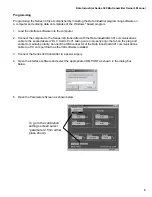
drift-free outputs. The 340 is programmed using Data Industrial’s Windows

 based software and a Data

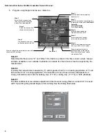
Industrial A301 programming cable.  Calibration information for the flow sensor, units of measurement
and output scaling may be downloaded prior to installation or in the field.  While the unit is connected to
a PC or laptop computer, real-time flow rate, flow total, both temperature readings, energy rate and
energy total are available.

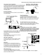
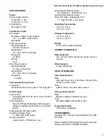
The Series 340 transmitter features two LED’s to verify input and output signals.

The standard output for the Series 340 is an isolated solid state switch closure that is user programmed
for units of energy or flow.  The output pulse width is adjustable from 50 mS to 5 sec.

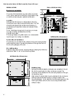
The Series 340 Btu transmitter operates on AC or DC power supplies ranging from 12 to 24 volts.

The compact cast epoxy body measures 3.65”(93mm) x 2.95”(75mm) and can be easily mounted on
panels, DIN rails or enclosures.

Series 340

Btu transmitter

by Data Industrial

Owner ’s

Manual

PN# 72032
REV D     08/22/01

®

Data

Industrial

DATA INDUSTRIAL CORPORATION 

11 Industrial Drive, P.O. Box 740 Mattapoisett, MA  02739-0740 USA

Phone: (508) 758-6390    FAX: (508) 758-4057   email: sales@dataindustrial.com

Sen
so

r I

npu

t

Power Out
Signal 

+

Signal 

-

Shield

Po

w

er I

n

AC L/DC 

+

AC C/DC

-

Ou
tp

ut

Pulse Out

-

Pulse Out

+

Te

m

p 2

Te

m

p 1

Output LED

Model: 340

S/N 340-XXXXX

®

Input LED

Mattapoisett, MA 02739

D.

I.C

.

Co
m

m

Po

rt

Summary of Contents for 340 Series

Page 1: ...puter real time flow rate flow total both temperature readings energy rate and energy total are available The Series 340 transmitter features two LED s to verify input and output signals The standard output for the Series 340 is an isolated solid state switch closure that is user programmed for units of energy or flow The output pulse width is adjustable from 50 mS to 5 sec The Series 340 Btu tran...

Page 2: ...ment of the programming cable The unit generates very little heat so no consideration need be given to cooling or ventilation Surface Mount Installation The 340 may be mounted to the surface of any panel using double sided adhesive tape or by attaching fasteners through the holes in the mounting flanges of the unit Din rail Mounting Optional clips snap onto the mounting flanges allowing the 340 to...

Page 3: ...is used connect the black white striped wire to the terminal marked positive and the black wire to the terminal marked negative Note Included with every Series 340 is a 340IK kit containing a screw lock washer and nut to connect the Series 340 to Earth Ground Connect the Earth Ground Lug of the Series 340 to a solid Earth Ground with as short a wire as possible This will help prevent electrical in...

Page 4: ...rve the electrical polarity of the output Communications cable wiring Field calibration requires a Data Industrial A340 Programming kit consisting of a custom cable and software and a PC running Windows 9x ME NT or 2000 In order to calibrate the Series 340 must be connected to power and the A301 cable must be connected to the 340 Comm port connector and an available 9 pin COM port on a computer No...

Page 5: ...ustrial A 301 communications cable to the socket labeled D I C Comm Port taking care to properly align the tab on the plug and socket to maintain polarity Connect the DB9 connector of the Data Industrial A301 communications cable to a PC com port that has the 340 software installed 3 Connect the Series 340 transmitter to a power supply 4 Open the interface software and select the appropriate COM P...

Page 6: ...ed with 10 providing the greatest degree of smoothing See the Dialog Box below 6 Program using diagram below as a reference Step 1 see note 1 Select the flow sensor type sine or pulse and enter the k and offset Step 4 Select the desired flow rate and total units here Step 7 Press send to transmit calibration data to the 340 Step 5 Select the desired energy rate and total units here Step 2 Select t...

Page 7: ...ce Opto isolated solid state switch Operating Voltage range 0 60V DC or AC peak Closed on state Load Current 700mA max over operating temperature range On resistance 700mΩ max over operating temperature range Open off state leakage 70 C 1 A 60V DC or AC peak Operating Temperature 29 C to 70 C 20 F to 158 F Storage Temperature 40 C to 85 C 40 F to 185 F Weight 4 8 oz With headers installed SENSOR C...

Page 8: ... a Version n a Temperature Units F Sensor Type Pulse K 1 offset 0 Flow Rate Units gpm Flow Total Units gallons Energy Rate Units kBtu hr Energy Total Units Btu Energy Calculation absolute Flow Filter 0 Energy Filter 0 Scaled Pulse Output Units energy Scaled Pulse Output Units Per Pulse 1 Scaled Pulse Output Pulse Width 100 ...

Page 9: ...ress Seller may at its sole option instruct Buyer to ship subject part postage prepaid to the Seller at above address or authorize a representative to inspect the part on site Seller will at its sole option repair or replace any defective product covered by this warranty If Buyer makes repairs or alterations to any product or part covered by this warranty without Sellers prior written approval thi...

Reviews: