background image


Datacolor 200


Summary of Contents for 200

Page 1: ...Datacolor 200 ...

Page 2: ...color Datacolor 200 SPECTRUM and other Datacolor product trademarks are the property of Datacolor Microsoft and Windows are either registered trademarks of Microsoft Corporation in the United States and or other countries To obtain information on local agents contact either of the offices listed below or visit our website at www datacolor com Support Questions If you need help with a Datacolor pro...

Page 3: ...s Panel 6 Powering Up 6 Instrument Calibration 7 General Calibration Information 7 Datacolor 200 Setup and Calibration 8 Instrument Setup for Datacolor PAINT 8 Datacolor PAINT Instrument Calibration 9 Setup and Calibration for Other Datacolor Programs 9 Sample Presentation and Measurement 13 Sample Viewing Port 14 Maintenance 15 SphereCleaning 15 Tile Handling and Cleaning 15 Appendix 17 Datacolor...

Page 4: ... Datacolor 200 User Guide This page intentionally left blank ...

Page 5: ...A Absolute Operating Environment 5º to 40º C 20 85 RH non condensing Altitude up to 2 000 meters Safety Warnings If the equipment is used in a manner not specified by the manufacturer the protection provided by the equipment may be impaired CAUTION There are no user serviceable parts for this equipment Light Source Do not stare directly into the open port located in the front door panel when the m...

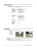
Page 6: ...metry specular component included SCI or excluded SCE SP2000 Spectral Analyzer Proprietary dual channel holographic grating 256 photodiode linear arrays used for both the reference and sample channels Light source Pulsed xenon flash lamp Wavelength Resolution 2 nm Reporting Interval 10nm Accessories All models come with the following standard accessories Power cable USB cable Black trap White tile...

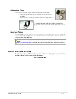
Page 7: ...hen not in use Aperture Plates Datacolor 200 is a single aperture instrument However a variety of aperture sizes are available to accommodate different applications Consult with a Datacolor representative to determine the correct aperture size for your application NOTE Appendix Instrument Specifications provides details about the aperture sizes available for Datacolor 200 About This User s Guide T...

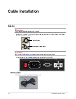
Page 8: ...ment cable that connects the instrument to the computer WARNING Refer to Electrical Environmental Requirements before connecting the instrument The connections for these cables are located on the back of the instrument Power Cable A six foot power cable is provided with the instrument Power Cable Instrument Cable USB Power Switch Power Connection Serial Connection USB Connection ...

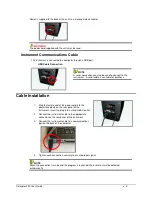
Page 9: ...erial cable is available for purchase Cable Installation 1 Plug the female end of the power cord into the power receptacle on the rear panel of the instrument Insert the plug into a standard AC outlet 2 Connect the instrument cable to the appropriate connector on the rear panel of the instrument 3 Connect the instrument cable to a communications port on the back of the computer 4 Tighten each conn...

Page 10: ...ended Green Instrument is performing properly Powering Up WARNING The power cord supplied with the unit must be used 1 Verify all cable connections 2 Plug the AC power cord into an outlet 3 Attach the instrument cable to the instrument and to a port on the computer 4 Turn on the computer 5 Turn on the power switch It is the red switch on the back of the instrument 6 When power is applied all mecha...

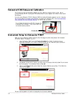
Page 11: ...mpensate for changes in the environment A black trap white tile and green tile are included with the instruments The software prompts for instrument calibration vary slightly from one program to another However you are always required to measure the black trap white tile and green tile to complete the calibration NOTE The recommended calibration interval may vary depending upon the Datacolor appli...

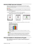
Page 12: ...olor PAINT for the first time the program automatically detects the Datacolor 200 and configures the program to use it 1 Launch Datacolor PAINT and select Custom Color Match Initially there will not be any information displayed in the Instrument Information box and the Calibration Status will be red 2 The program will locate the instrument and the screen will display information about the instrume...

Page 13: ...t is completed repeat this procedure for the white and green tiles 2 When the green tile measurement is completed the program displays information about the measurement 3 Click Ok The program stores this as the master measurement for the green tile You can now measure samples NOTE Each time the instrument is calibrated the current green tile measurement is compared to the stored value When there a...

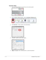
Page 14: ... the user name and password 2 The main program window will display Select the Instrument Calibration option 3 Select Calibration The measurement main window displays 4 Click Add The Add Instrument window displays 5 Display the drop down menu in the Model field and scroll to Datacolor 200 ...

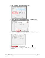
Page 15: ...arch for the device and display the com port assignment 8 Click Add Datacolor 200 will display as the current instrument At the bottom of the window the program will display information about the instrument selected 9 Click Close The Measurement Main Window displays You can now calibrate the instrument Instrument information ...

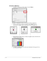
Page 16: ...green tile 2 Start with the black trap Position it at the port and press Ready When the measurement is completed repeat this procedure for the white and green tiles 3 When the green tile measurement is completed the program displays information about the green tile measurement 4 Click OK The program stores this as the master measurement for the green tile You can now measure samples ...

Page 17: ...sure an accurate measurement When positioned correctly the sample rests between the sample holder and the front panel door The sample must completely cover the aperture opening To position the sample 1 Grasp the sample holder and pull forward 2 Position the sample at the port 3 Return the sample holder to the upright position WARNING Do not allow the sample arm to spring back ...

Page 18: ...asp the tab above the aperture plate 2 Pull the tab down to its full horizontal position Look at the backside of the door to see the area of the port opening that is covered by the sample If necessary adjust the placement of the sample to properly position the sample area to be measured The sample must completely cover the port opening 3 Push the door back to its normal position and start the meas...

Page 19: ...nce of dust sample particles fibers and excessive yellowing due to environmental influences This inspection should be performed frequently especially if you measure loose materials NOTE If you discover loose materials in the sphere contact Datacolor Service for instructions to remove the loose material Tile Handling and Cleaning Handling Tiles Handle calibration tiles with extreme care Do not drop...

Page 20: ... the tile surface NEVER immerse the tiles in water Tiles that have scratches chips abrasions or cracks must be replaced Signs of wear on the tile surface will affect the accuracy of the calibration Tile Storage Large temperature variations will affect the accuracy of your calibration requiring more frequent calibration The calibration tiles should be stored in an environment that simulates the tem...

Page 21: ... 2nm Photometric Range 0 to 200 Photometric Resolution 0 003 Aperture Configuration Large Area View Small Area View Ultra Small Area View Illuminated 22mm Viewed 18mm Illuminated 9mm Viewed 5mm Illuminated 6 5mm Viewed 2 5mm Power 100 to 240 VAC 50 to 60 Hz 1 A Performance Repeatability 0 05 CIELAB Max on white ceramic Performance Reproducibility 0 2 CIELAB ΔE average of 12 BCRA tiles Absolute Ope...

Page 22: ...Information Datacolor 200 RS 232C Connector Pin Assignments Pin Purpose Direction 2 Transmit data Out to host 3 Receive data In from host 7 Signal ground WARNING 1 DO NOT WIRE to pins other than 2 3 and 7 2 For all unused inputs the default is active high ...

Reviews: