background image


The DFC-0115 is an advanced, precision 
15 step power factor control and metering 
device, which continuously matches the 
target cosø value of the load. 
Installation and configuration of the DFC-
0115 is very simple thanks to the auto-
learning function.  

Each step output supports single-phase, 
two-phase, and three-phase connection of 
capacitors and reactors.  


Electrical equipment should be installed only 

by qualified specialist. No responsibility is 
assured by the manufacturer or any of its 
subsidiaries for any consequences resulting 
from the non-compliance to these 
instructions.  

  Check the unit for cracks and damages due 

to transportation. Do not install damaged 
equipment. 

  Do not open the unit. There is no 

serviceable parts inside. 

  Fuses of fast type with a maximum rating of 

6A must be connected to the power supply 
and phase voltage inputs, in close proximity 
of the unit. 


  Disconnect all power before working on 

equipment.


  When the unit is connected to the network 

do not touch terminals. 


  Short circuit terminals of unused current 

transformers. 


  Any electrical parameter applied to the 

device must be in the range specified in the 
user manual.


  Do not try to clean the device with solvent or 

the like. Only clean with a dump cloth. 


  Do not allow water to come in the unit. 


  Verify correct terminal connections before 

applying power.


  Only for front panel mounting.


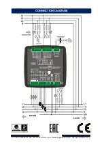
Before Installation: 

  Read the user manual carefully, 

determine the correct connection 
diagram.   

  Remove all connectors and mounting 

brackets from the unit, then pass the 
unit through the mounting opening.   

  Put mounting brackets and tighten. Do 

not tighten too much, this can break 
the enclosure.   

  Make electrical connections with plugs 

removed from sockets, then place 
plugs to their sockets.   

  Make sure to use adequate fuses.  

  Do not subject the unit to water spill. 


Below conditions may damage the 
device:


  Incorrect connections.   

  Incorrect power supply voltage.  

  Voltage at measuring terminals 

beyond specified range.   

  Current at measuring terminals 

beyond specified range.  

  Overloaded or short circuited relay 

output terminals. 


Below conditions may cause abnormal 
operation: 

  Power supply voltage below minimum 

acceptable level.  

  Power supply frequency out of 

specified limits   

  Phase order of voltage inputs not 

correct. (Without auto-correct function)  

  Current transformers not matching 

related phases. (Without auto-correct 
function) 

  Incorrect current transformer polarity. 

(Without auto-correct function)  

  Inappropriate delay for switch on, 

switch off delays of steps. 
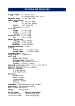


            DFC-0115 

REACTIVE POWER CONTROLLER 
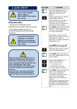


SAFETY NOTICE 
Failure to follow below 
instructions will result in 
death or serious injury


INSTALLATION


Current transformers must 
be used for current 
measurements. No direct 
connection allowed. 


Summary of Contents for DFC-0115

Page 1: ...e unit Verify correct terminal connections before applying power Only for front panel mounting Before Installation Read the user manual carefully determine the correct connection diagram Remove all connectors and mounting brackets from the unit then pass the unit through the mounting opening Put mounting brackets and tighten Do not tighten too much this can break the enclosure Make electrical conn...

Page 2: ...roportionally Current transformers must have a 5A output Three buttons on the front panel provide access to configuration and measurement screens BUTTON FUNCTION Remove all alarms in AUTO mode If the same alarm occurs again it will not be displayed When held pressed for 3 seconds Programming mode activated All alarms are enabled Skip to the next parameter Measurement and parameter screen Increase ...

Page 3: ...nce more to see value of LErn parameter Will be 0 as default Adjust value of LErn to 1 by clicking up arrow button 1 Auto setup 3 2 2 Step values learning 3 CT connection correction Click MENU button to enable auto setup Device will check and correct current transformer connections After that reactive power of each step will be measured by the auto learning function After successful auto setup AUT...

Page 4: ...n is held pressed When the required password is set click MENU button First parameter should be seen LErn if correct password is typed Hold down MENU button for 3 seconds and LAMP TEST mode will be activated All LEDs on the device will turn on Click MENU button again to navigate through measurement screens BUTTON FUNCTION Choose required parameter by using up and down arrows while parameter can be...

Page 5: ... 1 FCty Return to factory settings When this parameter is set to 1 all parameters will return to their factory set values 0 0 1 DEFINITION MIN STD MAX CtrF Current Transformer Primary value of current transformers Can be set between 5 5A and 5000 5A 5A 500A 5000A CoS Target Cosø Target Cosø can be set between capacitive 0 800 and inductive 0 800 Capacitive power factor is displayed as c 800 while ...

Page 6: ...calculated at the end of this delay 1 sec 1 sec 2000 sec t CL Step switching protection delay When the unit sets a new step configuration all step switching will be disabled during this timer 0 sec 1 sec 2000 sec dCHr Discharge timer This is the common discharge timer for all steps Any step swithed off cannot be switched on again before expiration of this timer 3 sec 14 sec 2000 sec ...

Page 7: ...se Current Inputs 0 5VA per phase Number of Steps 12 15 Relay Outputs 5A 250V A Serial Port Signal Type RS 485 Communication Modbus RTU Baud Rate 2400 115200 selectable Isolation 500V AC 1 minute Operating Temperature 20 C to 70 C 4 to 158 F Maximum Humidity 95 non condensing Degree of Protection IP 54 Front Panel IP 30 Rear Panell Enclosure Non flammable ROHS compliant Flame retardant High temp A...

Page 8: ...Tel 90 216 466 84 60 Fax 90 216 364 65 65 e mail datakom datakom com tr http www datakom com tr CONNECTION DIAGRAM ...

Reviews: