


Summary of Contents for C-BOX 100
Page 1: ...C BOX 100 Installation Manual...
Page 2: ...C BOX 100 Installation Manual...
Page 3: ...C BOX 100 INSTALLATION MANUAL...
Page 10: ...viii...
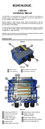
The Datalogic C-BOX 100 streamlines setup with its user-friendly design. Get up and running fast by downloading the free Installation Manual. Ensuring proper setup and troubleshooting, the manual is essential for all users. Access your free manual by visiting 88.208.23.73:8080 for a hassle-free download.
Page 1: ...C BOX 100 Installation Manual...
Page 2: ...C BOX 100 Installation Manual...
Page 3: ...C BOX 100 INSTALLATION MANUAL...
Page 10: ...viii...