background image

LGS-N50

USER MANUAL

Navigation LiDAR

Preliminary 13-Jan-2021

Summary of Contents for LGS-N50

Page 1: ...LGS N50 USER MANUAL Navigation LiDAR Preliminary 13 Jan 2021 ...

Page 2: ...documentation Electronic versions of this document may be downloaded from the Datalogic website www datalogic com If you visit our website and would like to make comments or suggestions about this or other Datalogic pub lications please let us know via the Contact page Disclaimer Datalogic has taken reasonable measures to provide information in this manual that is complete and accu rate however Da...

Page 3: ...thernet connector 7 Communication 7 LEDs 9 DATA PACKET FORMAT 10 Overview 10 Definition of Header 11 Definition of Block 11 Data conversion 12 Angle calculation 12 Distance calculation 12 Calculation of signal strength 12 PARAMETER CONFIGURATION 13 Web server configuration 13 configuration through LGS Viewer PC software 14 Operating environment 14 Network environment 14 LGS Viewer Windows Firewall...

Page 4: ... and type in the name of the product you re looking for This allows you access to download Data Sheets Manu als Software Utilities and Drawings Hover over the Support Service menu for access to Services and Technical Support Reseller Technical Support An excellent source for technical assistance and information is an authorized Datalogic reseller A reseller is acquainted with specific types of bus...

Page 5: ...information prop erlyfor future reference Pay attention to the warnings please read all the warnings in the manuals and on the product carefully Follow the instructions please follow all the operation instructions in this manual Maintenance instructions please follow the instructions for troubleshooting do not try to repair the equipment by yourself Contact our technicians promptly to solve the pr...

Page 6: ...s removed and the operator would be exposed to laser CAUTION It is not guaranteed that the laser remains Class 1 safety status after open ing the cover CAUTION Disconnect the power supply when connecting or disconnecting electrical cables CAUTION The power supply connected with the device must comply with the require ments included in the operation instructions CAUTION Please connect the reference...

Page 7: ...hen returns the amount of returned laser energy depends on the reflectivity of objects The LiDAR obtains the detected distance and angle information through calculation as shown below Figure 1 LGS N50 LiDAR working principle Based on the TOF Time of Flight principle the distance between objects and LiDAR is obtained according to the speed of light and time of flight of the laser The calculation me...

Page 8: ...CONNECTION LGS N50 LiDAR can be installed in two ways back mounting and base mounting Back mounting There are four M5 screw holes at the back of the main frame for installation hole depth 8mm Figure 2 LGS N50 Back Mounting interface Preliminary 13 Jan 2021 ...

Page 9: ... of the main frame for installation hole depth 8mm Figure 3 LGS N50 Base Mounting interface ELECTRICAL CONNECTION There are three connectors on the back of LGS N50 for power supply I O and 4PIN Ethernet connection respectively as shown below Figure 4 LGS N50 Connection Preliminary 13 Jan 2021 ...

Page 10: ...ons are as follows 1 Vcc Brown 2 Q2 White 3 GND Blue 4 Q1 Black Figure 5 Power connector I O connector The pin definitions of the I O connector are shown below 1 n c 2 n c 3 n c 4 n c 5 n c 6 n c 7 n c 8 n c Figure 6 I O connector No DEFINITION WIRING COLOR No DEFINITION WIRING COLOR Preliminary 13 Jan 2021 ...

Page 11: ...t prior to establishing communication Both the LiDAR and the computer IP addresses must be set within the same subnet without con flicting with each other The point cloud packet receiving port number is 2368 The IP address setup process is shown below Computer IP 192 168 1 10 Computer subnet mask 255 255 255 0 Factory default of LiDAR is as follows LiDAR IP 192 168 1 100 LiDAR subnet mask 255 255 ...

Page 12: ...INSTALLATION AND USAGE 8 LGS N50 Figure 9 Computer IP Setting Step 2 Figure 10 Computer IP Setting Step 3 Preliminary 13 Jan 2021 ...

Page 13: ...n Q1 such as motor block voltage out of specifications etc According to the internal diagnostic system if some critical diagnostic test fails Q2 blinks and the ERR LED lights up steadily ERR Shows the status of device availability If switched off then the device is in normal operation If it s steadily on then it shows an error condition see Q1 and Q2 If it s blinking it indicates that the device i...

Page 14: ... format with low byte at the front and high byte at the end OVERVIEW Total length of data packet is 1240 bytes among which the header has 40 bytes data returned by laser has 1200 bytes Figure 12 Format of point cloud information packet The total length of a data frame is 1240 byes including Frame header 40 bytes Data block 150 x 8 1200 bytes Preliminary 13 Jan 2021 ...

Page 15: ...Rotation rate Bit15 Rotation direction 0 clockwise 1 counterclockwise 34 1 Safe zone status same as the hardware INPUT OUTPUT BIT 3 0 Same as OUTPUT 3 0 BIT 7 4 Same as INPUT 3 0 35 1 Error status A corresponding bit of 1 indicates an error BIT0 Motor fault BIT1 Abnormal voltage BIT2 Temperature fault 36 4 Reserved DEFINITION OF BLOCK The length of data block is 8 bytes as shown in the table below...

Page 16: ...ate the distance of LGS N50 follow the example below 1 Obtain distance value 0x11 0x12 2 Swap high bits and low bits 0x12 0x11 3 Combine into an unsigned hexadecimal number 0x1211 4 Convert to decimal 4625 5 Multiply by minimum resolution 1mm 6 Result 4625mm Calculation of signal strength To calculate the signal strength of LGS N50 follow the example below 1 Obtain signal strength value 0x11 0x12 ...

Page 17: ...tion of spe cific modules inside When the parameter font turns red the LiDAR may not be working properly The current LiDAR settings are automatically loaded when the page is refreshed Select the required speed value by Motor RPM 600 900 1200 1500 correspond ing to the 10 15 20 25Hz LiDAR scanning frequency confirm by clicking Set Con figs Turn on off DHCP if ON then LiDAR dynamically obtains the I...

Page 18: ... follows OS Windows 7 and above NET Framework 4 5 2 Pcap wpcap runtime Network environment The default factory static IP for LiDAR is as follows LiDAR IP 192 168 1 100 Net mask 255 255 255 0 The web page setting interface and PC software interface may change due to product update If Windows Firewall is active on the configuration PC a pop up window will appear Follow the procedure described in LGS...

Page 19: ... window before allowing access to both private and public networks of the PC to communicate and exchange data with the device through the Ethernet port If you close the pop up window before confirming the Firewall authorization go to Con trol Panel System and Security Windows Defender Firewall Allowed apps and click on Change settings If no firewall window appears but an Unable to connect message ...

Page 20: ...er measure data Alternatively go to File Open Capture File Select Sensor select and connect a scanner to read its measure data in real time Alternatively go to File Open Select Sensor Color Coding change the color coding representing the intensity value for each point being displayed The software will provide scheme level graphics in the Color directory that loads the root at initialization The gr...

Page 21: ...onfig software program can be used to restore the following settings to fac tory configuration IP 192 168 1 100 Host 192 168 1 100 2368 From the LGS Viewer software program go to Tool ResetConfig or launch the Reset Config software program The following window is displayed Click on the Reset S but ton to restore settings to factory configuration Figure 15 ResetConfig software program Preliminary 1...

Page 22: ...odule To upgrade the firmware follow the procedure below 1 Click on the gray box to the right and select the ldrup firmware file or drag it to the specified area 2 Click on the Upgrade button 3 Open the LiDAR default configuration web page and check that the firmware has been upgraded Preliminary 13 Jan 2021 ...

Page 23: ...lution 1 mm Interface type IEEE 802 3u 100Mbps Ethernet Protocol UDP IP Operation voltage 12 to 32 VDC Power consumption 25 C 7 W 15 Hz Absolute accuracy 30 mm 90 WB Repeat accuracy 20 mm 90 WB Angle resolution 0 06 10 Hz 0 09 15 Hz 0 12 20 Hz 0 15 25 Hz USER MANUAL 19 CHAPTER 7 TECHNICAL PARAMETERS GENERAL SPECIFICATIONS INTERFACE ELECTRICAL SPECIFICATIONS MEASUREMENT ACCURACY Preliminary 13 Jan ...

Page 24: ... aluminum Window polycarbonate Panel and LED cover polycarbonate and ABS Mass 900 g Vibration IEC 60068 2 6 Shock IEC 60068 2 27 EMC IEC 61000 6 2 IEC 61000 6 3 Laser safety IEC 60825 1 ROHS Safety requirements UL61010 1 pending LED indicator RGB 4 Color Operation indicator Green LED Power ON Function indicator Red LED LiDAR fault Basic software Datalogic LGS Viewer TECHNICAL PARAMETERS 20 LGS N50...

Page 25: ...tting of the data receiver Try to use a third party data capture tool to check whether data can be obtained normally Check whether only one LiDAR software is started Check whether the data receiver has any safety soft ware or process that is blocking data transmission If failure persists contact Datalogic Technical Support USER MANUAL 21 CHAPTER 8 TROUBLESHOOTING PROBLEM SOLUTION Preliminary 13 Ja...

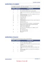
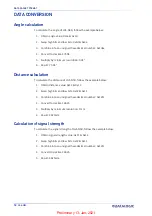
Page 26: ...22 LGS N50 APPENDIX A DATA PACKET Preliminary 13 Jan 2021 ...

Page 27: ...USER MANUAL 23 APPENDIX B MECHANICAL DIMENSIONS Preliminary 13 Jan 2021 ...

Page 28: ...MECHANICAL DIMENSIONS 24 LGS N50 Preliminary 13 Jan 2021 ...

Page 29: ...USER MANUAL 25 APPENDIX C EXAMPLE OF ELECTRICAL CONNECTION OUTPUT Q1 Preliminary 13 Jan 2021 ...

Page 30: ...Preliminary 13 Jan 2021 ...

Page 31: ...Preliminary 13 Jan 2021 ...

Page 32: ...of this documentation may be reproduced stored in or introduced into a retrieval system or transmitted in any form or by any means or for any purpose without the express written permission of Datalogic S p A and or its affiliates Datalogic and the Datalogic logo are registered trade marks of Datalogic S p A in many countries including the U S and the E U www datalogic com 821007250 Rev A January 2...

Reviews: