background image

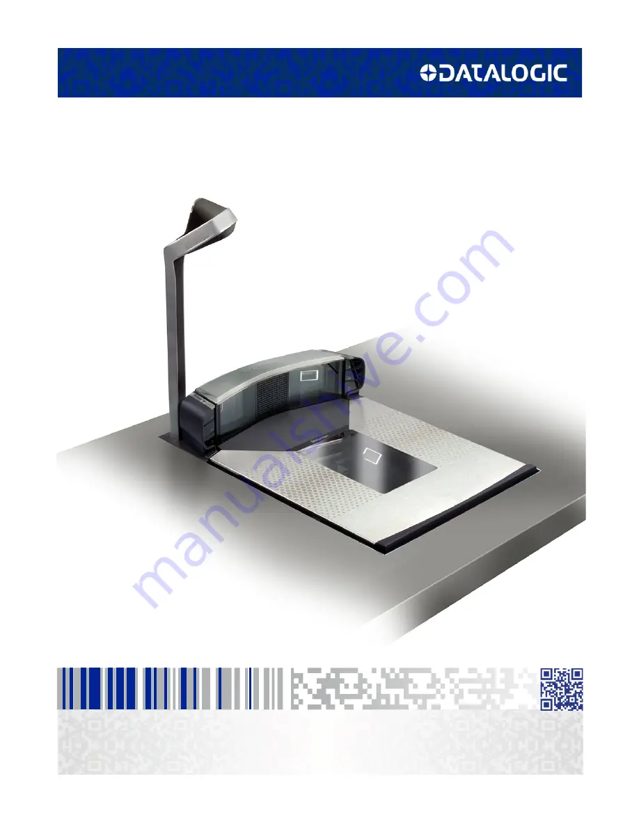
Magellan

TM

 9800i

Product Reference Guide

Summary of Contents for Magellan 9800i

Page 1: ...MagellanTM 9800i Product Reference Guide...

Page 2: ...c page Disclaimer Datalogic has taken reasonable measures to provide information in this manual that is complete and accurate however Datalogic reserves the right to change any specification at any ti...

Page 3: ...abeling 12 Agency Compliances 13 Bar Codes Supported 15 1D Symbologies 15 2D Symbologies 15 Technical Support 16 Datalogic Website Support 16 Reseller Technical Support 16 Telephone Technical Support...

Page 4: ...enance 51 Scanning Items 51 Proper Weighing Technique Scale Models 52 Deactivating Security Labels 53 Operational Controls 54 Operational Modes 54 Power Up Selftest Pre Operation 54 Operating Mode 55...

Page 5: ...ng Programming Mode 94 Programming Session 95 Programming Sequence 96 LED and Beeper Indicators 98 If You Make a Mistake 98 Test Mode 99 Chapter 8 Imaging Features 101 Top Down Reader TDR and Mobile C...

Page 6: ...ductivity Index Reporting PIR Cashier Training CT 143 PIR CT Auxiliary Port Baud Rate 144 Chapter 10 EAS Features 147 EAS Features Sensormatic 147 EAS Mode 148 EAS Notification 150 EAS Security Level...

Page 7: ...Value 196 RS 232 ACK NAK Retry Count 197 RS 232 ACK NAK Error Handling 198 RS 232 Indicate Transmission Failure 199 Single Cable RS 232 Options 200 Single Cable RS 232 Scanner Only Protocol 201 Single...

Page 8: ...ion 244 Expand UPC E to UPC A 245 Expand UPC E to EAN 13 246 UPC E Minimum Read 247 EAN 13 Enable 248 EAN 13 First Character Transmission 249 EAN 13 Check Character Transmission 250 EAN 13 ISBN Conver...

Page 9: ...ion 296 Code 39 Full ASCII 297 Code 39 Minimum Read 298 Code 39 Correlation 299 Code 39 Length Control 300 Code 39 Length 1 301 Code 39 Length 2 302 Code 39 Stitching 303 Code 39 Require Margins 304 C...

Page 10: ...Calculation 348 MSI Number of Check Characters 349 MSI Check Character Transmission 350 MSI Minimum Read 351 MSI Correlation 352 MSI Length Control 353 MSI Length 1 354 MSI Length 2 355 MSI Stitching...

Page 11: ...ndicators 389 Controls and Indicators 390 LED and Audio Indications 391 ScaleSentry Scale Service Button 394 Sensormatic EAS Button 395 Camera Button 395 Mobile Commerce Button 395 Scanner Control But...

Page 12: ...x Magellan 9800i Scanner Appendix G Handheld Data Format Requirements 427 Handheld Data Format Requirements General 427 Datalogic Handheld Data Format Requirements 428 AIM Formats 433...

Page 13: ...nd operation of the scanner or scanning scale NOTE For the purposes of this manual any Magellan 98xx model may be termed as simply scanner including scanning scale models Because of differences due to...

Page 14: ...em problem and troubleshooting flowcharts to aid in problem resolution are also presented Chapter 6 Calibration Procedures explains scale calibration and verification procedures including procedures f...

Page 15: ...They provide information that is critical to operations and or procedures described in this man ual LEGAL NOTE LEGAL NOTE blocks indicate procedures or activities which may be regulated under law by...

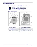
Page 16: ...Electronic Article Survel lance EAS Your scanner may or may not support all of these capabilities Figure 1 Scanner Nomenclature 1 2 2 3 3 6 8 7 9 5 4 with Platter without Platter 7 9 10 1 9 11 1 Hori...

Page 17: ...1 Figure 2 and Figure 3 Checkpoint Electronic Article Survellance EAS Feature Sensormatic Electronic Article Survellance EAS Feature Scale weighing Feature Remote Display Accessory for models with a...

Page 18: ...Remote Display 0 00 Power POS Terminal USB Port HOST PORT REMOTE DISPLAY POWER Connection to these ports is Optional AC Brick Input OR Power offTerminal POT Brick Input Drives Remote Display Label Dat...

Page 19: ...tical Scan Zone 5 Combined Scan Zone 3 Optional TDR Scan Zone 6 Move items through the center of the hor izontal window for best scan coverage EAS Tag Deactivation System Scanners can be ordered from...

Page 20: ...uring power up the scale automatically re zeros after verifying that all subsystems are functional Additionally the scale may be manually zeroed by pushing the Scale Zero Button located on the control...

Page 21: ...o ambient conditions prior to calibration or operation Power up Once installed and powered up a warm up time of 15 minutes must be allowed before calibrating or performing weighing operations Figure 5...

Page 22: ...power cord shipped is not compatible with your electrical system Please contact your distributor immediately to receive the necessary information and components to ensure electrical compatibility Pow...

Page 23: ...rcial environment This equipment generates uses and can radiate radio frequency energy and if not installed and used in accordance with the instruction manual may cause harmful interference to radio c...

Page 24: ...igure 6 Labeling AUX EAS SCALE HOST TDR HOST PORT USB 0 00 REMOTE DISPLAY POWER POWER 0 00 HOST PORT SCALE HOST EAS AUX REMOTE DISPLAY USB TDR 1 2 3 4 Beneath the Platter Underside of Scanner 1 Scale...

Page 25: ...N Zealand AS NZS CISPR 22 Class A Canada ICES 003 Class A Europe EN 55022 Class A Japan VCCI 2011 4 Class A ROW CISPR 22 Class A Korea KN 22 KCC mark Optical Emissions Europe and ROW EN IEC 62471 LED...

Page 26: ...Europe CE and Level IV efficiency Safety EMC and energy effi ciency Erp2009 125 EEC ROW CB cert CB Safety Scheme Mexico NOM and CONUEE Safety and Energy Efficiency Japan PSE Safety J60950 1 and J55022...

Page 27: ...SI DataBar Omnidirectional DataBar Expanded DataBar Stacked EAN 8 13 JAN 8 13 UCC EAN 128 GTIN Support Code 39 Code 39 full ASCII Code 128 including conversion to Code 39 Code 93 Interleaved 2 of 5 I...

Page 28: ...and instructions for returning products for repair Reseller Technical Support An excellent source for technical assistance and information is an authorized Datalogic reseller A reseller is acquainted...

Page 29: ...ly a Top Down Reader TDR module Figure 7 can be optionally included with a scanner for installation A TDR is purchased in one of two heights tall or short to allow flexibility of installation Once the...

Page 30: ...lange Assembly Figure 9 1 to the Scanner Scale then slide the assembly down and away from the unit Set the assembly and its bolts aside for later rein stallation 2 Determine the corner of the scanner...

Page 31: ...ided for this purpose Figure 9 7 tightening them evenly to 1 74Nm 15 in lb 8 Fully seat the plastic Corner Piece in the grooves intended for it on the scanner frame Figure 9 8 9 Verify that the cable...

Page 32: ...eration procedures can reduce the risk of repetitive motion injuries but not eliminate it Although there are currently no formal guidelines for checkstand ergonomics the Food Marketing Institute FMI O...

Page 33: ...the scanner and scale to eliminate extended reaches and lifts during weighing tasks 8 Place the conveyor belt electronic eye close to the scanner but allow sufficient area between the eye to ensure t...

Page 34: ...bia Parkway Cincinnati Ohio 45226 Scanner Usage 1 Minimize handling of heavy bulky products Leave these items in the cart and use an alternative entry method such as key entry of short PLUs LaneHawk B...

Page 35: ...ing of the scanner or scanning scale within the counter Use a 0 375 thick board to replicate the mounting flange on the long scanner or scanning scale and adjust screws or bolts until the board is flu...

Page 36: ...reparation and Installation 24 Magellan 9800i Scanner Figure 10 Vertical Clearance DO NOT Obstruct Scan Zone DO NOT Obstruct L Platter Removal Allow a minimum clearance of 1 5 3 8cm Enclosure Keyboard...

Page 37: ...of the display must be no lower than the 30 line shown in Figure 11 which projects from the front edge of the bonnet 6 cm above the weigh platter With TDR If a POS display is to be installed above th...

Page 38: ...r sufficient convective cooling If motors conveyor belts or other heat producing equipment are located near the scanner forced air ventilation may be required In most installations a 30 cfm 84 cmm axi...

Page 39: ...ing that room will be allowed for cabling and the AC DC Power Supply When making the opening take extra care to accurately cut to the correct dimensions Mounting may require installation of support s...

Page 40: ...these guidelines will suffice for most standard installations the installer may need to make adjustments for varying counter heights and thicknesses support design or other checkstand limitations Figu...

Page 41: ...2 3 5 10 9 6 7 8 CAPACITY CAPACITE 30 X 01 lb 15 x 005 kg 0 00lb 1 4 1 Conveyor 6 Top Down Reader TDR optional 2 Remote Display 7 Bagging Area 3 POS Terminal and Printer 8 Bag Well 4 Keyboard 9 Check...

Page 42: ...priate drawing for cut out and dimensional information on the model you ll be installing Model Description Cutout Dimensions Reference Dimensions 9801 Short Shelf Mount Scanner Figure 17 Figure 18 980...

Page 43: ...Supports Max Radius 0 635cm 0 25 4x 10 36cm 4 08 Liquid Drainage Liquid Drainage Support Rails 35 6cm 14 00 min Figure 18 Model 9801 Short Scanner Model Reference Dimensions Model 9801 Reference Dimen...

Page 44: ...15 825 40 2cm min Models 9803 and 9804 Medium Shelf Supports Liquid Drainage Liquid Drainage Support Rails 10 36cm 4 08 Figure 20 Models 9803 and 9804 Medium Scanner or Scanning Scale Reference Dimen...

Page 45: ...0 15 cm 3 06 006 7 77 0 15 cm 3 06 006 1 9 cm 0 75 3 8 cm 1 5 1 9 0 15 cm 0 75 060 1 9 0 15 cm 0 75 060 10 2 cm 4 0 0 95 0 08 cm 0 375 0 03 Liquid Drainage Liquid Drainage Models 9805 and 9806 Long Sc...

Page 46: ...e of 0 75 1 9 cm thick plywood and be approximately 4 0 10 2 cm wide and 14 0 35 6 cm long This strip should be glued as well as screwed to the underside of the countertop Installation Overview The pr...

Page 47: ...material In the event of failure the unit must be returned to the factory in its original packaging Carefully lift off the All Weighs Platter as shown in Figure 33 and remove the protective foam piece...

Page 48: ...sound a long low beep and the number 8 will appear on the Health Status Indicator see Figure 24 indicating a remote display error Power down connect a known good Remote Display to the appropriate por...

Page 49: ...ls see the note that follows The scanner indicates when each label has been successfully read by flashing the green scanner light and emitting a good read tone beep NOTE When not connected to the host...

Page 50: ...modes are available which allow you to initiate scanner or scale diagnostic tests as well as verify the scanner s ability to read bar codes Diagnostic messages will be displayed on the Health Status...

Page 51: ...ere x is the number of calibrations performed to the scale x x Where x indicates the number of times the scale has been zeroed x Where x indicates the scale gravity zone xxxx Where xxxx is the load ce...

Page 52: ...played x Where x indicates the scale gravity zone xxxx Where xxxx is the load cell software checksum in hex lower 4 characters Cables Connections Considerations when routing the power and interface ca...

Page 53: ...Cable Scale Interface Cable Scanner Scale Optional Remote Scale Display Cable optional Scanner Scale POS Terminal Printer Cash Drawer Remote Display Keyboard Top Down Reader TDR EAS Antenna Cable Sen...

Page 54: ...nstallations For best viewing the display head s can each be rotated up to 180 around the post and or tilted 15 backward or forward Viewing Angle The optimum display angle is directly facing the viewe...

Page 55: ...splay based on your counter design the viewing angle lighting considerations and cable routing discussed previously Reference Figure 28 for the display s physical dimensions Optimally the display s sh...

Page 56: ...bber band from the connector end 7 Install mounting screws or bolts to complete the installation of the Remote Scale Display Take care not to pinch or pierce the interface cable while securing the Rem...

Page 57: ...nd routed power and interface cables do so now as described in the previous instructions If your checkstand has been prepared proceed as follows Set up 1 Place the unit on the checkstand next to the c...

Page 58: ...terlock TDR Scale Host Remote Display 0 00 Power POS Terminal USB Port HOST PORT REMOTE DISPLAY POWER Connection to these ports is Optional AC Brick Input OR Power offTerminal POT Brick Input Drives R...

Page 59: ...atter bezel as shown in Figure 33 and gently lift it from the scanner If the top edge of the platter is blocked you may find it easier to grasp edges of the platter as shown by the arrows Figure 33 Re...

Page 60: ...the All Weighs Platter and verify that it is flush or just below flush with the countertop This is necessary to provide smooth scanning from either direction Make adjustments as needed to align the pl...

Page 61: ...s a scanning scale and make any con nections to optional equipment such as EAS1 or a handheld scanner 5 Power up the scanner or scanning scale by connecting the power cord to an AC power outlet Wait f...

Page 62: ...Site Preparation and Installation 50 Magellan 9800i Scanner NOTES...

Page 63: ...ver the scanner as shown in Figure 35 Also see Figure 4 for views showing the scan zone The scanner will work equally well with either a left to right or right to left motion through the scan zone The...

Page 64: ...rily faster hand movements Learn typical locations for bar codes on packages avoid flipping or rotating the items during scanning Learn how the scanner functions and where the scanning area is located...

Page 65: ...ed with EAS deactivation functionality Checkpoint Checkpoint systems require a wired connection as shown in Figure 2 When this system is armed Checkpoint EAS tagged items are automatically deactivated...

Page 66: ...enter the bar code number and use the Manual EAS Deactivation Push Button to manually deactivate the EAS tag Deactivating the EAS System when failed In cases of EAS system failure or malfunction a sc...

Page 67: ...Normal Operating Mode but performance may be affected until a correction or repair is made Operational Configuration Once Selftest diagnostics have been successfully run a tone is emitted if configur...

Page 68: ...tch or wave your hand in front of the vertical window The unit will recognize any of these signals as a wake up call and instantly return to Normal Operation Additional Functions Additional scanner an...

Page 69: ...up and at operating temperature 1 Remove everything from the weighing surface of the scanner scale 2 Press the Scale Zero Button See Figure 58 3 The Zero1 light will turn on and the display will show...

Page 70: ...e Air Gap Debris Chutes Drip Rail Daily clear the debris chutes between the platter and the outer housing Most items can be cleared from the debris chutes by carefully running a thin stiff object like...

Page 71: ...new vertical scan window its window frame Push in and upwards to seat the window in the frame and secure it in place 5 Reinstall the wedge shaped plastic piece 2 in Figure 38 pushing down gently but f...

Page 72: ...assembly Retain the gasket 3 in Figure 39 for reinstallation 5 The window 4 in Figure 39 can now be removed Carefully dispose of any damaged glass 6 While carefully holding it by its edges orient the...

Page 73: ...e of the art functionality to point of sale transactions while increasing first pass read rates for item scanning Optional TDR Feature The Top Down Reader adds sixth side scanning to an already extens...

Page 74: ...a media card inserted in the scanner s microSD card slot Mobile Commerce Reader The Mobile Commerce Reader allows a customer to present digital coupons or other bar codes from a cell phone or other de...

Page 75: ...n during which the software firmware and hardware are being tested These tests ensure that all subsystems are fully functional before turning on Refer to the Section 3 subsection titled Operational Mo...

Page 76: ...y you can fix the problem by replacing the defective component and complete the installation Error Codes If an error is detected the scanner will sound a low tone and the LEDs on the left control pane...

Page 77: ...le Cause Corrective Action Configuration Error Make sure the correct interface is selected then scan the factory defaults bar code and reset the unit Also see Chapter 7 Programming for details about c...

Page 78: ...terface No EAS communication Check EAS cable connections and power to the EAS controller Call technical support personnel Control Panel Call technical support personnel USB Device Scale Calibration Pr...

Page 79: ...quire calibration E__2 Flash pause 2 blinks long pause repeat sequence Calibration lost Call technical support personnel Re calibrate restart recertify if required E__3 Flash pause 3 blinks long pause...

Page 80: ...ment display shows a code 1 to C to indicate the failure Consult the Selftest flowchart if you re unsure the unit has passed Selftest Flashing Green LED If the green good read indicator LEDs are flash...

Page 81: ...Doesthe Health Status Indicatorshow 9 Doesthe Health Status Indicatorshow C Doesthe Health Status Indicatorshow d or g Scan the Factory Defaults bar code in Section 6 to enable the default configurat...

Page 82: ...rily A good read is signified by one flash of the Green LED and a single beep1 If unexpected data is being sent from the host to the scanner consider enabling the programmable feature Ignore Host Comm...

Page 83: ...ng bar codes provided in the Programming Section Check interface and I F options inactive symbologies and other configurable features Troubleshoot the host or call Tech Support YES NO Check the interf...

Page 84: ...ash twice Check for debris under platter Verify that the weigh platter moves freely Remove item s from scale Press Scale Zero Button Cycle power to the scanner If the scale still fails to zero recalib...

Page 85: ...Use the programming bar codes in the Programming Section to enable operation using a Remote Display Verify that the Remote Display cable is securely attached to the external Remote Display port and r...

Page 86: ...EAS options and other configurable features Call Tech Support YES YES NO NO Does the EAS Antenna deactivate labels Does the EAS Antenna deactivate labels Check all EAS cable connections If possible r...

Page 87: ...replacing any scale assembly or the Main Board when required by local regulations Follow the procedures on the following pages to ensure that the scanner scale will meet Weights and Measurement requi...

Page 88: ...without removing the scanner scale from its installed position The following tools and supplies will be required to perform the calibration process 31 5 pound Field Standard Weight Set1 English calibr...

Page 89: ...scanner scale has an adaptive zero capture mechanism that re zeros the scale over time if there is a slow change in the zero level thus if all the weight is not placed on the weighing surface at one t...

Page 90: ...tus yellow LED begins blinking again and the Remote Display if present will show the message Ad20 add twenty pounds or Ad10 add ten kilograms The scanner scale will also sound one tone if the scale is...

Page 91: ...hat it weighs properly If you are weighing in kilograms turn to the instructions titled Calibration Verification Kilograms on page 85 Figure 51 Calibration Cover and Switch Location A B C A Calibratio...

Page 92: ...hts 1 Check that the display reads 0 00 lb when at rest with nothing on the weighing surface The Zero Status LED is steadily lit 1 Check that the display reads 0 00 lb when at rest with nothing on the...

Page 93: ...n a six pound load on the center of each of the four quadrants 1 2 3 and 4 as shown in Figure 53 of the scanner scale s weigh platter Verify that a read ing of between 5 995 and 6 005 lb registers und...

Page 94: ...e set at 30 pounds which is the standard setting For this test continue to place weights in two pound increments only up to the upper weight limit set for your scale Shift Test 10 Pounds The Shift Tes...

Page 95: ...hat the display reads between 29 99 and 30 01 lb 3 Place an additional five pounds in the center of the weighing surface increasing the load to 30 0 pounds and check that the display reads between 29...

Page 96: ...e display reads between 11 995 and 12 01 pounds 4 You have completed the Decreasing Load Test 4 Remove 4 0 pounds and verify the display reads between 7 995 and 8 005 pounds 5 Remove another 6 0 pound...

Page 97: ...00 grams on the center of the weighing surface 0300 kg total and check that the Remote Display reads 150 grams 4 Place an additional 200 grams on the center of the weighing surface and check that the...

Page 98: ...ad on the center of each of the four quadrants 2 3 4 and 5 and in the center 1 of the scan ner scale s weighing platform see Figure 54 Verify that the Remote Display shows a reading of between 1 998 a...

Page 99: ...the Increasing Load Test Shift Test Metric 5 Kilograms The Shift Test checks to ensure that items placed anywhere on the weighing surface of the scanner scale are weighed properly Refer to Figure 54...

Page 100: ...l 2 50 kilograms in the center of the weighing surface and check that the display reads between 14 990 kg and 15 010 kg 4 Remove the weights and verify that the display reads 0 000 kg 4 Remove the wei...

Page 101: ...st 4 Remove an additional 2 kilograms from the scale and check that the scale reads between 3 998 and 4 002 kg 5 Remove an additional 3 kilograms from the scale and check that the scale reads 1 kg 6 Y...

Page 102: ...Calibration Procedures 90 Magellan 9800i Scanner NOTES...

Page 103: ...s will help you to determine where to go from here Understanding the Basics If you have little or no prior experience with programming using bar code labels you should review the first few pages of th...

Page 104: ...ove it from the manual as indicated to create a sleeve through which bar codes starting in the following section can be individually viewed and scanned It is important that only one bar code at a time...

Page 105: ...interface types Examples include beeper adjustments such as volume and length read verification settings etc EAS Features control the settings for initerfacing with the optional EAS device Interface R...

Page 106: ...bility to transmit the C128 1D and Data Matrix 2D programming bar codes presented in this manual Several DatalogicTM handheld models support this functionality Handheld data format requirements baud r...

Page 107: ...canner to exit Programming Mode Under these circumstances the current feature you were trying to set is thrown out any previ ous bar codes scanned during the session will take effect NOTE It is recomm...

Page 108: ...ill enable the new feature 3 End the programming session and reset the scanner Enter Exit Programming Mode bar code B Sample B provides an example of a programming feature requiring the entry of a ran...

Page 109: ...5 6 SET Enter Exit Programming Mode Enter Exit Programming Mode Enter Exit Programming Mode Enter Exit Programming Mode ENABLE NEW FEATURE ENABLE NEW FEATURE USING THE FOLLOWING SETTINGS 0 8 ITEM TAG...

Page 110: ...anning this label will also reset any changes made during previous programming sessions Return to Factory Settings Scan the bar code below to return the scanner to the default settings configured at t...

Page 111: ...ace This allows the bar code to be scanned continuously without requiring a response from the POS terminal Enable Test Mode The scanner will scan labels and beep without sending data Disable Test Mode...

Page 112: ...Programming 100 Magellan 9800i Scanner NOTES...

Page 113: ...with which your scanner may equipped The imaging features in this chapter pertain only to the TDR and Mobile Commerce reader Figure 55 1 illustrates the TDR s top down reading capability and 2 demons...

Page 114: ...nable or disable the Mobile Commerce reader 1 Scan the ENTER EXIT Programming Mode bar code 2 Scan your selection from the bar codes below You ll need to cover any unused bar codes on this and the fac...

Page 115: ...rom the bar codes below You ll need to cover any unused bar codes on this and the facing page to ensure that the scanner reads only the bar code you intend to scan 3 Complete the programming sequence...

Page 116: ...amming Mode bar code 2 Scan your selection from the bar codes below You ll need to cover any unused bar codes on this and the facing page to ensure that the scanner reads only the bar code you intend...

Page 117: ...r codes below to enable or disable the TDR 1 Scan the ENTER EXIT Programming Mode bar code 2 Scan your selection from the bar codes below You ll need to cover any unused bar codes on this and the faci...

Page 118: ...dow imager selected for taking pictures Horizontal Horizontal window imager selected for taking pictures TDR Top Down Reader TDR imager selected for taking pictures Mobile Commerce Mobile Commerce cus...

Page 119: ...rence Guide 107 Image Format This feature specifies the output format for images taken usinig the camera function of the TDR Choices are JPG BMP TIFF DEFAULT 03E900 CR Image Format JPG 03E901 CR Image...

Page 120: ...ics Array 640 x 480 pixels WVGA Wide Video Graphics Array various physical sizes 16 9 shape Full Size Maximum image height and width Largest image Half VGA DEFAULT 03EA00 CR Image Size VGA 03EA01 CR I...

Page 121: ...ue The selectable range is from 0 to 10 with 10 being the brightest 03EB00 CR Image Brightness 0 DEFAULT 03EB01 CR Image Brightness 1 03EB02 CR Image Brightness 2 03EB03 CR Image Brightness 3 03EB04 C...

Page 122: ...Enter Exit Programming Mode 110 Magellan 9800i Scanner Image Brightness continued 03EB08 CR Image Brightness 8 03EB09 CR Image Brightness 9 03EB0A CR Image Brightness 10...

Page 123: ...mage The selectable range is from 0 to 10 with 0 being the lowest and 10 being the highest contrast 03EC00 CR Image Contrast 0 DEFAULT 03EC01 CR Image Contrast 1 03EC02 CR Image Contrast 2 03EC03 CR I...

Page 124: ...Enter Exit Programming Mode 112 Magellan 9800i Scanner Image Contrast continued 03EC08 CR Image Contrast 8 03EC09 CR Image Contrast 9 03EC0A CR Image Contrast 10...

Page 125: ...code 2 Scan your selection from the bar codes below You ll need to cover any unused bar codes on this and the facing page to ensure that the scanner reads only the bar code you intend to scan 3 Compl...

Page 126: ...odes below You ll need to cover any unused bar codes on this and the facing page to ensure that the scanner reads only the bar code you intend to scan 3 Complete the programming sequence by scanning t...

Page 127: ...l gone timer expires NOTE This only applies to UPC EAN labels when segment assembly is enabled To set the Label Gone Timeout 1 Scan the Enter Exit Programming Mode bar code 2 Scan your selection from...

Page 128: ...n this and the facing page to ensure that the scanner reads only the bar code you intend to scan 3 Scan the appropriate digits from the Keypad in Appendix C that represent the desired time interval Th...

Page 129: ...To set this feature 1 Scan the Enter Exit Programming Mode bar code 2 Scan your selection from the bar codes below You ll need to cover any unused bar codes on this and the facing page to ensure that...

Page 130: ...g page to ensure that the scanner reads only the bar code you intend to scan 3 Complete the programming sequence by scanning the Enter Exit Programming Mode bar code DEFAULT 040C00 CR 2D Inverse Read...

Page 131: ...bility to enhance the image contrast for scanned 2D symbologies To set this feature 1 Scan the Enter Exit Programming Mode bar code 2 Scan your selection from the bar codes below You ll need to cover...

Page 132: ...ner LEDs Idle State 1 Scan the Enter Exit Programming Mode bar code 2 Scan your selection from the bar codes below You ll need to cover any unused bar codes on this and the facing page to ensure that...

Page 133: ...can the Enter Exit Programming Mode bar code 2 Scan your selection from the bar codes below You ll need to cover any unused bar codes on this and the facing page to ensure that the scanner reads only...

Page 134: ...up tone 1 Scan the Enter Exit Programming Mode bar code 2 Scan your selection from the bar codes below You ll need to cover any unused bar codes on this and the facing page to ensure that the scanner...

Page 135: ...Exit Programming Mode bar code 2 Scan your selection from the bar codes below You ll need to cover any unused bar codes on this and the facing page to ensure that the scanner reads only the bar code...

Page 136: ...ter Exit Programming Mode bar code 2 Scan your selection from the bar codes below You ll need to cover any unused bar codes on this and the facing page to ensure that the scanner reads only the bar co...

Page 137: ...can the appropriate digits from the keypad in Appendix C that represent the desired good read beep length setting The selectable range is 1 255 which is the timeout in 10 millisecond increments Times...

Page 138: ...er Exit Programming Mode bar code 2 Scan your selection from the bar codes below You ll need to cover any unused bar codes on this and the facing page to ensure that the scanner reads only the bar cod...

Page 139: ...to scan 3 Complete the programming sequence by scanning the Enter Exit Programming Mode bar code DEFAULT 009900 CR Good Read When to Indicate After Decode 009901 CR Good Read When to Indicate After T...

Page 140: ...ng Mode bar code 2 Scan the desired mode bar code from those provided below You ll need to cover any unused bar codes on facing pages to ensure that the scanner reads only the bar code you intend to s...

Page 141: ...n the Introduction chapter for more information To set this feature 1 Scan the ENTER EXIT Programming Mode bar code 2 Scan your selection from the bar codes below You ll need to cover any unused bar c...

Page 142: ...wards the center and away from the edges The Scale Sentry Override Button is pressed NOTE The Scale Sentry Override Button must be enabled to perform this function via the following feature To set thi...

Page 143: ...e ENTER EXIT Programming Mode bar code 2 Scan your selection from the bar codes below You ll need to cover any unused bar codes on this and the facing page to ensure that the scanner reads only the ba...

Page 144: ...ights and Measures authority To set this feature 1 Scan the Enter Exit Programming Mode bar code 2 Scan your selection from the bar codes below You ll need to cover any unused bar codes on this and th...

Page 145: ...1 Scan the Enter Exit Programming Mode bar code 2 Scan your selection from the bar codes below You ll need to cover any unused bar codes on this and the facing page to ensure that the scanner reads o...

Page 146: ...tale Weight Timeout below You ll need to cover any unused bar codes on this and the facing page to ensure that the scanner reads only the bar code you intend to scan 3 Scan the appropriate digits from...

Page 147: ...any unused bar codes on this and the facing page to ensure that the scanner reads only the bar code you intend to scan The strategy is to select the lowest possible filter level needed that allows no...

Page 148: ...the Enter Exit Programming Mode bar code 2 Scan your selection from the bar codes below You ll need to cover any unused bar codes on this and the facing page to ensure that the scanner reads only the...

Page 149: ...codes on this and the facing page to ensure that the scanner reads only the bar code you intend to scan DEFAULT 040404 CR Scale Interface Type RS 232 SASI 040405 CR Scale Interface Type RS 232 ICL 04...

Page 150: ...ogramming Mode bar code 2 Scan your selection from the bar codes below You ll need to cover any unused bar codes on this and the facing page to ensure that the scanner reads only the bar code you inte...

Page 151: ...the facing page to ensure that the scanner reads only the bar code you intend to scan 3 Scan the appropriate digits from the Keypad in Appendix C that represent the desired delay The selectable range...

Page 152: ...connected to a Remote Display and will indicate an error if one is not See Error Codes in the Problem Isolation section for more information To set this feature 1 Scan the Enter Exit Programming Mode...

Page 153: ...about supported devices NOTE Cable pinout information for the Aux Port is provided in Appendix B of this manual A connected handheld scanner must be configured to transmit data as outlined in Appendi...

Page 154: ...bar code 2 Scan your selection from the bar codes below You ll need to cover any unused bar codes on this and the facing page to ensure that the scanner reads only the bar code you intend to scan 3 Co...

Page 155: ...label was to read CT allows the scanner to provide feedback to the cashier on how to scan in a more ergonomic fashion To set this feature 1 Scan the Enter Exit Programming Mode bar code 2 Scan your se...

Page 156: ...lection from the bar codes below You ll need to cover any unused bar codes on this and the facing page to ensure that the scanner reads only the bar code you intend to scan 3 Complete the programming...

Page 157: ...Enter Exit Programming Mode Product Reference Guide 145 PIR CT Auxiliary Port Baud Rate continued 051607 CR PIR CT Auxiliary Port Baud Rate 57600 051608 CR PIR CT Auxiliary Port Baud Rate 115200...

Page 158: ...Enter Exit Programming Mode 146 Magellan 9800i Scanner NOTES...

Page 159: ...Features Sensormatic NOTE These features control the Sensormatic AMB 9010 or ScanMaxPro EAS controller box This orderable option is installed at the time of manufac ture See EAS Features Checkpoint o...

Page 160: ...ed when an EAS tag is deactivated Host Coupled Mode Fundamental controls and notification of various EAS events are provided to the POS system NOTE Deactivation can only be initiated manually if the E...

Page 161: ...AS Mode continued Remember to cover any unused bar codes on this and the facing page to ensure that the scanner reads only the bar code you intend to scan 058002 CR EAS Mode Decoupled Mode 058003 CR E...

Page 162: ...e Enter Exit Programming Mode bar code 2 Scan your selection from the bar codes below You ll need to cover any unused bar codes on this and the facing page to ensure that the scanner reads only the ba...

Page 163: ...ng Mode bar code 2 Scan your selection from the bar codes below You ll need to cover any unused bar codes on this and the facing page to ensure that the scanner reads only the bar code you intend to s...

Page 164: ...g Mode bar code 2 Scan your selection from the bar codes below You ll need to cover any unused bar codes on this and the facing page to ensure that the scanner reads only the bar code you intend to sc...

Page 165: ...o ensure that the scanner reads only the bar code you intend to scan 3 Scan the appropriate digits from the Keypad in Appendix C that represent the desired EAS Beep Duration The selectable range is 0...

Page 166: ...and the facing page to ensure that the scanner reads only the bar code you intend to scan 3 Scan the appropriate digits from the Keypad in Appendix C that represent the desired number The selectable...

Page 167: ...when the scanner is enabled and running NOTE Statistics are collected each time the EAS Exception Button is used to deac tivate an EAS tag To set this feature 1 Scan the Enter Exit Programming Mode b...

Page 168: ...ivation Duration Coupled below You ll need to cover any unused bar codes on this and the facing page to ensure that the scanner reads only the bar code you intend to scan 3 Scan the appropriate digits...

Page 169: ...an the bar code Set EAS Deactivation Duration Retry below You ll need to cover any unused bar codes on this and the facing page to ensure that the scanner reads only the bar code you intend to scan 3...

Page 170: ...tivation Duration Exception below You ll need to cover any unused bar codes on this and the facing page to ensure that the scan ner reads only the bar code you intend to scan 3 Scan the appropriate di...

Page 171: ...t the scanner reads only the bar code you intend to scan 3 Scan the appropriate digits from the Keypad in Appendix C that represent the desired duration The selectable range is 000 255 which is the du...

Page 172: ...active during the good read of a bar code allowing the EAS device to deactivate a tag on the product To set the ERI Active State 1 Scan the Enter Exit Programming Mode bar code 2 Scan your selection f...

Page 173: ...d to scan 3 Scan the appropriate digits from the Keypad in Appendix C that represent the desired duration The selectable range is 1 255 which is the duration in 10 millisecond incre ments Pad all sing...

Page 174: ...EAS Features 162 Magellan 9800i Scanner NOTES...

Page 175: ...ace the scanner in Scanner Diagnostic Mode and view the 7 segment FRU display reference Chapter 2 Diagnostic Modes for more information RS 232 Standard 05 RS 232 Wincor Nix dorf 12 RS 232 Single Cable...

Page 176: ...lan 9800i Scanner To select the desired interface NOTE When an interface is selected the scanner loads the configuration for that interface as the selection is made Any custom configurations done in t...

Page 177: ...2 CR Interface Type RS 232 Wincor Nixdorf NOTE 000120 CR Interface Type RS 232 Single Cable Single cable installations require connection at the POS Terminal host port The Scale Host port connection i...

Page 178: ...SB OEM 00010D CR Interface Type USB TEC 000147 CR Interface Type USB COM Single cable installations require connection at the POS Terminal host port The Scale Host port connection is not used for this...

Page 179: ...17 000108 CR Interface Type IBM Port 5B 000123 CR Interface Type IBM 4683 Port 9B Single cable installations require connection at the POS Terminal host port The Scale Host port connection is not used...

Page 180: ...sure that the scanner reads only the bar code you intend to scan CAUTION 000135 CR Interface Type USB Keyboard Great care should be taken to select the correct interface type since you can cause damag...

Page 181: ...scan 3 Scan the appropriate digits from the Keypad in Appendix C that represent the desired maximum host transmitted message length The selectable range is 0 249 data characters Labels that are longer...

Page 182: ...mmands Ignore host interface configuration of scanner and scale Ignores all scanner and scale configuration host commands To set this feature 1 Scan the Enter Exit Programming Mode bar code 2 Scan you...

Page 183: ...e addresses are available 6A 6B 6E To set the IBM Scale Address 1 Scan the Enter Exit Programming Mode bar code 2 Scan the bar code below that represents the desired scale address designation 3 Comple...

Page 184: ...OEM USB NOTE When enabled this feature has no effect on IBM Port 17 To enable disable the IBM Transmit Labels in Code 39 Format feature 1 Scan the Enter Exit Programming Mode bar code 2 Scan either t...

Page 185: ...ll need to cover any unused bar codes on this and the facing page to ensure that the scanner reads only the bar code you intend to scan 3 Scan the appropriate digits from the Keypad in Appendix C that...

Page 186: ...1 Scan the ENTER EXIT Programming Mode bar code 2 Scan your selection from the barcodes below You ll need to cover any unused barcodes on this and the facing page to ensure that the scanner reads only...

Page 187: ...over any unused bar codes on this and the facing page to ensure that the scanner reads only the bar code you intend to scan 3 Scan the appropriate digits from the keypad in Appendix C that represent t...

Page 188: ...es only to the USB OEM interface For other IBM interfaces refer to the feature IBM Interface Options earlier in this section To set this feature 1 Scan the Enter Exit Programming Mode bar code 2 Scan...

Page 189: ...ers to communicate Options are Table Top Scanner Handheld Scanner To set this feature 1 Scan the Enter Exit Programming Mode bar code 2 Scan your selection from the bar codes below You ll need to cove...

Page 190: ...the Enter Exit Programming Mode bar code 2 Scan the desired baud rate from the bar codes below and on the immediately following pages You ll need to cover any unused bar codes on this and the facing...

Page 191: ...nce Guide 179 RS 232 Baud Rate continued 001D06 CR RS 232 Baud Rate 38400 001D07 CR RS 232 Baud Rate 57600 001D08 CR RS 232 Baud Rate 115200 001D09 CR RS 232 Baud Rate 230400 001D0A CR RS 232 Baud Rat...

Page 192: ...ming Mode bar code 2 Scan the bar code below representing the desired Data Bit setting You ll need to cover any unused bar codes on this and the facing page to ensure that the scanner reads only the b...

Page 193: ...ming Mode bar code 2 Scan the bar code below representing the desired Stop Bit setting You ll need to cover any unused barc odes on this and the facing page to ensure that the scanner reads only the b...

Page 194: ...er Exit Programming Mode bar code 2 Scan the bar code below or on the following pages representing the desired Parity setting You ll need to cover any unused bar codes as well as facing pages to ensur...

Page 195: ...st transition to inactive and then to active to enable scanning for the next label Enable Magellan SL CTS Scan Control Follows the same hardware protocol as older Magellan SL scanners To set this feat...

Page 196: ...ure that the scanner reads only the bar code you intend to scan 3 Scan the appropriate digits from the Keypad in Appendix C that represent the desired delay The selectable range is 0 100 which is the...

Page 197: ...s feature 1 Scan the Enter Exit Programming Mode bar code 2 Scan either the enable or disable bar code below You ll need to cover any unused bar codes on this and the facing page to ensure that the sc...

Page 198: ...on of the interface disable this feature To set this feature 1 Scan the Enter Exit Programming Mode bar code 2 Scan your selection from the bar codes below You ll need to cover any unused bar codes on...

Page 199: ...Enter Exit Programming Mode bar code 2 Scan the bar code below which represents the desired setting for this feature You ll need to cover any unused bar codes on this and the facing page to ensure tha...

Page 200: ...the bar code below which represents the desired setting for this feature You ll need to cover any unused bar codes on this and the facing page to ensure that the scanner reads only the bar code you i...

Page 201: ...re 1 Scan the Enter Exit Programming Mode bar code 2 Scan either the enable or disable bar code below You ll need to cover any unused bar codes on this and the facing page to ensure that the scanner r...

Page 202: ...To enable disable the Beep After Weigh feature 1 Scan the Enter Exit Programming Mode bar code 2 Scan either the enable or disable bar code below You ll need to cover any unused bar codes on this and...

Page 203: ...ure 1 Scan the Enter Exit Programming Mode bar code 2 Scan the bar code for the desired selection below You ll need to cover any unused bar codes on this and the facing page to ensure that the scanner...

Page 204: ...ith ACK NAK when the host sends a command Enable for Label Host Enabled for both Label Transmission Host Command acknowledgement To select the option for RS 232 ACK NAK Enable 1 Scan the Enter Exit Pr...

Page 205: ...r codes on this and the facing page to ensure the scanner reads only the bar code you intend to scan 3 Scan the appropriate digits from the Keypad in Appendix C that represent the hex desig nation for...

Page 206: ...codes on this and the facing page to ensure the scanner reads only the bar code you intend to scan 3 Scan the appropriate digits from the the Keypad in Appendix C that represent the hex designation fo...

Page 207: ...set this feature 1 Scan the Enter Exit Programming Mode bar code 2 Scan either the enable or disable bar code below You ll need to cover any unused bar codes on this and the facing page to ensure that...

Page 208: ...re that the scanner reads only the bar code you intend to scan 3 Scan the appropriate digits from the Keypad in Appendix C that represent the desired timeout A setting of 0 specifies an infinite timeo...

Page 209: ...his and the facing page to ensure that the scanner reads only the bar code you intend to scan 3 Scan the appropriate digits from the Keypad in Appendix C that represent the desired number The selectab...

Page 210: ...ata Assume NAK risk of duplicate label To select the option for RS 232 ACK NAK Error Handling 1 Scan the Enter Exit Programming Mode bar code 2 Scan the desired option from the bar codes below You ll...

Page 211: ...Scan the Enter Exit Programming Mode bar code 2 Scan the desired option from the bar codes below You ll need to cover any unused bar codes on this and the facing page to ensure that the scanner reads...

Page 212: ...RS 232 interfaces Rather than repeat them in this section as Single Cable options please find them referenced as follows RS 232 Baud Rate on page 178 RS 232 Number of Data Bits on page 180 RS 232 Numb...

Page 213: ...er Exit Programming Mode bar code 2 Scan the bar code below representing the desired option You ll need to cover any unused bar codes on this and the facing page to ensure that the scanner reads only...

Page 214: ...ption 3 Assert RTS and ignore CTS Option 4 RTS held low wait for CTS to be asserted Option 5 RTS held high wait for CTS to be asserted To set this feature 1 Scan the Enter Exit Programming Mode bar co...

Page 215: ...ogramming Mode Product Reference Guide 203 Single Cable RS 232 RTS CTS Selection continued 047B04 CR Single Cable RS 232 RTS CTS Selection Option 4 047B05 CR Single Cable RS 232 RTS CTS Selection Opti...

Page 216: ...rogramming Mode bar code 2 Scan either the enable or disable bar code below You ll need to cover any unused bar codes on this and the facing page to ensure that the scanner reads only the bar code you...

Page 217: ...Mode bar code 2 Scan either the enable or disable bar code below You ll need to cover any unused bar codes on this and the facing page to ensure that the scanner reads only the bar code you intend to...

Page 218: ...ode bar code 2 Scan either the enable or disable bar code below You ll need to cover any unused bar codes on this and the facing page to ensure that the scanner reads only the bar code you intend to s...

Page 219: ...l designation for the desired character A table containing the ASCII Character Set and their corresponding decimal values is available in the inside back cover of this manual ASCII parameters must be...

Page 220: ...Mode bar code 2 Scan either the enable or disable bar code below You ll need to cover any unused bar codes on this and the facing page to ensure that the scanner reads only the bar code you intend to...

Page 221: ...designation for the desired character A table containing the ASCII Character Set and their corresponding decimal values is available in the inside back cover of this manual ASCII parameters must be i...

Page 222: ...ons to Protocol To set this feature 1 Scan the Enter Exit Programming Mode bar code 2 Scan your selection from the bar codes below You ll need to cover any unused bar codes on this and the facing page...

Page 223: ...e Enter Exit Programming Mode bar code 2 Scan your selection from the bar codes below You ll need to cover any unused bar codes on this and the facing page to ensure that the scanner reads only the ba...

Page 224: ...ue from 00 no delay to 99 in 10 ms increments A table containing the ASCII Character Set and their corre sponding decimal values is available in the inside back cover of this manual ASCII param eters...

Page 225: ...xit Programming Mode bar code 2 Scan either the enable or disable bar code below You ll need to cover any unused bar codes on this and the facing page to ensure that the scanner reads only the bar cod...

Page 226: ...een 00H and 1FH Send characters between 00H and 1FH according to special function key mapping table This is used to send keys that are not in normal ASCII set a unique set is provided for each availab...

Page 227: ...DEFAULT 030200 CR USB Keyboard and Keyboard Wedge Country Mode USA 030201 CR USB Keyboard and Keyboard Wedge Country Mode Bel gium 030202 CR USB Keyboard and Keyboard Wedge Country Mode Britain 03020...

Page 228: ...rd Wedge Country Mode Italy 030207 CR USB Keyboard and Keyboard Wedge Country Mode Norway 030208 CR USB Keyboard and Keyboard Wedge Country Mode Portugal 030209 CR USB Keyboard and Keyboard Wedge Coun...

Page 229: ...3020D CR USB Keyboard and Keyboard Wedge Country Mode Hungary 03020E CR USB Keyboard and Keyboard Wedge Country Mode Czech Republic 03020F CR USB Keyboard and Keyboard Wedge Country Mode Slo vakia 030...

Page 230: ...Mode 218 Magellan 9800i Scanner USB Keyboard and Keyboard Wedge Country Mode continued 030213 CR USB Keyboard and Keyboard Wedge Country Mode French Canadian 030214 CR USB Keyboard and Keyboard Wedge...

Page 231: ...t the scanner reads only the bar code you intend to scan 3 Scan the appropriate digits from the Keypad in Appendix C that represent the desired time interval The selectable range is 001 100 which is t...

Page 232: ...interfaces this setting results in a Caps Lock OFF functionality To set this feature 1 Scan the Enter Exit Programming Mode bar code 2 Scan the desired selection from the bar codes below You ll need...

Page 233: ...e and after scanned data You can specify if they should be sent with all symbologies or only with specific symbologies Figure 56 shows the available elements you can add to a message string Figure 56...

Page 234: ...Set from 00 7F on the inside back cover of this manual as a prefix suffix or Label ID Enter prefixes and suffixes in the order in which you want them to appear on the output Case Conversion This opti...

Page 235: ...5TB82 The A characters were converted to the B character and the 1 characters were converted to the numeral 2 character Nothing is done with the last two character pairs since they are all FF To set C...

Page 236: ...es is available in the inside back cover of this manual ASCII parameters must be input by scanning a pair of hexadecimal digits for each charac ter Thus to set a two character value of AB bar codes co...

Page 237: ...elow Contact your dealer for other alternate settings for this feature No Global Suffix CR Carriage Return CR LF Carriage Return Line Feed To set the Global Suffix 1 Scan the Enter Exit Programming Mo...

Page 238: ...Scan the Enter Exit Programming Mode bar code 2 Scan either the enable or disable bar code below You ll need to cover any unused bar codes on this and the facing page to ensure that the scanner reads...

Page 239: ...for Label ID Control 1 Scan the Enter Exit Programming Mode bar code 2 Scan the desired option from the bar codes below You ll need to cover any unused bar codes on this and the facing page to ensure...

Page 240: ...aining the ASCII Character Set and their corresponding Hex Values is available in the inside back cover of this manual ASCII parameters must be input by scanning a pair of hexadecimal digits for each...

Page 241: ...mbology is 45 E Default Label ID for this symbology is 46 F 0027 CR Set EAN 13 Label ID 0031 CR Set EAN 13 2 Digit Supplemental Label ID Default Label ID for this symbology is 46 F Default Label ID fo...

Page 242: ...Digit Supplemental Label ID Default Label ID for this symbology is 4732 G2 Default Label ID for this symbology is 4735 G5 0562 CR Set GTIN 5 Digit Supplemental Label ID 0563 CR Set GTIN Code 128 Suppl...

Page 243: ...CR Set DataBar Expanded Composite Label ID Default Label ID for this symbology is 5258 RX Default Label ID for this symbology is 2A 0035 CR Code 39 Label ID 00F0 CR Code 32 Label ID Default Label ID...

Page 244: ...D 0037 CR Codabar Label ID Default Label ID for this symbology is 25 Default Label ID for this symbology is 26 0038 CR Code 93 Label ID 008D CR MSI Label ID Default Label ID for this symbology is 40 D...

Page 245: ...DF 417 Label ID Default Label ID for this symbology is 50 P Default Label ID for this symbology is 6D50 mP 0353 CR Micro PDF 417 Label ID 03DC CR QR Code Label ID Default Label ID for this symbology i...

Page 246: ...in Appendix C that represent the desired mid label ID characters entered as two hex pairs A table containing the ASCII Character Set and their corresponding Hex Values is available in the inside back...

Page 247: ...t interface configuration is the FIRST item scanned during a pro gramming session Selecting an interface type resets ALL other configuration items including symbology programming to the factory defaul...

Page 248: ...labels will decode Enable GS1 DataBar Expanded Coupons GS1 DataBar Expanded coupon labels will decode but UPC A coupon labels will not UPC A labels that are not coupon labels will decode and all GS1 D...

Page 249: ...ter Exit Programming Mode bar code 2 Scan either the enable or disable bar code below You ll need to cover any unused bar codes on this and the facing page to ensure that the scanner reads only the ba...

Page 250: ...Edit is enabled To set this feature 1 Scan the Enter Exit Programming Mode bar code 2 Scan either the enable or disable bar code below You ll need to cover any unused bar codes on this and the facing...

Page 251: ...re 1 Scan the Enter Exit Programming Mode bar code 2 Scan either the enable or disable bar code below You ll need to cover any unused bar codes on this and the facing page to ensure that the scanner r...

Page 252: ...ming Mode bar code 2 Scan your selection from the bar codes below You ll need to cover any unused bar codes on this and the facing page to ensure that the scanner reads only the bar code you intend to...

Page 253: ...ing Mode bar code 2 Scan either the enable or disable bar code below You ll need to cover any unused bar codes on this and the facing page to ensure that the scanner reads only the bar code you intend...

Page 254: ...er Exit Programming Mode bar code 2 Scan either the enable or disable bar code below You ll need to cover any unused bar codes on this and the facing page to ensure that the scanner reads only the bar...

Page 255: ...re 1 Scan the Enter Exit Programming Mode bar code 2 Scan either the enable or disable bar code below You ll need to cover any unused bar codes on this and the facing page to ensure that the scanner r...

Page 256: ...re 1 Scan the Enter Exit Programming Mode bar code 2 Scan either the enable or disable bar code below You ll need to cover any unused bar codes on this and the facing page to ensure that the scanner r...

Page 257: ...g Mode bar code 2 Scan either the enable or disable bar code below You ll need to cover any unused bar codes on this and the facing page to ensure that the scanner reads only the bar code you intend t...

Page 258: ...ng Mode bar code 2 Scan either the enable or disable bar code below You ll need to cover any unused bar codes on this and the facing page to ensure that the scanner reads only the bar code you intend...

Page 259: ...ming Mode bar code 2 Scan your selection from the bar codes below You ll need to cover any unused bar codes on this and the facing page to ensure that the scanner reads only the bar code you intend to...

Page 260: ...nter Exit Programming Mode bar code 2 Scan either the enable or disable bar code below You ll need to cover any unused bar codes on this and the facing page to ensure that the scanner reads only the b...

Page 261: ...ure 1 Scan the Enter Exit Programming Mode bar code 2 Scan either the enable or disable bar code below You ll need to cover any unused bar codes on this and the facing page to ensure that the scanner...

Page 262: ...ture 1 Scan the Enter Exit Programming Mode bar code 2 Scan either the enable or disable bar code below You ll need to cover any unused bar codes on this and the facing page to ensure that the scanner...

Page 263: ...Enter Exit Programming Mode bar code 2 Scan either the enable or disable bar code below You ll need to cover any unused bar codes on this and the facing page to ensure that the scanner reads only the...

Page 264: ...ing Mode bar code 2 Scan your selection from the bar codes below You ll need to cover any unused bar codes on this and the facing page to ensure that the scanner reads only the bar code you intend to...

Page 265: ...Enter Exit Programming Mode bar code 2 Scan either the enable or disable bar code below You ll need to cover any unused bar codes on this and the facing page to ensure that the scanner reads only the...

Page 266: ...ture 1 Scan the Enter Exit Programming Mode bar code 2 Scan either the enable or disable bar code below You ll need to cover any unused bar codes on this and the facing page to ensure that the scanner...

Page 267: ...mming Mode bar code 2 Scan either the enable or disable bar code below You ll need to cover any unused bar codes on this and the facing page to ensure that the scanner reads only the bar code you inte...

Page 268: ...ming Mode bar code 2 Scan your selection from the bar codes below You ll need to cover any unused bar codes on this and the facing page to ensure that the scanner reads only the bar code you intend to...

Page 269: ...the Enter Exit Programming Mode bar code 2 Scan either the enable or disable bar code below You ll need to cover any unused bar codes on this and the facing page to ensure that the scanner reads only...

Page 270: ...the Enter Exit Programming Mode bar code 2 Scan either the enable or disable bar code below You ll need to cover any unused bar codes on this and the facing page to ensure that the scanner reads only...

Page 271: ...Exit Programming Mode bar code 2 Scan either the enable or disable bar code below You ll need to cover any unused bar codes on this and the facing page to ensure that the scanner reads only the bar c...

Page 272: ...nter Exit Programming Mode bar code 2 Scan either the enable or disable bar code below You ll need to cover any unused bar codes on this and the facing page to ensure that the scanner reads only the b...

Page 273: ...in other selectable features for UPC EAN symbologies In Store Printed Label Minimum Read UPC EAN Reconstruction UPC EAN Correlation UPC EAN Guard Insertion UPC EAN Stitch Exact Label Halves UPC EAN St...

Page 274: ...e 2 Scan your selection from the bar codes below You ll need to cover any unused bar codes on this and the facing page to ensure that the scanner reads only the bar code you intend to scan 3 Complete...

Page 275: ...bels CAUTION Enabling this feature increases the potential of misreads To set this feature 1 Scan the Enter Exit Programming Mode bar code 2 Scan either the enable or disable bar code below You ll nee...

Page 276: ...ng Mode bar code 2 Scan either the enable or disable barcode below You ll need to cover any unused barcodes on this and the facing page to ensure that the scanner reads only the barcode you intend to...

Page 277: ...he Enter Exit Programming Mode bar code 2 Scan either the enable or disable bar code below You ll need to cover any unused bar codes on this and the facing page to ensure that the scanner reads only t...

Page 278: ...er Exit Programming Mode bar code 2 Scan either the enable or disable bar code below You ll need to cover any unused bar codes on this and the facing page to ensure that the scanner reads only the bar...

Page 279: ...e Enter Exit Programming Mode bar code 2 Scan either the enable or disable bar code below You ll need to cover any unused bar codes on this and the facing page to ensure that the scanner reads only th...

Page 280: ...ng below You ll need to cover any unused bar codes on this and the facing page to ensure that the scanner reads only the bar code you intend to scan 3 Complete the programming sequence by scanning the...

Page 281: ...N Minimum Segment Length 10 Characters 048F0B CR UPC EAN Minimum Segment Length 11 Characters 048F0C CR UPC EAN Minimum Segment Length 12 Characters 048F0D CR UPC EAN Minimum Segment Length 13 Charact...

Page 282: ...e desired option below or on the following pages You ll need to cover any unused barcodes on facing pages to ensure that the scanner reads only the barcode you intend to scan 3 Complete the programmin...

Page 283: ...nter Exit Programming Mode Product Reference Guide 271 Price Weight Check continued 005C03 CR Price Weight Check 4 digit European price weight 005C04 CR Price Weight Check 5 digit European price weigh...

Page 284: ...ither the enable or disable barcode below You ll need to cover any unused barcodes on this and the facing page to ensure that the scanner reads only the barcode you intend to scan 3 Complete the progr...

Page 285: ...e bar code 2 Scan your selection from the bar codes below You ll need to cover any unused bar codes on this and the facing page to ensure that the scanner reads only the bar code you intend to scan 3...

Page 286: ...is not required that addons be included in barcodes NOTE Contact customer support for advanced programming of optional and conditional addons To set this feature 1 Scan the Enter Exit Programming Mod...

Page 287: ...code representing the desired option on this and the following page You ll need to cover any unused barcodes on facing pages to ensure that the scanner reads only the barcode you intend to scan 3 Comp...

Page 288: ...Minimum Read continued 005F07 CR P2 Addon Minimum Read 7 005F08 CR P2 Addon Minimum Read 8 005F09 CR P2 Addon Minimum Read 9 005F0A CR P2 Addon Minimum Read 10 005F0B CR P2 Addon Minimum Read 11 005F0...

Page 289: ...Enter Exit Programming Mode Product Reference Guide 277 P2 Addon Minimum Read continued 005F0E CR P2 Addon Minimum Read 14 005F0F CR P2 Addon Minimum Read 15...

Page 290: ...the desired option on this and the following page You ll need to cover any unused barcodes on facing pages to ensure that the scanner reads only the barcode you intend to scan 3 Complete the programmi...

Page 291: ...Minimum Read continued 007D07 CR P5 Addon Minimum Read 7 007D08 CR P5 Addon Minimum Read 8 007D09 CR P5 Addon Minimum Read 9 007D0A CR P5 Addon Minimum Read 10 007D0B CR P5 Addon Minimum Read 11 007D0...

Page 292: ...Enter Exit Programming Mode 280 Magellan 9800i Scanner P5 Addon Minimum Read continued 007D0E CR P5 Addon Minimum Read 14 007D0F CR P5 Addon Minimum Read 15...

Page 293: ...he add on information will be appended to the con verted GTIN barcode To set this feature 1 Scan the Enter Exit Programming Mode bar code 2 Scan either the enable or disable barcode below You ll need...

Page 294: ...feature is a factory programmed option Contact your dealer for information about upgrading your system to include this advanced capability To set this feature 1 Scan the ENTER EXIT Programming Mode b...

Page 295: ...rogramming Mode bar code 3 Scan either the enable or disable barcode below You ll need to cover any unused barcodes on this and the facing page to ensure that the scanner reads only the barcode you in...

Page 296: ...arded To set this feature 1 Scan the ENTER EXIT Programming Mode bar code 2 Scan your selection from the barcodes below You ll need to cover any unused barcodes on this and the facing page to ensure t...

Page 297: ...2 Scan your selection from the bar codes below You ll need to cover any unused bar codes on this and the facing page to ensure that the scanner reads only the bar code you intend to scan 3 Complete t...

Page 298: ...your system to include this advanced capability To set this feature 1 Scan the ENTER EXIT Programming Mode bar code 2 Scan either the enable or disable barcode below You ll need to cover any unused ba...

Page 299: ...ode bar code 2 Scan either the enable or disable barcode below You ll need to cover any unused barcodes on this and the facing page to ensure that the scanner reads only the barcode you intend to scan...

Page 300: ...arded To set this feature 1 Scan the ENTER EXIT Programming Mode bar code 2 Scan your selection from the barcodes below You ll need to cover any unused barcodes on this and the facing page to ensure t...

Page 301: ...ar code 2 Scan your selection from the bar codes below You ll need to cover any unused bar codes on this and the facing page to ensure that the scanner reads only the bar code you intend to scan 3 Com...

Page 302: ...Programming Mode bar code 2 Scan your selection from the barcodes below You ll need to cover any unused barcodes on this and the facing page to ensure that the scanner reads only the barcode you inte...

Page 303: ...Length 1 below You ll need to cover any unused barcodes on this and the facing page to ensure that the scanner reads only the bar code you intend to scan 3 Scan the appropriate digits from the Keypad...

Page 304: ...de bar code 2 Scan the barcode Set DataBar Expanded Length 2 below You ll need to cover any unused barcodes on this and the facing page to ensure that the scanner reads only the bar code you intend to...

Page 305: ...NTER EXIT Programming Mode bar code 2 Scan either the enable or disable barcode below You ll need to cover any unused barcodes on this and the facing page to ensure that the scanner reads only the bar...

Page 306: ...ature 1 Scan the ENTER EXIT Programming Mode bar code 2 Scan either the enable or disable barcode below You ll need to cover any unused barcodes on this and the facing page to ensure that the scanner...

Page 307: ...is increased that a misread can occur To set this feature 1 Scan the ENTER EXIT Programming Mode bar code 2 Scan either the enable or disable barcode below You ll need to cover any unused barcodes on...

Page 308: ...feature 1 Scan the ENTER EXIT Programming Mode bar code 2 Scan either the enable or disable barcode below You ll need to cover any unused barcodes on this and the facing page to ensure that the scanne...

Page 309: ...NTER EXIT Programming Mode bar code 2 Scan either the enable or disable barcode below You ll need to cover any unused barcodes on this and the facing page to ensure that the scanner reads only the bar...

Page 310: ...ng Mode bar code 2 Scan your selection from the bar codes below You ll need to cover any unused bar codes on this and the facing page to ensure that the scanner reads only the bar code you intend to s...

Page 311: ...ing Mode bar code 2 Scan either the enable or disable barcode below You ll need to cover any unused barcodes on this and the facing page to ensure that the scanner reads only the barcode you intend to...

Page 312: ...R EXIT Programming Mode bar code 2 Scan your selection from the barcodes below You ll need to cover any unused barcodes on this and the facing page to ensure that the scanner reads only the barcode yo...

Page 313: ...barcode Set Code 39 Length 1 below You ll need to cover any unused bar codes on this and the facing page to ensure that the scanner reads only the barcode you intend to scan 3 Scan the appropriate di...

Page 314: ...rogramming Mode bar code 2 Scan the barcode Set Code 39 Length 2 below You ll need to cover any unused bar codes on this and the facing page to ensure that the scanner reads only the barcode you inten...

Page 315: ...will be decoded if all barcode proofing requirements are met To set this feature 1 Scan the ENTER EXIT Programming Mode bar code 2 Scan your selection from the barcodes below You ll need to cover any...

Page 316: ...Mode bar code 2 Scan either the enable or disable bar code below You ll need to cover any unused bar codes on this and the facing page to ensure that the scanner reads only the bar code you intend to...

Page 317: ...EXIT Programming Mode bar code 2 Scan either the enable or disable barcode below You ll need to cover any unused barcodes on this and the facing page to ensure that the scanner reads only the barcode...

Page 318: ...feature 1 Scan the ENTER EXIT Programming Mode bar code 2 Scan either the enable or disable barcode below You ll need to cover any unused barcodes on this and the facing page to ensure that the scanne...

Page 319: ...ure 1 Scan the ENTER EXIT Programming Mode bar code 2 Scan either the enable or disable barcode below You ll need to cover any unused barcodes on this and the facing page to ensure that the scanner re...

Page 320: ...NTER EXIT Programming Mode bar code 2 Scan either the enable or disable barcode below You ll need to cover any unused barcodes on this and the facing page to ensure that the scanner reads only the bar...

Page 321: ...e 1 Scan the ENTER EXIT Programming Mode bar code 2 Scan either the enable or disable barcode below You ll need to cover any unused barcodes on this and the facing page to ensure that the scanner read...

Page 322: ...ng Mode bar code 2 Scan either the enable or disable barcode below You ll need to cover any unused barcodes on this and the facing page to ensure that the scanner reads only the barcode you intend to...

Page 323: ...g Mode bar code 2 Scan your selection from the bar codes below You ll need to cover any unused bar codes on this and the facing page to ensure that the scanner reads only the bar code you intend to sc...

Page 324: ...ng Mode bar code 2 Scan either the enable or disable barcode below You ll need to cover any unused barcodes on this and the facing page to ensure that the scanner reads only the barcode you intend to...

Page 325: ...ER EXIT Programming Mode bar code 2 Scan your selection from the barcodes below You ll need to cover any unused barcodes on this and the facing page to ensure that the scanner reads only the barcode y...

Page 326: ...barcode Set Code 128 Length 1 below You ll need to cover any unused bar codes on this and the facing page to ensure that the scanner reads only the barcode you intend to scan 3 Scan the appropriate d...

Page 327: ...an the ENTER EXIT Programming Mode bar code 2 Scan the barcode Set Code 128 Length 2 below You ll need to cover any unused bar codes on this and the facing page to ensure that the scanner reads only t...

Page 328: ...will be decoded if all barcode proofing requirements are met To set this feature 1 Scan the ENTER EXIT Programming Mode bar code 2 Scan your selection from the barcodes below You ll need to cover any...

Page 329: ...de bar code 2 Scan either the enable or disable barcode below You ll need to cover any unused barcodes on this and the facing page to ensure that the scanner reads only the barcode you intend to scan...

Page 330: ...e 1 Scan the ENTER EXIT Programming Mode bar code 2 Scan either the enable or disable barcode below You ll need to cover any unused barcodes on this and the facing page to ensure that the scanner read...

Page 331: ...cters in a barcode are treated as data characters 1 To set this feature 2 Scan the ENTER EXIT Programming Mode bar code 3 Scan either the enable or disable barcode below You ll need to cover any unuse...

Page 332: ...eature Full Label Edit is enabled To set this feature 1 Scan the ENTER EXIT Programming Mode bar code 2 Scan either the enable or disable barcode below You ll need to cover any unused barcodes on this...

Page 333: ...g Mode bar code 2 Scan your selection from the bar codes below You ll need to cover any unused bar codes on this and the facing page to ensure that the scanner reads only the bar code you intend to sc...

Page 334: ...ng Mode bar code 2 Scan either the enable or disable barcode below You ll need to cover any unused barcodes on this and the facing page to ensure that the scanner reads only the barcode you intend to...

Page 335: ...ER EXIT Programming Mode bar code 2 Scan your selection from the barcodes below You ll need to cover any unused barcodes on this and the facing page to ensure that the scanner reads only the barcode y...

Page 336: ...Set I 2 of 5 Length 1 below You ll need to cover any unused barcodes on this and the facing page to ensure that the scanner reads only the barcode you intend to scan 3 Scan the appropriate digits fro...

Page 337: ...EXIT Programming Mode bar code 2 Scan the barcode Set I 2 of 5 Length 2 below You ll need to cover any unused barcodes on this and the facing page to ensure that the scanner reads only the barcode yo...

Page 338: ...will be decoded if all barcode proofing requirements are met To set this feature 1 Scan the ENTER EXIT Programming Mode bar code 2 Scan your selection from the barcodes below You ll need to cover any...

Page 339: ...NTER EXIT Programming Mode bar code 2 Scan either the enable or disable barcode below You ll need to cover any unused barcodes on this and the facing page to ensure that the scanner reads only the bar...

Page 340: ...ature 1 Scan the ENTER EXIT Programming Mode bar code 2 Scan either the enable or disable barcode below You ll need to cover any unused barcodes on this and the facing page to ensure that the scanner...

Page 341: ...de below or from the following page representing the desired option You ll need to cover any unused barcodes and facing pages to ensure that the scanner reads only the barcode you intend to scan 3 Com...

Page 342: ...ming Mode bar code 2 Scan either the enable or disable barcode below You ll need to cover any unused barcodes on this and the facing page to ensure that the scanner reads only the barcode you intend t...

Page 343: ...s in a barcode are treated as data characters To set this feature 1 Scan the ENTER EXIT Programming Mode bar code 2 Scan either the enable or disable barcode below You ll need to cover any unused barc...

Page 344: ...Label Edit is enabled To set this feature 1 Scan the ENTER EXIT Programming Mode bar code 2 Scan either the enable or disable barcode below You ll need to cover any unused barcodes on this and the fac...

Page 345: ...ng Mode bar code 2 Scan your selection from the bar codes below You ll need to cover any unused bar codes on this and the facing page to ensure that the scanner reads only the bar code you intend to s...

Page 346: ...ng Mode bar code 2 Scan either the enable or disable barcode below You ll need to cover any unused barcodes on this and the facing page to ensure that the scanner reads only the barcode you intend to...

Page 347: ...ER EXIT Programming Mode bar code 2 Scan your selection from the barcodes below You ll need to cover any unused barcodes on this and the facing page to ensure that the scanner reads only the barcode y...

Page 348: ...barcode Set Codabar Length 1 below You ll need to cover any unused bar codes on this and the facing page to ensure that the scanner reads only the barcode you intend to scan 3 Scan the appropriate di...

Page 349: ...Programming Mode bar code 2 Scan the barcode Set Codabar Length 2 below You ll need to cover any unused bar codes on this and the facing page to ensure that the scanner reads only the barcode you inte...

Page 350: ...will be decoded if all barcode proofing requirements are met To set this feature 1 Scan the ENTER EXIT Programming Mode bar code 2 Scan your selection from the barcodes below You ll need to cover any...

Page 351: ...Mode bar code 2 Scan either the enable or disable bar code below You ll need to cover any unused bar codes on this and the facing page to ensure that the scanner reads only the bar code you intend to...

Page 352: ...NTER EXIT Programming Mode bar code 2 Scan either the enable or disable barcode below You ll need to cover any unused barcodes on this and the facing page to ensure that the scanner reads only the bar...

Page 353: ...ng Mode bar code 2 Scan your selection from the bar codes below You ll need to cover any unused bar codes on this and the facing page to ensure that the scanner reads only the bar code you intend to s...

Page 354: ...ng Mode bar code 2 Scan either the enable or disable barcode below You ll need to cover any unused barcodes on this and the facing page to ensure that the scanner reads only the barcode you intend to...

Page 355: ...ER EXIT Programming Mode bar code 2 Scan your selection from the barcodes below You ll need to cover any unused barcodes on this and the facing page to ensure that the scanner reads only the barcode y...

Page 356: ...barcode Set Code 93 Length 1 below You ll need to cover any unused bar codes on this and the facing page to ensure that the scanner reads only the barcode you intend to scan 3 Scan the appropriate di...

Page 357: ...IT Programming Mode bar code 2 Scan the barcode Set Code 93 Length 2 below You ll need to cover any unused bar codes on this and the facing page to ensure that the scanner reads only the barcode you i...

Page 358: ...will be decoded if all barcode proofing requirements are met To set this feature 1 Scan the ENTER EXIT Programming Mode bar code 2 Scan your selection from the barcodes below You ll need to cover any...

Page 359: ...NTER EXIT Programming Mode bar code 2 Scan either the enable or disable barcode below You ll need to cover any unused barcodes on this and the facing page to ensure that the scanner reads only the bar...

Page 360: ...in a barcode are treated as data characters To set this feature 1 Scan the ENTER EXIT Programming Mode bar code 2 Scan either the enable or disable barcode below You ll need to cover any unused barcod...

Page 361: ...ming Mode bar code 2 Scan the barcode below representing the desired number of MSI check characters to be calculated and verified You ll need to cover any unused barcodes on this and the facing page t...

Page 362: ...ll Label Edit is enabled To set this feature 1 Scan the ENTER EXIT Programming Mode bar code 2 Scan either the enable or disable barcode below You ll need to cover any unused barcodes on this and the...

Page 363: ...amming Mode bar code 2 Scan your selection from the bar codes below You ll need to cover any unused bar codes on this and the facing page to ensure that the scanner reads only the bar code you intend...

Page 364: ...ng Mode bar code 2 Scan either the enable or disable barcode below You ll need to cover any unused barcodes on this and the facing page to ensure that the scanner reads only the barcode you intend to...

Page 365: ...ER EXIT Programming Mode bar code 2 Scan your selection from the barcodes below You ll need to cover any unused barcodes on this and the facing page to ensure that the scanner reads only the barcode y...

Page 366: ...rcode Set MSI Length 1 below You ll need to cover any unused barcodes on this and the facing page to ensure that the scanner reads only the barcode you intend to scan 3 Scan the appropriate digits fro...

Page 367: ...mming Mode bar code 2 Scan the barcode Set MSI Length 2 below You ll need to cover any unused barcodes on this and the facing page to ensure that the scanner reads only the barcode you intend to scan...

Page 368: ...ill be decoded if all barcode proofing requirements are met To set this feature 1 Scan the ENTER EXIT Programming Mode bar code 2 Scan your selection from the barcodes below You ll need to cover any u...

Page 369: ...NTER EXIT Programming Mode bar code 2 Scan either the enable or disable barcode below You ll need to cover any unused barcodes on this and the facing page to ensure that the scanner reads only the bar...

Page 370: ...r in a barcode is treated as data character To set this feature 1 Scan the ENTER EXIT Programming Mode bar code 2 Scan either the enable or disable barcode below You ll need to cover any unused barcod...

Page 371: ...ture Full Label Edit is enabled To set this feature 1 Scan the ENTER EXIT Programming Mode bar code 2 Scan either the enable or disable barcode below You ll need to cover any unused barcodes on this...

Page 372: ...bar code 2 Scan your selection from the bar codes below You ll need to cover any unused bar codes on this and the facing page to ensure that the scanner reads only the bar code you intend to scan 3 Co...

Page 373: ...ing Mode bar code 2 Scan either the enable or disable barcode below You ll need to cover any unused barcodes on this and the facing page to ensure that the scanner reads only the barcode you intend to...

Page 374: ...R EXIT Programming Mode bar code 2 Scan your selection from the barcodes below You ll need to cover any unused barcodes on this and the facing page to ensure that the scanner reads only the barcode yo...

Page 375: ...Scan the barcode Set Standard 2 of 5 Length 1 below You ll need to cover any unused barcodes on this and the facing page to ensure that the scanner reads only the barcode you intend to scan 3 Scan th...

Page 376: ...re 1 Scan the ENTER EXIT Programming Mode bar code 2 Scan the barcode Set Standard 2 of 5 Length 2 below You ll need to cover any unused barcodes on this and the facing page to ensure that the scanner...

Page 377: ...g requirements are met NOTE This applies when Standard 2 of 5 Length Control is set to fixed length decoding To set this feature 1 Scan the ENTER EXIT Programming Mode bar code 2 Scan your selection f...

Page 378: ...Enter Exit Programming Mode 366 Magellan 9800i Scanner NOTES...

Page 379: ...interface configuration is the FIRST item scanned during a pro gramming session Selecting an interface type resets ALL other configuration items including symbology programming to the factory default...

Page 380: ...er Exit Programming Mode bar code 2 Scan either the enable or disable bar code below You ll need to cover any unused bar codes on this and the facing page to ensure that the scanner reads only the bar...

Page 381: ...e 4 Set Length 1 to the first fixed length using the Data Matrix Length 1 Length 2 Program ming Instructions that follow this page 5 Set Length 2 to the second fixed length or to 0000 if there is only...

Page 382: ...Mode bar code 2 Scan the barcode Set Data Matrix Length 1or Set Data Matrix Length 2 below You ll need to cover any unused barcodes on this and the facing page to ensure that the scanner reads only t...

Page 383: ...1 Scan the Enter Exit Programming Mode bar code 2 Scan either the enable or disable bar code below You ll need to cover any unused bar codes on this and the facing page to ensure that the scanner rea...

Page 384: ...de bar code 4 Set Length 1 to the first fixed length using the PDF 417 Length 1 Length 2 Program ming Instructions that follow this page 5 Set Length 2 to the second fixed length or to 0000 if there i...

Page 385: ...Length includes the barcode s data characters only Any value 2710 will be considered to be 2710 To set this feature 1 Scan the ENTER EXIT Programming Mode bar code 2 Scan the barcode Set PDF 417 Leng...

Page 386: ...ing Mode bar code 2 Scan either the enable or disable bar code below You ll need to cover any unused bar codes on this and the facing page to ensure that the scanner reads only the bar code you intend...

Page 387: ...ter Exit Programming Mode bar code 2 Scan either the enable or disable bar code below You ll need to cover any unused bar codes on this and the facing page to ensure that the scanner reads only the ba...

Page 388: ...et Length 1 to the first fixed length using the Micro PDF 417 Length 1 Length 2 Pro gramming Instructions that follow this page 5 Set Length 2 to the second fixed length or to 0000 if there is only on...

Page 389: ...e Length includes the barcode s data characters only Any value 0366 will be considered to be 0366 To set this feature 1 Scan the ENTER EXIT Programming Mode bar code 2 Scan the barcode Set Micro PDF 4...

Page 390: ...e below for the desired setting You ll need to cover any unused bar codes on this and the facing page to ensure that the scanner reads only the bar code you intend to scan 3 Complete the programming s...

Page 391: ...er Exit Programming Mode bar code 2 Scan either the enable or disable bar code below You ll need to cover any unused bar codes on this and the facing page to ensure that the scanner reads only the bar...

Page 392: ...de bar code 4 Set Length 1 to the first fixed length using the QR Code Length 1 Length 2 Program ming Instructions that follow this page 5 Set Length 2 to the second fixed length or to 0000 if there i...

Page 393: ...ata characters only Any value 2710 will be considered to be 2710 To set this feature 1 Scan the ENTER EXIT Programming Mode bar code 2 Scan the barcode Set QR Code Length 1 or Set QR Code Length 2 bel...

Page 394: ...er Exit Programming Mode bar code 2 Scan either the enable or disable bar code below You ll need to cover any unused bar codes on this and the facing page to ensure that the scanner reads only the bar...

Page 395: ...et Length 1 to the first fixed length using the Micro QR Code Length 1 Length 2 Pro gramming Instructions that follow this page 5 Set Length 2 to the second fixed length or to 0000 if there is only on...

Page 396: ...s data characters only Any value 3700 will be considered to be 3700 To set this feature 1 Scan the ENTER EXIT Programming Mode bar code 2 Scan the barcode Set Aztec Length 1 or Set Micro QR Code Lengt...

Page 397: ...ter Exit Programming Mode bar code 2 Scan either the enable or disable bar code below You ll need to cover any unused bar codes on this and the facing page to ensure that the scanner reads only the ba...

Page 398: ...ing Mode bar code 4 Set Length 1 to the first fixed length using the Aztec Length 1 Length 2 Programming Instructions that follow this page 5 Set Length 2 to the second fixed length or to 0000 if ther...

Page 399: ...ata characters only Any value 3700 will be considered to be 3700 To set this feature 1 Scan the ENTER EXIT Programming Mode bar code 2 Scan the barcode Set Aztec Length 1 or Set Aztec Length 2 below Y...

Page 400: ...2D Symbology Programming 388 Magellan 9800i Scanner NOTES...

Page 401: ...or bars on top os its vertical bonnet item 2 in Figure 57 as well as another highly visible LED indicator for indicating Mobile Commerce reading activities atop the Top Down Reader if a TDR is present...

Page 402: ...alert system error and other conditions 3 ScaleSentry Scale Service Button 8 Scanner Control Button Performs ScaleSentry and Scale Service functions depending on the duration of the button press See t...

Page 403: ...on Scanner Green LED Continuous flashing Indicates the scanner is in Label Programming Mode Cycle power or read an Exit Program ming label to exit Programming Mode Sleep Mode Indication Scanner Green...

Page 404: ...mming A label with no data Labels rejected through the auxiliary port when in Scanner Diagnostics Mode Bootload Entry Indications The beeper sounds a series of beeps at highest frequency and current v...

Page 405: ...on Tri color LED flashes Red while FRU Status LED flashes error code nine 9 Low frequency beep 1 second EAS system is not on line COUPLED MODE ONLY Deactivation Indi cated Deactivation Tri color LED f...

Page 406: ...details 8 Seconds Resets Scanner Only system support personnel should perform a reset Momentary while in Scale Diagnostics Mode Resets Scanner A scanner reset can also be initiated by a momentary pres...

Page 407: ...If the EAS failure corrects itself blinking will stop and the EAS LED will turn green by EAS LED blinks ON OFF red scanning disabled FRU Status LED Indicator blinks 9 Error tone is sounded for one sec...

Page 408: ...anner Diagnostics Modea a By standard default this function is normally disabled to prevent accidental activation by users This mode allows system support personnel to trouble shoot problems with the...

Page 409: ...ton Functions PRESS DURATION FUNCTION COMMENT Momentary Zero Scale When programmed to do so the Scale Indicator LED item 4 in Figure 58 should be lit when no weight is on the scale indicating scale at...

Page 410: ...itch If the calibration seal is broken or missing you may be prohibited from operating the scale without recertification Check local and state requirements for specific restrictions Calibration Switch...

Page 411: ...ing you to create standard interface cables for use in interconnecting the scanner scale external handheld scanner and POS terminal General Specifications Wire Requirements Cable length should not exc...

Page 412: ...N EAS Deactiva tion 4 RTS out Request To Send out put LINE B No Connection RTS out Request To Send out put SIGNAL GND 5 RxD in Receive Data input N C No Connection RxD out Receive Data input EAS LBL D...

Page 413: ...R CABLE PIN Hardware 4 pin SDL Hardware 3 pin DIN 1 12 OUT 12 OUT SIGNAL GND 2 LINE_A DSPLY Line A Display 12V IN 3 LINE_A DSPLY Line B Dis play EARTH 4 GND Ground Product Reference Guide 401 Peripher...

Page 414: ...402 Magellan 9800i Scanner NOTES...

Page 415: ...o enter numbers and characters as you would select digits characters from a keypad Scan your selection from the bar codes below You ll need to cover any unused bar codes on this and the facing page to...

Page 416: ...ers and characters as you would select digits characters from a keypad Scan your selection from the bar codes below You ll need to cover any unused bar codes on this and the facing page to ensure that...

Page 417: ...example the scanner can perform the functions specified in this appendix for the SDA 2 0 specification Both FAT16 and FAT32 formats are supported Filenames are limited to the 8 3 file naming format i...

Page 418: ...gage the spring mechanism Never insert tools or other foreign objects into the microSD card slot Figure 61 Inserting the microSD Card microSD Card Scanner Push down past flush to seat then carfully re...

Page 419: ...e taking action according to these commands Filenames in italics specify a user defined name Example AUTORUN DLS file START required CONFIG FILENAME TEX DUMPSTATS FILENAME TXT DUMPCFG FILENAME TEX LOA...

Page 420: ...microSD card the scanner skips that name and uses the next For example if IMAGE000 JPG is already used in the microSD card the scanner uses IMAGE001 JPG The time stamp is not real since scanner does n...

Page 421: ...nner audio indication of completion the scanner status text file named STA TUS TXT is saved to the microSD card By AUTORUN DLS file 1 Generate a text file by any text editor as follows and save it as...

Page 422: ...card into the scanner 4 Upon scanner audio indication of completion the application code R96 APP1 BIN is loaded to the scanner Typically this takes about 45 seconds Configuration load to scanner By A...

Page 423: ...d Tone B 0x42 Beeps if Good Read Beep is enabled Force Good Read Tone 0x01 Beeps regardless of beep setting Bel 0x07 Force Good Read Tone Identification request i 0x69 Returns long responsea a Call Te...

Page 424: ...412 Magellan 9800i Scanner NOTES...

Page 425: ...Commerce Imagers 00 Mobile Commerce ONLY 00 Mobile Commerce ONLY 00 Mobile Commerce ONLY 00 Mobile Commerce ONLY 00 Mobile Commerce ONLY 00 Mobile Commerce ONLY 00 Mobile Commerce ONLY 00 Mobile Comme...

Page 426: ...ood Read Beep Frequency 01 med 01 med 01 med 01 med 01 med 01 med 01 med 01 med Good Read Beep Length 008 80ms 008 80ms 008 80ms 008 80ms 008 80ms 008 80ms 008 80ms 008 80ms Good Read Beep Volume 04 h...

Page 427: ...le 00 disable 00 disable EAS Notification 00 disable 00 disable 00 disable 00 disable 00 disable 00 disable 00 disable 00 disable EAS Security Level 01 med 01 med 01 med 01 med 01 med 01 med 01 med 01...

Page 428: ...46XX Maximum Label Slice Length 064 64 characters 064 64 characters 064 64 characters USB OEM Inter face Options 02 02 02 02 02 02 01 02 USB OEM Scan ner Device Type 00 table top 00 table top 00 table...

Page 429: ...0ms 01 200ms 01 200ms RS 232 ACK NAK Retry Count 03 3 retries 03 3 retries 03 3 retries 03 3 retries RS 232 ACK NAK Error Handling 00 ignore 00 ignore 00 ignore 00 ignore RS 232 Indicate Transmission...

Page 430: ...F FFFFFFF no char convers n FFFFFFFFF FFFFFFF no char convers n FFFFFFFFF FFFFFFF no char convers n FFFFFFFFF FFFFFFF no char convers n FFFFFFFFF FFFFFFF no char convers n FFFFFFFFF FFFFFFF no char co...

Page 431: ...disable UPC E Minimum Read 01 1 read 01 1 read 01 1 read 01 1 read 01 1 read 01 1 read 01 1 read 01 1 read EAN 13 Enable 01 enable 01 enable 01 enable 01 enable 01 enable 01 enable 01 enable 01 enable...

Page 432: ...char 05 5 char 05 5 char 05 5 char 05 5 char 05 5 char 05 5 char Price Weight Check 00 disable 00 disable 00 disable 00 disable 00 disable 00 disable 00 disable 00 disable Enable EAN Two Label 00 dis...

Page 433: ...e 00 disable 00 disable Code 39 Check Character Calcula tion 00 disable 00 disable 00 disable 00 disable 00 disable 00 disable 00 disable 00 disable Code 39 Check Character Trans mission 01 enable 01...

Page 434: ...le 00 disable 00 disable 00 disable 00 disable 00 disable 00 disable 00 disable 00 disable Interleaved 2 of 5 I 2 OF 5 Enable 00 disable 00 disable 00 disable 00 disable 00 disable 00 disable 00 disab...

Page 435: ...isable 00 disable 00 disable 00 disable 00 disable Code 93 Enable 00 disable 00 disable 00 disable 00 disable 00 disable 00 disable 00 disable 00 disable Code 93 Minimum Read 01 1 read 01 1 read 01 1...

Page 436: ...ble 00 variable Standard 2 of 5 Length 1 08 08 08 08 08 08 08 08 Standard 2 of 5 Length 2 50 50 50 50 50 50 50 50 Standard 2 of 5 Stitching 00 disable 00 disable 00 disable 00 disable 00 disable 00 di...

Page 437: ...00 variable 00 variable 00 variable 00 variable 00 variable 00 variable 00 variable Set QR Code Length 1 0001 0001 0001 0001 0001 0001 0001 0001 Set QR Code Length 2 2710 2710 2710 2710 2710 2710 2710...

Page 438: ...426 Magellan 9800i Scanner NOTES...

Page 439: ...last character is transmitted USB handhelds enumerate as a CDC ACM serial device USB devices should also bracket the data with the RTS equivalent The time between character transmission can be no lon...

Page 440: ...igit Supplemental Number system must be included in label data Check digit must be included in label data and is assumed to be correct Prefix must be an ASCII character A total length including prefix...

Page 441: ...ended to base label Prefix must be an ASCII character E total length including prefix must be greater or equal to 15 code 128 supplemental codes are variable length having a minimum of 2 data characte...

Page 442: ...ing prefix must be 16 Example F110123456789112 EAN13 with 5 Digit Supplemental Check digit must be included in label data and is assumed to be correct Prefix must be an ASCII character F total length...

Page 443: ...l length including check character and excluding prefix character must meet requirements imposed by the main scanner s fixed or variable label length control for this symbology type Prefix must be an...

Page 444: ...aracters must be 16 characters Example R40101044123456789 GS1 DataBar Expanded Prefix must be ASCII characters R4 Label length excluding prefix characters must be at least 1 character Maximum length i...

Page 445: ...ify UPCA as a separate symbology using this transmission format labels will be transmitted as EAN13 refer to section 8 5 4 3 Examples E00060992011187 or E30060992011187 UPC E AIM does not specify UPCE...

Page 446: ...digit add on E3000000099887512 EAN13 2 digit add on E3110123456789112 5 Digit Add on Add on data is appended to the end of an EAN base label If the main label has an AIM Id prefix with the ASCII chara...

Page 447: ...meet requirements imposed by the main scanner s fixed or variable label length control for this symbology type Prefix must be ASCII characters F0 Start stop character sets must meet the matching requi...

Page 448: ...main scanner s fixed or variable label length control for this symbology type Prefix must be an ASCII character I1 other prefixes specify different check charac ter properties which are not supported...

Page 449: ...by the main scanner s fixed or variable label length control for this symbology type Example z0aztec_label_test QR Code Prefix must be ASCII characters Q0 thru Q6 0 thru 6 inclusive Label length excl...

Page 450: ...438 Magellan 9800i Scanner NOTES...

Page 451: ...SI DLE DC1 DC2 DC3 DC4 NAK SYN ETB CAN EM SUB ESC FS GS RS US 00 01 02 03 04 05 06 07 08 09 0A 0B 0C 0D 0E 0F 10 11 12 13 14 15 16 17 18 19 1A 1B 1C 1D 1E 1F SP 0 1 2 3 4 5 6 7 8 9 20 21 22 23 24 25...

Page 452: ...logic ADC Inc All rights reserved Datalogic and the Datalogic logo are registered trademarks of Datalogic S p A in many countries including the U S A and the E U Datalogic ADC Inc 959 Terry Street Eug...

Reviews: