
QL300 / QL500
Quick Link ID-NET™ Connectors
DESCRIPTION
The QL series ID-NET™ connectors provide a fast and efficient
way to cable an ID-NET™ network using standard cables. The
QL300/500s are typically Master ID-NET™ connectors designed
to be used with the QL100/150/200s ID-NET™ Slave connectors.
The QL300 is a passive connection module which can be used in
Standalone or ID-NET™ Master Multidata, Slave Multidata or
Master Synchronized layouts. It provides separate ports for
Power Supply, External Trigger, Digital I/O and Communication.
Host communication is provided through connectivity to the
reader Main serial interface (RS232/485) or Aux RS232 serial
interface.
ID-NET™ network and power supply signals are sent out to the
next connected device by means of a dedicated port, however
input power is not received from the network. Therefore each
QL300 must be powered separately.
The QL500 is an active connection module which can be used in
Standalone or ID-NET™ Master Multidata, or Master
Synchronized layouts. It provides separate ports for Power
Supply, External Trigger, Digital I/O and Communication. Host
communication is provided through the integrated Ethernet
module which connects internally to the reader's Main serial
interface. Reader Aux RS232 serial interface is also provided.
ID-NET™ network and power supply signals are sent out to the
next connected device by means of a dedicated port, however
there is no network input connector and therefore it cannot be
used as an ID-NET™ Slave.
The QL series are compatible with the following readers:
DS2100N DS4800
Matrix
400™
DS2400N
Matrix
200™
QL300
QL500
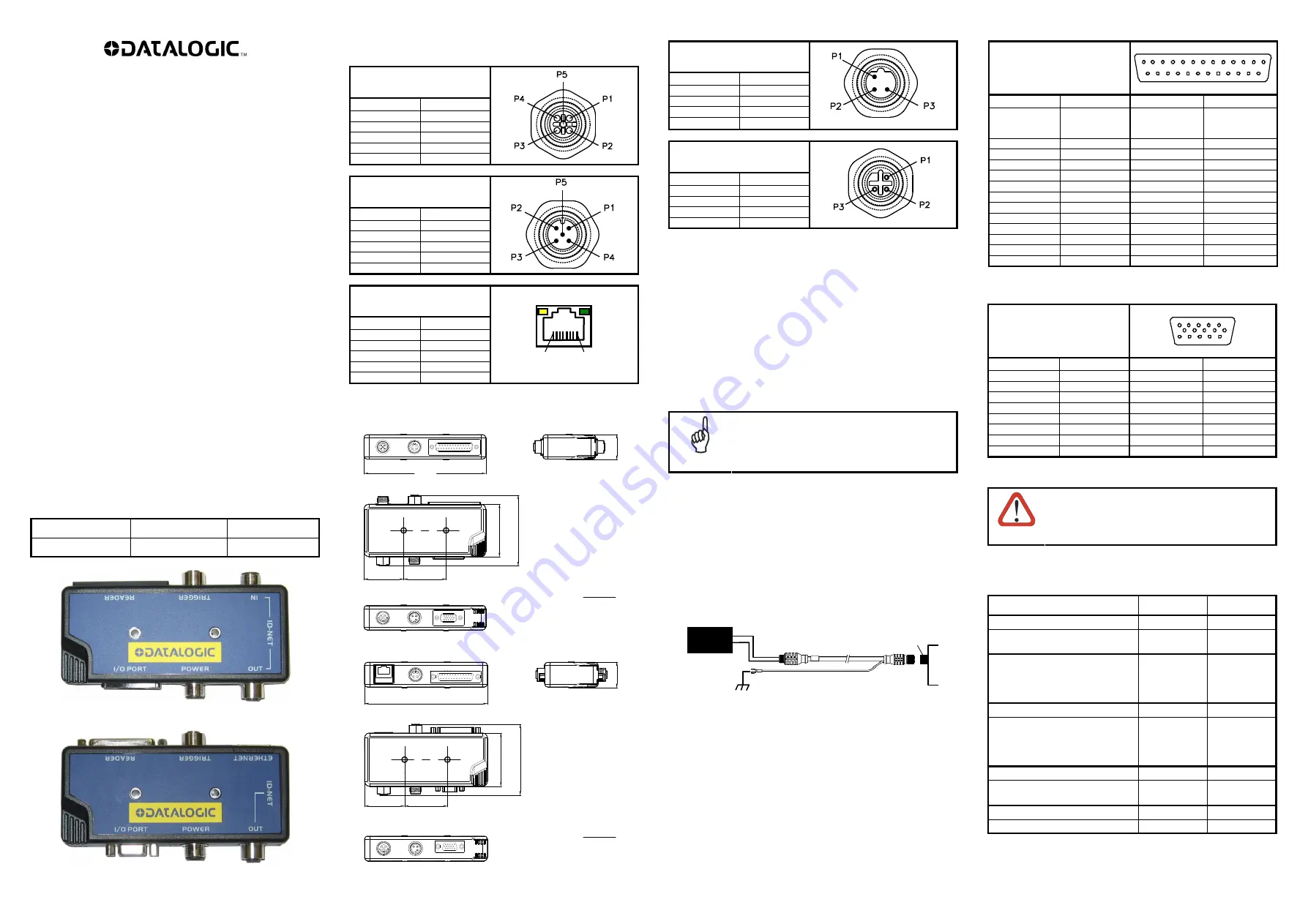
CONNECTIONS
ID-NET Out
M12 5P Female (A-coded)
Pin Function
1 Shield
2 Vdc
3 GND
4 ID+
5 ID-
QL300 only
(ID-NET In)
M12 5P Male (A-coded)
Pin Function
1 Shield
2 nc
3 GND
4 ID+
5 ID-
QL500 only
(Ethernet)
RJ45 8P Female
Pin Function
1 TX+
2 TX-
3 RX+
6 RX-
4, 5, 7, 8
nc
P8 P1
OVERALL DIMENSIONS
129
[4.56]
42
[1.49]
45
[1.59]
56
[1.98]
76
[2.67]
27
[0.95]
QL300
129
[4.56]
56
[1
.98]
42
[1.49]
45
[1.59]
27
[0.95]
76
[
2
.67]
QL500
Power
M12 3P Male (B-coded)
Pin Function
1 Earth
2 Vdc
3 GND
Trigger
M12 4P Female (A-coded)
Pin Function
1 +V
2 nc
3 -V
4 I1+
MOUNTING
There are two self-threading screws provided for mounting the
QLs to various wooden or plastic surfaces. Mounting to other
surfaces such as concrete walls or metallic panels requires user-
supplied parts (screws, screw anchors, nuts, etc). Keep in mind
that the connected reader must have its Chassis grounded to
Earth, see paragraph "Grounding".
QLs can also be mounted to a Bosch Frame using the BA200
mounting accessory.
The distance between mounting bushings is given in the overall
dimension diagram for each QL.
NOTE
IP65 protection is provided when the cables (or
QLs) are properly mated.
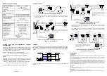
GROUNDING
There are two general rules to follow regarding network
grounding:
1) The network Shield must only be connected to Earth
ground at one point (the Master).
When using isolated power supplies, Earth grounding can be
accomplished through the CAB-PW-EXT accessory cable and
the BA400 or QL300/500 Power connector.
Power Supply
Earth ground connection
QL300
Power
CAB-PW-EXT
2) All reader Chassis must be connected to Earth ground.
All the readers in the network must have their
Chassis
connected to Earth ground
either by: mounting to
conductive metal brackets or frames which are connected to
Earth ground; or through the CBX or SC4000; or through the
QL bushing.
In the case of grounding through the CBX or SC4000, connect
the Earth signal to a good earth ground and set the internal
Chassis jumper to
Earth
.
In the case of grounding through the QL bushing, connect a
flying lead from the mounting bushing to an Earth ground. The
mounting bushing is internally connected to the reader
Chassis.
*
pins 4 and 5 are nc for QL500.
*
pins 4, 5, 12 and 15 are nc for QL500.
CAUTION
Do not connect GND and SGND to different (external)
ground references. GND and SGND are internally
connected through filtering circuitry which can be
permanently damaged if subjected to voltage drops over
0.8 Vdc.
ACCESSORIES
Description Part
Number
Connection
Cables
CAB-PW-EXT M12 POWER
EXTENSION CABLE
93A051381 Power
CBL-1480-01 THIN M12/5P
MALE/FEMALE 1M
CBL-1480-02 THIN M12/5P
MALE/FEMALE 2M
970101021
970101022
ID-NET Out/In
Terminators
CBL-1490 TERM. RESIST.
THIN M12/5P/MALE
970101069 ID-NET
Out
CBL-1496 TERM. RESIST.
THIN M12/5P/FEMALE
970101082 ID-NET
In
Field Mountable Connectors
FMC400 M12 3P F. CONN.
POWER
93ACC1884 Power
Mounting
BA200 Bosch Adaptors
93ACC1822
The FMC accessory connectors can be used to make custom
External Power and Service cables in case the standard cables
don't satisfy the application requirements.
Reader
25P D-Sub Female
1
14
25
13
Pin Function
Pin Function
1,
shell,
both bushings
Reader Chassis
2 TXM
14 nc
3 RXM
15 nc
4
RTSM
*
16 nc
5
CTSM
*
17 nc
6 I2A
18 I1A
7 GND
19 GND
8 O1+
20 RXA
9 nc
21 TXA
10 I2B
22 O1-
11 O2+
23 ID+
12 O2-
24 ID-
13 Vdc
25 GND
I/O Port
15P HD D-Sub Female
1
6
15
5
11
10
Pin Function
Pin Function
1 O1+
9 I2A
2 TXA
10 O2-
3 RXA
11 I2B
4
RXM
*
12
TXM
*
5
CTSM
*
13 GND
6 O1-
14 SGND
7 Vdc
15 RTSM
*
8 O2+
mm
in
mm
in


