background image

I


Maintenance Manual 


Summary of Contents for I-Class

Page 1: ...I Maintenance Manual...

Page 2: ...event will Licensor or its suppliers be liable for any damages or loss including direct incidental economic special or consequential damages arising out of the use or inability to use the Firmware So...

Page 3: ...i Contents 1 Overview 2 Adjustments and Maintenance 3 Troubleshooting 4 Removal and Replacement...

Page 4: ...ii...

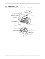
Page 5: ...i 1 Overview 1 0 Introduction 1 1 1 About the Printer 2...

Page 6: ...ii...

Page 7: ...at http www datamax oneil com For operating information reference the Operator s Manual part number 88 2241 01 For software information reference the Class Series 2 Programmer s Manual part number 88...

Page 8: ...ts the user assessable components of the printer Access Cover Printhead Media Sensor Ribbon Supply Hub Ribbon Take Up Hub Front Panel Printhead Assembly Fill Block Media Hub Internal Rewinder Printhea...

Page 9: ...2 2 2 Pressure Adjustment 9 2 2 3 Burn Line Adjustment 10 2 2 4 Voltage Adjustment 11 2 3 Ribbon Path Alignment 12 2 4 Maintenance 15 2 4 1 Cleaning the Printhead 16 2 4 1 1 Cotton Swab Procedure 16...

Page 10: ...21 2 5 1 Updating from READY 22 2 5 2 Updating from Download Mode 23 2 5 3 Resolving Update Issues 24 2 6 Boot Loader Program Updates 25 2 7 Resetting the Printer 26 2 7 1 Soft Reset 26 2 7 2 Level On...

Page 11: ...llow at least one label gap or mark to pass through the sensor Upon successful completion CALIBRATION COMPLETE will be displayed the printer will feed to the next label TOF and READY will be displayed...

Page 12: ...n Displayed Message Comment 1 Turn ON the printer UNCALIBRATED Wait briefly about six seconds for the printer to initialize 2 Press the Key and then raise the printhead assembly MENU MODE MEDIA SETTIN...

Page 13: ...f any under the sensor then press the key SCAN PAPER PRESS ESC KEY yyy If using preprinted media ensure that the sampled label area is free of preprinted text graphics or borders This sets the paper v...

Page 14: ...printer to initialize 2 Press the Key and then raise the printhead assembly MENU MODE MEDIA SETTINGS You are in MENU MODE 3 Press the Key MEDIA SETTINGS MEDIA TYPE You are in MEDIA SETTINGS 4 Press th...

Page 15: ...increment the Gain Number then press the Key and record the resulting Label Value Repeat this step for each of the remaining Gain Numbers 01 31 GAIN TRAN yyy 31 0 31 Or for reflective media GAIN REFL...

Page 16: ...h the values are above 20 subtract the Label Value from the corresponding TOF Value to find the Difference Value Note the Gain Number of the largest Difference Value GAIN TRAN yyy 31 0 31 Or for refle...

Page 17: ...e taken 15 Press the Key and then press the Key ADVANCED ENTRY SENSOR LEVELS The sensor readings must be entered into the printer 16 Press the Key Using the Key or the Key set the Paper Sensor Level t...

Page 18: ...ges and exit the menu Retest your media If unsuccessful repeat the procedure until a usable gain is obtained 2 2 Printhead Adjustments To ensure even and consistent print quality across a wide range o...

Page 19: ...uld only be performed however after attempting improvement using the HEAT and or PRINT SPEED settings Use only the minimum pressure needed following the steps below 1 Load 4 inch 102mm wide media and...

Page 20: ...Screws to of a turn 4 Turn the Adjustment Screws counter clockwise until the Burn Line is past the platen vertex Print a Validation Label from the Quick Test Menu The label should look light and unev...

Page 21: ...ing a multi meter set to measure DC voltage connect the positive lead to Power Supply Connector J2 pin 1 and the negative lead to J2 pin 6 3 Raise the Printhead Assembly Locate and note the Printhead...

Page 22: ...0 1100 23 8 1101 1141 24 2 1142 1183 24 7 1184 1224 25 1 I4406 1225 1265 25 5 1530 1598 22 4 1599 1665 22 9 1666 1733 23 4 1734 1800 23 8 1801 1868 24 2 1869 1935 24 7 1936 2003 25 1 I4604 2004 2070 2...

Page 23: ...racking If lateral movement is excessive this must be corrected before proceeding typical causes include an unlatched printhead uneven printhead pressure a worn platen or worn platen bearings 5 Observ...

Page 24: ...of ribbon wrinkling proceed to Step 8 otherwise slightly loosen the Ribbon Shield Adjustment Screws Move the Ribbon Shield forward or backward to smooth the ribbon Tighten the Ribbon Shield Adjustment...

Page 25: ...leaning Interval Method Supplies Printhead Media type dependent Thermal transfer after each roll of ribbon Direct thermal after each roll of media or as needed Isopropyl alcohol and if necessary Print...

Page 26: ...rials are recommended for cleaning the printhead as detailed below Faulty Label Streaks e g white lines in the direction of print can indicate a dirty or faulty printhead 2 4 1 1 Cotton Swab Procedure...

Page 27: ...Section 2 4 1 1 1 Turn OFF and unplug the printer Wait for the printhead to cool 2 Raise the Printhead Assembly then remove the media and ribbon if installed 3 Place a Cleaning Card part number 70 20...

Page 28: ...s As an alternate CLEAN HEAD NOW can be selected in the menu 7 Turn OFF and unplug the printer Clean the printhead see Section 2 4 1 1 8 Install media and ribbon if necessary Lower and latch the Print...

Page 29: ...other contaminants accumulate inside the printer the particles can be pulled through the Media Sensor to the printhead causing inconsistent label detection and voids in the print To prevent problems c...

Page 30: ...tracking 2 4 4 Cleaning the Ribbon Path If equipped with the Thermal Transfer option as ink accumulates on the Ribbon Path components smooth ribbon flow can be impeded causing wrinkling To prevent pr...

Page 31: ...S SERIAL PORT A BAUD RATE 9600 BPS PROTOCOL BOTH PARITY NONE DATA BITS 8 STOP BITS 1 SERIAL PORT B NOT INSTALLED SERIAL PORT C NOT INSTALLED SERIAL PORT D NOT INSTALLED USB PORT NOT INSTALLED SYSTEM I...

Page 32: ...me lpt1 As an example this would be entered as copy i4212_1105 zg lpt1 Where lpt1 can differ to include another port as equipped The Ready Indicator will flash as data is received 2 UPGRADING SOFTWARE...

Page 33: ...r see Section 2 5 1 for an example The printer is ready to accept the new application version Note The parallel port LPT1 must be used to write to the printer 3 UPDATE SOFTWARE READING IMAGE No action...

Page 34: ...nues the Main Logic PCB may be defective see Section 4 11 ERROR WRITING FLASH The program could not be written into the Flash memory a possible Flash memory defect try the download again however if th...

Page 35: ...ersion Note Boot Loader program updates can only be performed when Application Version 2 09 or greater is running in the printer Boot Loader Update Procedure Step Displayed Message Operator Action Com...

Page 36: ...and hold the PAUSE and CANCEL Keys while turning ON the printer then continue to depress the keys until the SYSTEM RESET message flashes Note This reset has the same effect as the SYSTEM SETTINGS SET...

Page 37: ...1 Initial Steps 1 3 2 General Problem Resolution 1 3 2 1 Problem Isolation 2 3 2 2 No Power 3 3 2 3 No Print 4 3 2 4 Poor Print Quality 5 3 2 5 Communications Problems 6 3 3 Error Resolution 7 3 3 1 W...

Page 38: ...ii...

Page 39: ...ensure that the unit has been placed on a level stable surface and 3 use extreme care if measuring voltages Perform the following actions before troubleshooting then proceed according to the symptom...

Page 40: ...as a Print Quality Label produced Go to Step 3 3 Was a fault message generated Go to Section 3 3 2 Go to Section 3 2 3 4 Examine the label Is the print quality satisfactory Go to Step 5 Go to Section...

Page 41: ...Section 4 2 1 2 Turn OFF and unplug the printer Check fuses F1 and F2 on the Power Supply PCB Is a fuse blown Replace the fuse s see Section 4 9 If the fuse s continue s to fail replace the Power Sup...

Page 42: ...f using thermal transfer media examine the used ribbon and then proceed accordingly The used ribbon has an image Possible incorrectly loaded ribbon reload correctly Possible wrong ribbon type CSO CSI...

Page 43: ...Section 2 4 1 2 2 3 or 4 4 respectively Possible loose or defective printhead cable Possible ribbon wrinkle see Section 2 3 Possible defective Main Logic PCB replace it see Section 4 11 Possible dirt...

Page 44: ...p Mode disable it see Section 3 4 3 Press TEST Scroll to PRINT CONFIGURATION and then press TEST Compare the communications settings listed on the Configuration Label to the host s communication setti...

Page 45: ...LERANCE A drop in the 24 VDC supply has been detected Cycle the power OFF and ON If the message appears try the following WARNING Use extreme caution when measuring voltages 1 Move the printer to anot...

Page 46: ...NG The host has changed the printer s configuration but the changes have not taken effect To save these changes send a host reset command in DPL or to discard the changes perform a soft reset see Sect...

Page 47: ...on 4 11 CUTTER FAULT A blade positioning fault has occurred 1 Try cycling printer power OFF and ON 2 Ensure the media being cut is within specification WARNING Turn OFF and unplug the printer before e...

Page 48: ...ective replace it see Section 4 7 4 The Main Logic PCB may be defective replace it see Section 4 11 GAP MODE FAULTY SENSOR Consistently high sensor readings have been recorded Press any key to continu...

Page 49: ...ithin the print logic has been detected Try cycling the power OFF and ON If the problem persists possible defective Main Logic PCB replace it see Section 4 11 RAM FAULT RAM error has occurred Try cycl...

Page 50: ...e Ribbon Supply Ensure that ribbon is correctly installed that the Printhead is latched that the Leveling Cam is adjusted and that the printer is calibrated see the Operator s Manual If the problem pe...

Page 51: ...EED increase the bar code height or adjust the MIN READABLE HEIGHT or the REDUNDANCY LEVEL 7 Align the scanner 8 Ambient light maybe interfering with the optics Reduce bright light sources alternately...

Page 52: ...etected within the maximum label length setting or a TOF was unexpectedly detected Note When the SENSOR TYPE is REFLECTIVE this fault is given for an out of stock condition Press the FEED Key then pro...

Page 53: ...ULT A bar code could not successfully be verified Note This is a normal condition if a bar code is not verifiable Simultaneously press the Verifier s ENTER and F1 Keys to clear If the fault continues...

Page 54: ...bon if thermal transfer printing then proceed according to the type Turn ON the printer Enter DIAGNOSTICS and enable HEX DUMP MODE Exit the menu and save the changes Note To exit Hex Dump Mode enter D...

Page 55: ...4 4 1 1 Head Pressure Cams and Springs 11 4 5 Thermal Transfer Assembly 13 4 5 1 Ribbon Supply Hub 15 4 5 2 Ribbon Take up Hub Clutch Assembly 16 4 6 Rewind Assembly 17 4 6 1 Rewind Hub Clutch Assembl...

Page 56: ...ii 4 11 Main Logic PCB 27 4 12 Backplane PCB 29...

Page 57: ...TION Always disconnect AC power before performing service Wear a wrist strap and follow all ESD prevention measures and Use extreme care and never use sharp objects on the Printhead or Platen Note The...

Page 58: ...eplate Replacement 1 Lower the Cover Assembly onto the printer 2 Reinstall the two Screws through the Cover Assembly and into the Baseplate 3 Tighten the two Screws along the Baseplate and the two Scr...

Page 59: ...el from the Baseplate Notch as Tab access is limited Front Panel Tabs Centerplate Replacement 1 Align the Tabs of the Front Panel to the Centerplate Notches and the Baseplate Notch 2 Press firmly unti...

Page 60: ...the Front Panel PCB to the Centerplate then disconnect the Front Panel Cable and remove the Front Panel PCB Centerplate Bezel Button Panel Screws Front Panel PCB Bezel Tabs Replacement 1 Connect the F...

Page 61: ...ck Thumbscrew Tear Bar Platen Block Fascia Printhead Assembly 4 Remove the Sensor Cover or if equipped the Present Sensor pulling the far side out then away from the Centerplate If Present Sensor equi...

Page 62: ...Platen Block ensuring proper gear mesh 2 Position the Bearing Plate onto the Platen Block and secure it with the two Screws Rotate the Platen Assembly to verify gear mesh 3 Position and then snap the...

Page 63: ...al 1 Turn OFF and unplug the printer 2 Raise the cover With the Printhead Assembly lowered loosen the Printhead Mounting Screw it will remain in the assembly Printhead Mounting Screw Printhead Assembl...

Page 64: ...thead Assembly Locating Pins 3 Secure the Printhead to the Printhead Assembly with the Printhead Mounting Screw but do NOT over tighten 4 Clean the Printhead see Section 2 5 1 5 Lower and latch the Pr...

Page 65: ...n Idler Centerplate Printhead Assembly End Cap Screws Ribbon Idler Head Lift Spring Wavy Washer Extrusion 5 Remove the Printhead Assembly and the Head Lift Spring Replacement 1 Place the Head Lift Spr...

Page 66: ...mbly Boss Wavy Washer 4 Insert the Ribbon Idler shaft into the Centerplate bushing 5 Reinstall the End Cap onto the Extrusion to captivate the Printhead Assembly Boss and Ribbon Idler shaft then secur...

Page 67: ...ion 4 4 1 2 Carefully pry the Clip from the Printhead Assembly Also remove the two Screws that secure the Ribbon Shield and then remove it from the Printhead Assembly Printhead Assembly Ribbon Shield...

Page 68: ...g the spring loaded assembly as necessary to separate the parts and then remove the Alignment Springs Printhead Assembly Lower Carriage Alignment Springs 5 Separate the Middle Carriage from the Upper...

Page 69: ...but do not tighten the Upper Middle and Lower Carriages with the Alignment Screws and the Locking Screws 4 Reinstall the Clip and secure the Ribbon Shield to the Printhead Assembly with the two Screws...

Page 70: ...crews Replacement 1 Inspect and if necessary wipe the Light Pipe clean using isopropyl alcohol and lens tissue or lint free cloth Light Pipe 2 Reinstall the Thermal Transfer Assembly in the Centerplat...

Page 71: ...secures the Ribbon Supply Hub to the Housing 3 Remove the Ribbon Supply Hub and Nylon Washer from the Housing Ribbon Supply Hub Nylon Washer Metal Washer Screw Housing Replacement 1 Place the Nylon Wa...

Page 72: ...nd Screw 5 Reinstall the Thermal Transfer Assembly see Section 4 5 4 5 2 Ribbon Take up Hub Clutch Assembly Removal 1 Remove the Thermal Transfer Assembly see Section 4 5 2 Remove the E Ring from the...

Page 73: ...ub shaft through the Take Up Hub Clutch and Thermal Transfer Housing 4 Reinstall the Inner Bearing and clip the E Ring onto the Take Up Hub shaft 5 Reinstall the Thermal Transfer Assembly see Section...

Page 74: ...bly in the Centerplate carefully engaging the gears and secure it using the three Screws 4 6 1 Rewind Hub Clutch Assembly and Spur Gear Removal 1 Remove the Rewind Hub Assembly see Section 4 6 2 Remov...

Page 75: ...ing 3 Slide the Rewind Hub shaft through the Rewind Hub Clutch and Rewind Housing 4 Reinstall the Inner Bearing and clip the E Ring onto the Rewind Hub shaft also if removed position the Spur Gear ont...

Page 76: ...4 20 Media Idler 4 Pull the Media Sensor Guide and then the Media Sensor from the printer Replacement 1 Reinstall the Media Sensor and then the Media Sensor Guide 2 Secure the Media Sensor Guide to t...

Page 77: ...4 8 Drive Motor Assembly Proceed with removal and replacement of the Drive Motor Assembly depending upon the type 4 8 1 Belt Drive Removal 1 Turn OFF and unplug the printer 2 Remove the Cover Assembly...

Page 78: ...otor Pulley and the Motor Mounting Block Gear engaging the teeth then reinstall and tighten the four Screws 2 Position the Drive Assembly onto the Centerplate Standoffs and then secure the assembly wi...

Page 79: ...Cable Lug and then remove the Drive Motor Isolator Drive Motor Screws Ground Cable Lug Replacement 1 Position the Drive Motor against the Isolator 2 Place the Ground Cable Lug onto one Screw then sec...

Page 80: ...Screws that secure the Isolator to the Centerplate Standoffs Screws Isolator Centerplate Standoffs 203 400 DPI Screws Isolator Centerplate Standoffs 300 600 DPI Replacement 1 Depending upon the resolu...

Page 81: ...re in the primary switching circuit and may indicate a more serious electrical problem Removal 1 Turn OFF and unplug the printer 2 Remove the Cover Assembly see Section 4 1 3 Remove Fuses F1 and or F2...

Page 82: ...e cables from the Power Supply PCB 4 Remove the two Screws and Nut Plate that secure the AC Connector Screws Nut Plate AC Connector 5 Remove the Screw and Washer that secures the Ground Wire Lug to th...

Page 83: ...to the chassis with the Screw 3 Position the Nut Plate over the AC Connector and then secure the AC Connector and the Nut Plate to the chassis with the two Screws 4 Reconnect the cables to the Power S...

Page 84: ...Card Cage Guides Filler Plate 4 Pull the Main Logic PCB from the Card Cage Replacement 1 If replacing Main Logic PCB P N 51 2301 01 ensure that the Jumper is placed between E1 E2 also see note below...

Page 85: ...on Version for the printer model see Section 2 6 6 Configure the printer see the Operator s Manual for details 7 Perform calibration see Section 2 1 4 12 Backplane PCB Removal 1 Turn OFF and unplug th...

Page 86: ...s that secure the Backplane PCB to the Card Cage and then remove the Backplane PCB Backplane PCB Card Cage Screws Replacement Proceed according to the Part Number of the Backplane PCB If installing P...

Page 87: ...according to the equipped options and default requirements Scanner equipped E1 E2 E5 E6 RFID equipped E2 E3 E4 E4 COM2 DTR Active default E7 E8 and Ribbon Motion default E11 E12 2 Place the Backplane...

Page 88: ...of the Backplane PCB P N 51 2311 00 P N 51 2348 00 4 Replace the Main Logic PCB and the Filler Plate see Section 4 11 Also replace any optional PCB removed from in the Card Cage 5 Replace the Cover A...

Reviews: