

Reviews:
No comments
Related manuals for VSN900X

1404150
Brand: Global American Pages: 14

Hotwire 8747
Brand: Paradyne Pages: 11

Hotwire 8820 GranDSLAM Series
Brand: Paradyne Pages: 60

SC510T-200B
Brand: Supero Pages: 48

cDAQ-9174
Brand: National Instruments Pages: 4

NI PXIe-1078
Brand: National Instruments Pages: 41
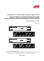
NJR-RW01UHD
Brand: IDK Pages: 44

FlexATX Chassis
Brand: NEC Pages: 8

PXIe-1092
Brand: National Instruments Pages: 7

9146
Brand: National Instruments Pages: 22

RC21-01400
Brand: Razer Pages: 9

CRS-1 - Carrier Routing System Router
Brand: Cisco Pages: 104


