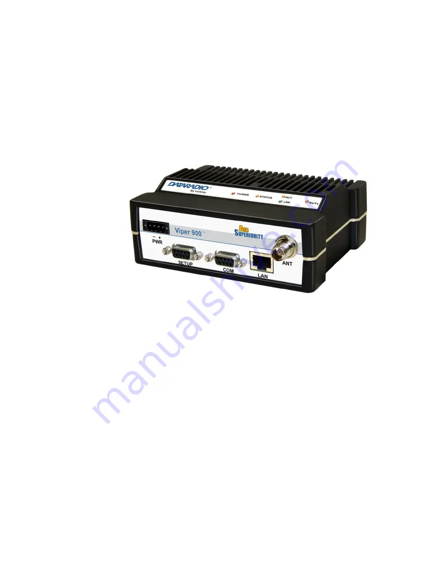
Dataradio 140-5018-500, User Manual
The Dataradio 140-5018-500 is a top-of-the-line communication device designed for professionals in need of reliable data transmission. Unlock the full potential of this cutting-edge technology by accessing the comprehensive User Manual, available for free download exclusively at 88.208.23.73:8080. Get the most out of your Dataradio experience with this essential manual.
Share
Download


Reviews:
No comments
Related manuals for 140-5018-500
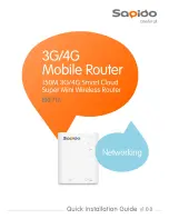
BRB72n
Brand: Sapido Pages: 101
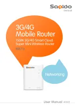
BRB72n
Brand: Sapido Pages: 21
GW7304-3G-AC
Brand: virtual access Pages: 336
X8 AC1750
Brand: Sitecom Pages: 10
GW2021
Brand: virtual access Pages: 423
F7B30
Brand: Four-Faith Pages: 81
f7946 series
Brand: Four-Faith Pages: 82
KW6516
Brand: Kasda Pages: 29
Viper-1000
Brand: Dataradio Pages: 113
DIR-501
Brand: D-Link Pages: 98
DIR-501
Brand: D-Link Pages: 60
DIR-612
Brand: D-Link Pages: 78
WN-200R
Brand: Air Live Pages: 124
DIR-612
Brand: D-Link Pages: 12
Archer C50(EU)3.0
Brand: TP-Link Pages: 83
BRE71n
Brand: Sapido Pages: 21
BRE71n
Brand: Sapido Pages: 101
mAP lite
Brand: MikroTik Pages: 4


