background image


HD/SD Recorder 


HDR-55 


Quick Start Guide 


www.datavideo-tek.com


Summary of Contents for HDR-55

Page 1: ...HD SD Recorder HDR 55 Quick Start Guide www datavideo tek com ...

Page 2: ...11 Connecting to a PC MAC 11 HD MPEG2 BIT RATE Menu 12 SD MPEG2 BIT RATE Menu 13 SET 1080i H RES Menu 14 GPI Mode Functions Menus 15 Select the GPI Function 15 Set Date Time Menu 16 Format Hard Disk Menu 17 Erase Track Menu 17 HDD Surface Scan Menu 18 Playing a Track 19 Recording a track 20 Connecting to a Computer 21 Connecting to a PC 21 Connecting to a MAC 23 RS 422 Protocol Reference V1 0 24 D...

Page 3: ... cord do not exceed the extension cord s rating 10 Make sure that the total amperes of all the units that are plugged into a single wall outlet do not exceed 15 amperes 11 Never push objects of any kind into this unit through the cabinet ventilation slots as they may touch dangerous voltage points or short out parts that could result in risk of fire or electric shock Never spill liquid of any kind...

Page 4: ...manner other than that specified by Datavideo or has been subjected to abuse or modification will be repaired for time and material charges at the Buyer s expense This warranty does not affect your statutory rights within the Country of purchase Disposal For EU Customers only WEEE Marking This symbol on the product indicates that it will not be treated as household waste It must be handed over to ...

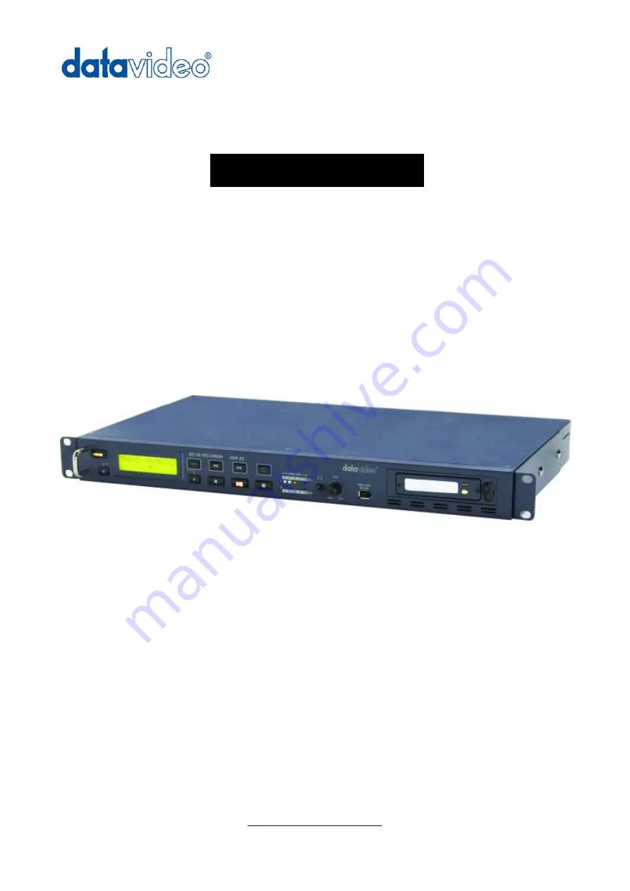
Page 5: ...ith a choice if IBP or Intra frame i frame The recorded files are compatible with a wide range of NLE and play out solutions The compatible 2U design can be easily integrated with other equipment or can be used as a stand alone recorder player in the studio or on location Features HD SDI SD SDI video input with loop though HDMI output and SDI output Video record format SD 5Mbps 15Mbps IBS 4 2 0 co...

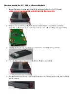
Page 6: ...e PCB board and slide the drive towards the rear SATA connectors on the board Turn the PCB over and secure it with four Philips screws included 3 Slide the PCB board into the enclosure with the SATA connectors facing outward 4 Close the back cover and secure it with the two Philips screws black 5 Push the hard drive enclosure into the hard drive slot of the recorder and turn the latch to the left ...

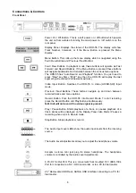
Page 7: ...put Button Switches the HDR 55 to Video HD SD SDI Input mode Previous Next Buttons These buttons navigate up and down between recorded tracks and menu options Record Button Puts the HDR 55 into Record Mode To start recording press the Record Button and Play Button simultaneously N B Unit will not record if no video signal is present Play Pause Button Starts playback of a track or pauses playback o...

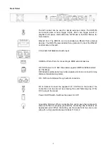
Page 8: ...tput 4 2 2 SDI Video data supports SMPTE 292M standard at 1 5G Mbps SDI transfers professional level video signals and it s can connect to long distance transmission systems HD SDI input and pass through output connectors DC In Socket Connect the supplied 12V 3A PSU to this socket The connection can be secured by screwing the outer fastening ring of the DC In plug to the socket Power On Off Switch...

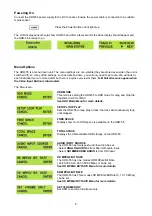
Page 9: ...Menus are HDD MODE This mode is setting the HDR 55 to HDD mode for drag and drop file transfers to a PC or MAC See HDD Mode Menu for more details SETUP LOOP PLAY Sets the HDR 55 to loop play a track the track will continuously loop until stopped FREE SPACE Displays how much HDD space is available on the HDR 55 TOTAL SPACE Displays the total available HDD storage on the HDR 55 AUDIO INPUT SOURCE Th...

Page 10: ...RD DISK Formats the HDD and removes all files and tracks from the HDR 55 See Format Hard Disk Menu for more details ERASE TRACK Erases individual tracks from the HDR 55 See Erase Track Menu for more details HDD SURFACE SCAN Checks the HDD for errors bad sectors This is only necessary if your HDR 55 is not performing correctly or you install a new HDD A result txt file is created in the root direct...

Page 11: ...ode Select RS 232 mode you can control HDR 55 via RS 232 from PC Select RS 422 mode you can control HDR 55 via RS 422 from external devices UPDATE FP FIRMWARE When this mode set enable HDR 55 will into the BOOT Loader mode for upgrade FP firmware FIRMWARE VERSION Display the Rev No and Firmware Version of the HDR 55 ...

Page 12: ...aying back the track The HDR 55 uses a FAT32 file structure so large tracks are broken down into 2 GB files which are sequentially named For example if Track 02 is 1 hour in duration it will appear as follows hdv02 m2t 2 GB hdv02 is the file name for Track 02 hdv02_01 m2t 2 GB Each 2 GB section is given a sequential _xx numeric extension hdv02_02 m2t 2 GB hdv02_03 m2t 2 GB hdv02_04 m2t 2 GB hdv02_...

Page 13: ...MPEG2 BIT RATE menu Use the FWD or REW Button to select the desire bit rates 20 25 30 35 40 45 50 55 60 To confirm your selection and exit the menu press the Next Button right Then press the Menu Button to leave menu mode For example the table of 120 GB HDD is the reference of Bit Rate mode selection HDD Type Bit Rate Mode Maximum Recordable Time 120GB 20 Mbps 810 minutes 760 120GB 40 Mbps 405 min...

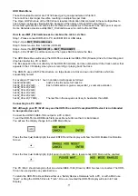
Page 14: ...the FWD Button to navigate the menus until SD MPEG2 BIT RATE is displayed Press the Next Button right to enter the SD MPEG2 BIT RATE menu Use the FWD or REW Button to select the desire bit rates 5 10 15 To confirm your selection and exit the menu press the Next Button right Then press the Menu Button to leave menu mode ...

Page 15: ...selection and exit the menu press the Next Button right Then press the Menu Button to leave menu mode 1080i is the shorthand name of a format of high definition video modes 1080 is number of horizontal scan lines and the letter i stands for interlaced 1080i is a high definition television HDTV video mode The term usually assumes a widescreen aspect ratio of 16 9 implying a horizontal resolution of...

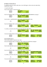
Page 16: ...FWD Button to select either Pulse Trigger or Level Trigger To confirm your selection and exit the menu press the Next Button right Then press the Menu Button to leave menu mode Select the GPI Function Press the Menu Button to enter the menu mode Press the FWD Button to navigate the menus until SET GPI FUNCTION is displayed Press the Next Button right to enter the SET GPI FUNCTION menu Press the FW...

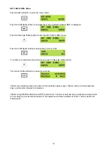
Page 17: ... value To set the date use the Play Pause Button to increase the value or the Stop Button to decrease the value Increases Value Decreases Value Use the FWD Button to move the cursor to the next column to the right i e Month Year Hours Minutes or the REW Button to move the cursor back to the left Moves the cursor to the right Moves the cursor to the left Once you have set the date time press the Ne...

Page 18: ... disk After a few seconds the HDR 55 will reboot and the display will return to normal Erase Track Menu Erase Track is used for deleting individual tracks from the HDR 55 Press the Menu Button to enter menu mode Press the REW Button to navigate the menus until ERASE TRACK is displayed Press the Next Button right to enter the ERASE TRACK menu Use the FWD or REW Button to select the track that you w...

Page 19: ...o enter menu mode Press the REW Button to navigate the menus until SCAN HDD SURFACE is displayed Press the Next Button right twice to start the HDD Surface Scan The progress of the scan will appear in the LCD display Once complete the Surface Scan Done message will appear Press the Next Button right to exit the surface scan A txt file called Result will have been created in the root directory of t...

Page 20: ...set up loop play press the Menu Button to enter menu mode and then the FWD Button until SETUP LOOP PLAY is displayed Press the Next Button right to enter the setup loop play menu and then press the FWD Button to select ENABLE Press the Next Button right to select SET and then press the Menu Button to return to track display When you press play the selected track will start playing and will loop un...

Page 21: ...nt The Video Input Button is illuminated The track you have selected on the HDR 55 is empty The counter next to the TrackNo on the LCD display should b showing 00 00 00 00 There is some available space on the HDR 55 Hard Disk Go to the FREE SPACE Menu and check that the HDR 55 is not full During record you can pause the HDR 55 by pressing the Play Pause button the counter on the LCD display will s...

Page 22: ...ension hdv02_02 m2t 2 GB hdv02_03 m2t 2 GB hdv02_04 m2t 2 GB hdv02_05 m2t 2 GB hdv02_06 m2t 77 MB The last file in the sequence is likely to be smaller than 2GB Once transferred to a PC MAC files can be dropped onto a timeline in a suitable NLE application and they will playback seamlessly Connecting to a PC NB Although a PC may see the HDR 55 as an AVC compliant DV Device it is not intended to be...

Page 23: ...the HDR 55 to Deck Mode use Safely Remove Hardware You will find Safely Remove Hardware on the Taskbar Double click on Safely Remove Hardware and the dialog box will appear select the Datavideo HDD IEEE SBP2 Device and click on Stop A second dialog box will appear Select Datavideo HDD IEEE SBP2 Device and click on OK After a few seconds a Safe To Remove Hardware message should appear above the Tas...

Page 24: ... Button right to select ENTER and the display will show the HDD Enable Confirmation Screen Press the Next Button right again to confirm after a few seconds HDD Mode will be enabled The MAC should see the HDR 55 as a HDD and the files will appear in the root directory of the drive You can select the required files and drag and drop them to the required destination To un mount the HDR 55 from your M...

Page 25: ...rial word serial with data exchange between devices 4 Standard transmission rate on the interface bus is 38400 bits per seconds bps 5 The data word utilized by the interface system is as follows 6 1 Start bit 8 Data bits 1 Parity bit 1 Stop bit Odd Parity ODD parity The total of 1 s in D0 D1 D7 PARITY equals an odd number D0 D1 D2 D3 D4 D5 D6 D7 PARITY ODD START BIT STOP BIT ...

Page 26: ...ls the lower Least Significant nibble It CMD 1 indicates the command or return group to which the command belongs as per the table below CMD 1 Function Initiator 0x System Control Controller 1x System Control Return Device HDR 45 55 2x Transport Control Controller 4x Preset And Select Control Controller 6x Sense Request Controller 7x Sense Return Device HDR 45 55 Ex DVR Control Controller Fx DVR R...

Page 27: ...eceive A RX Transmit A TX 3 Transmit B TX Receive B RX 4 Transmit Common Receive Common 5 Spare Spare 6 Receive Common Transmit Common 7 Receive B RX Transmit B TX 8 Transmit A TX Receive A RX 9 Frame Ground Frame Ground The RS 232 pin assignment of the Controller and HDR 45 55 is shown in the following table Signal Pin Controller HDR 45 55 1 2 Receive RX Transmit TX 3 Transmit TX Receive RX 4 5 G...

Page 28: ...cts an interruption of a byte in a COMMAND block that exceeds 10 milliseconds it executes a TIME OUT error sequence voids the receiving COMMAND block and transmit a NAK TIME OUT When a DEVICE HDR 45 55 receives a COMMAND block from the CONTROLLER the DEVICE must transmit a response within 9 milliseconds Therefore if the CONTROLLER cannot receive the appropriate response from the DEVICE within 10 m...

Page 29: ...mode 10h 01h ACK 41h 52h nnh mmh Select Track Track 01 99 10h 01h ACK 42h 52h nnh mmh Select Track Track 001 999 10h 01h ACK 41h 53h nnh Select Video Input Source 10h 01h ACK 41h 61h nnh Select Audio Input Source 10h 01h ACK 61h 0Ch 01h Current Time Sense 74h 04h Current Time 61h 20h Status Sense 7xh 20h Current Status E0h 01h Get Length of Current Track F4h 01h Length of Track E0h 02h Current Vid...

Page 30: ... 40h 51h 91h Return 10h 01h 11h 40h 54h DELETE CURRENT TRACK Send 40h 54h 94h Return 10h 01h 11h 40h 62h ENABLE HDD MODE Send 40h 62h A2h Return 10h 01h 11h 41h 52h NNh SELECT TRACK NUMBER Track 01 99 NN Track Number Send 41h 52h 01h 94h Select Track 1 Return 10h 01h 11h Send 41h 52h 10h A3h Select Track 16 Return 10h 01h 11h 42h 52h NNh MMh SELECT TRACK NUMBER Track 001 999 NN Track Number Hex 10...

Page 31: ...eturn 71h 20h 99h 2Ah Current track number is 99 E0h 01h TRACK LENGTH SENSE Send E0h 01h E1h Return F4h 01h 29h 41h 56h 00h B5h Track Length 00 56 41 29 E0h 02h CURRENT VIDEO SOURCE SENSE 1 SDI 2 Decode MPEG 2 Send E0h 02h E2h Return F1h 02h 01h F4h SDI Input Send E0H 02h E2h Return F1h 02h 02h F5h Decode MPEG 2 E0h 03h CURRENT AUDIO SOURCE SENSE 0 Analog audio 1 SDI Embedded Audio Send E0h 03h E3...

Page 32: ...h 01h Length of Current Track BCD Bit 7 Bit 6 Bit 5 Bit 4 Bit 3 Bit 2 Bit 1 Bit 0 Data 0 0 0 Tens of Frames Frames Data 1 0 Tens of Seconds Seconds Data 2 0 Tens of Minutes Minutes Data 3 0 0 Tens of Hours Hours Send E0h 01h E1h Return F4h 01h 29h 41h 56h 00h B5h Track Length 00 56 41 29 F1h 04h Current Track Number BCD Track 01 99 Bit 7 Bit 6 Bit 5 Bit 4 Bit 3 Bit 2 Bit 1 Bit 0 Data 0 Tens of Tra...

Page 33: ...ck Number BCD 0 9 Data 10 Data 13 Data 14 SDI Embedded Analogue Audio Decode MPEG 2 Encode SDI Data 15 Data 0 BIT 0 LOCAL This bit will be set to 1 when the device will only accept commands from the front panel and not the controller RS 232 422 BIT 2 HARDWARE ERROR This bit will set to 1 when a hardware error occurs in the device BIT 5 DISK OUT The removable media is not present in the device BIT ...

Page 34: ...will be set to 1 when the device is searching backwards BIT 5 LAMP FORWARD This bit will be set to 1 when the device is searching forwards BIT 6 LAMP STILL This bit will be set to 1 when the device has finished searching Data 8 BIT 0 TRACK IS NOT EMPTY REC INHIBIT If this bit is set to 1 record command will be ignored it is not an empty track BIT 4 DISK FULL Set to 1 if the device has reached the ...

Page 35: ...ding SDI source BIT 2 DECODE MPEG 2 This bit will be set to 1 if the device is decoding MPEG 2 BIT 4 ANALOGUE AUDIO This bit will be set to 1 if the audio input source is analogue BIT 5 SDI EMBEDDED This bit will be set to 1 if the audio input source is SDI embedded audio Revision History Rev Description Date FP Rev MB Rev 1 0 1 Initial release V1 0 0 V1 5 0 ...

Page 36: ...35 Dimension ...

Page 37: ...put return loss More than 15 dB 5MHz to 750MHz More than 10 dB 750MHz to 1 5 GHz Output level 0 8 Vpp 10 Rise time Less than 270 ps Fall time Less than 270 ps Difference between rise time and fall time within 100 ps Alignment jitter Less than 0 2 UI Timing jitter Less than 1 0 UI Eye aperture ratio More than 90 DC offset 0 0 5V Equalizer use 5C FB cable support 100 meters SD SDI signal SMPTE 259M ...

Page 38: ...ited Tel 44 1457 851 000 Fax 44 1457 850 964 E Mail sales datavideo co uk Datavideo Technologies Co Ltd Tel 886 2 8227 2888 Fax 886 2 8227 2777 E mail service datavideo com tw Datavideo Technologies China Co Ltd Tel 86 21 5603 6599 Fax 86 21 5603 6770 E mail service datavideo cn Datavideo Technologies S PTE LTD Tel 65 6749 6866 Fax 65 6749 3266 E mail service datavideo sg Datavideo HK Limited Tel ...

Reviews: