background image


Aestiva/5


Operation Manual - Part 1


Software Revision 4.X


System Controls, Operation, Checkout

Summary of Contents for Aestiva/5

Page 1: ...Aestiva 5 Operation Manual Part 1 Software Revision 4 X System Controls Operation Checkout...

Page 2: ...uct must not be altered without the prior written approval of Datex Ohmeda The user of this Product shall have the sole responsibility for any malfunction which results from improper use faulty mainte...

Page 3: ...1 How to set controls 2 14 How to use the menu 2 15 Menu map 2 16 More about menu functions 2 17 How to change menu settings 2 18 Optional flowmeter and suction regulators 2 19 Suction regulator contr...

Page 4: ...3 26 Reading the pressure waveform Paw 3 27 Scales 3 27 Measure circuit compliance 3 30 Show the service settings 3 31 Optional Passive AGSS operation 3 33 Optional Active AGSS operation 3 34 Connecti...

Page 5: ...back pressure test A 8 Power failure test A 9 Precase steps A 11 Every time a different clinician uses the system A 12 Low pressure leak test A 12 Before every patient A 16 Inspect the system A 16 Mi...

Page 6: ...Aestiva iv 1006 0938 000 iv...

Page 7: ...1006 0938 000 1 1 1 Introduction 1 1 In this section How to use this manual 1 2 What is an Aestiva 1 2 Symbols used in the manual or on the equipment 1 5...

Page 8: ...stems equipped with these functions Use this manual together with Part 2 which includes setup troubleshooting calibration and maintenance procedures What is an Aestiva The Aestiva is a flexible access...

Page 9: ...e system uses a microprocessor controlled ventilator with internal monitors electronic PEEP multiple modes of ventilation and a pressure waveform dis play Built in connectors and communication softwar...

Page 10: ...c display mount Two vaporizer positions left hand configuration with arm display mount Three vaporizer positions left hand configuration with arm display mount Three vaporizer positions right hand con...

Page 11: ...replace words on the equipment or in Datex Ohmeda manuals No one device or manual uses all of the symbols These symbols include l On power Not autoclavable O Off power m Type B equipment o Standby Ty...

Page 12: ...tion and Maintenance Manuals The xxxx is the certification number of the Notified Body used by Datex Ohmeda s Quality Systems t Variability Read top of float T Variability in steps Vacuum inlet Plus p...

Page 13: ...ion r Mechanical ventilation u Open drain remove liquid U Close drain q Inspiratory flow Q Expiratory flow t O2 sensor connection End case The primary regulator is set to pressure less than 345 kPa Th...

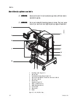
Page 14: ...Aestiva 1 8 1006 0938 000 1 8...

Page 15: ...ction Anesthesia system controls 2 2 Breathing system controls 2 5 Vaporizer controls 2 9 Ventilator controls 2 11 Optional flowmeter and suction regulators 2 19 Optional CO2 Bypass mode operation 2 2...

Page 16: ...ng tubes or masks They can cause burns if you use them near high frequency surgical equipment 1 Breathing system Figure 2 3 2 Flow controls 3 Ventilator monitoring display Figure 2 5 4 Light switch an...

Page 17: ...turn on the monitoring Flow controls Turn the control counterclockwise to increase the flow and clockwise to decrease The system switch must be on O2 flush Push O2 Flush to supply high flows of O2 to...

Page 18: ...aker for Total Outlet Current 4 Circuit Breaker for Mains Inlet 5 Mains Inlet 6 Ventilator fuse 7 Pneumatic Outlet 8 Pipeline Connection Figure 2 2 Aestiva rear view Item Description Figure 2 2 Circui...

Page 19: ...ction circuit connections a Inspiratory Circle circuit module or to fro connection Mapleson Bain circuit module b Expiratory Circle circuit module or fresh gas connection Mapleson Bain circuit module...

Page 20: ...athing system pressure during manual ventilation The scale shows approximate pressures Above 30 cmH2O you will feel clicks as the knob turns Bag arm One arm is adjustable push in and turn The other is...

Page 21: ...ptional Pulling and turning the canister release opens the canisters and activates the CO2 bypass mode The CO2 bypass seals the breathing circuit when the canisters are open This permits continued ven...

Page 22: ...al Sends fresh gas to the selected outlet when the system has an auxiliary common gas outlet Monitoring and ventilation turn off when the auxiliary outlet is selected Item Description Breathing system...

Page 23: ...lockwise to lock the vaporizer in position Concentration control and release Push the release and turn the concentration control to set the agent concentration The Tec 6 concentration control does not...

Page 24: ...m Description Lock before use 2 W a r n in g K e e p u p ri g h t a t a ll ti m e s Se e m an u al fo r O p er at io n al In st ru ct io n s F ac to rs af fe ct in g p er fo rm an ce Se rv ic e an d m...

Page 25: ...th these functions Control panel Ventilator controls include Touch keys Menu screens A control knob 1 Alarm silence key 2 Alarm message display 3 Volume alarms On Off key 4 Menu key 5 Breathing circui...

Page 26: ...ventilation Item Description Menu key Shows the main menu Alarm silence key and indicator Silences most alarms for 120 seconds Pushing the key when no alarm is active pre silences low and medium prior...

Page 27: ...ns user selections to the most common settings Cardiacbypassoff Alarmlimitsshown and Heliox mode off Sets the PEEP to 0 cmH2O default value Sets Plimit to one of two values facility default or 4 4 4 4...

Page 28: ...tone will sound or a message will appear on the screen If the incorrect key is pushed wait ten seconds or push the correct key If the new setting is not saved the ventilator continues to use the old s...

Page 29: ...l display 25 seconds after the last action During a calibration or other procedure the screen shows the instructions Step 1 Push the Menu key to see the main menu Step 2 Turn the knob to select an opt...

Page 30: ...table tells you about some of the options Figure 2 6 Menu map AB 90 036 AB 90 054 SE N N N No o o ot t t te e e e If the Alarm Settings page shows E Auto Limits during mechanical ventilation the syste...

Page 31: ...itional ventilation settings for SIMV and PSVPro modes O2 Sensor Cal Shows menu for O2 sensor calibration Inspiratory Pause Adds an inspiratory pause time to volume control breaths Heliox mode On Off...

Page 32: ...ts The screen goes back to the normal display 25 seconds after the last action Step 1 Select the desired menu Step 2 Turn then push the knob to select an option Step 3 Turn the knob to change the sett...

Page 33: ...r outlet 2 External O2 flowmeter 3 Suction regulator 4 Suction mode switch On Off MAX 5 Vacuum gauge 6 Suction adjustment 7 Vacuum inlet non venturi models only 8 Collection bottle connection 9 Overfl...

Page 34: ...r l Off O to turn Off suction set the switch to O With a venturi regulator 2 Modes On foradjustablesuction settheswitchtoOn or l Off O to turn Off suction set the switch to O With the mode switch set...

Page 35: ...arm is downgraded to low priority after silenc ing Close the absorber canisters to activate the Absorber mode Closing the can isters directs exhaled gas flow through the absorber removing CO2 Do the b...

Page 36: ...Aestiva 2 22 1006 0938 000...

Page 37: ...he system 3 2 Set the alarm loudness 3 3 Show or hide alarm limits and units 3 5 Adjust patient data for Heliox 3 7 Turn the volume alarms on or off 3 8 Set alarm limits 3 9 Set an audible alarm for c...

Page 38: ...ower is connected Step 2 Set the system switch to On Step 3 The display shows the power up screen and the system does a series of self tests Step 4 When the self tests pass the display shows the norma...

Page 39: ...Set the alarm loudness Step 1 Select the Screen and Audio Setup menu Push the menu key Turn then push the knob to select Screen and Audio Step 2 Turn then push the knob to select alarm loudness AB 29...

Page 40: ...tiva 3 4 1006 0938 000 Step 3 Turn then push the knob to adjust the volume The volume range is 1 to 5 loudest As the volume is changed the system sounds test tones Push the knob to save the change The...

Page 41: ...s the limits when An alarm occurs Volume alarms are off or the auxiliary common gas outlet is selected monitoring off An individual alarm limit is set to Off When the system is set to Standby alarm li...

Page 42: ...6 1006 0938 000 Step 2 Turn then push the knob to select Alarm Limits or Units of Measure Step 3 Turn then push the knob to select Show or Hide Push the knob to save the change AB90 063 AB90 044 Then...

Page 43: ...to systems equipped with these functions When the Heliox mode is selected the system automatically corrects measurements for the lower density of Heliox compared to air w W W W WA A A AR R R RN N N NI...

Page 44: ...volume alarms on and off When the alarms are off a large X covers the limits Use this control to prevent false alarms if you switch to manual ventilation at lower tidal volumes Use the End Case key on...

Page 45: ...Auto Limits during mechanical ventilation the system is set to automatically calculate E limits Step 1 Select the Alarm Settings menu Push the menu key Turn then push the knob to select Alarm Settings...

Page 46: ...3 10 1006 0938 000 Step 3 Turn then push the knob to change the limit Push the knob to save the change The screen returns to the normal display 25 seconds after the last change T T T Th h h he e e en...

Page 47: ...n leak e g an un cuffed endotracheal tube set the audio to Off Normal volume and apnea monitoring does not change N N N No o o ot t t te e e e This alarm is the first stage in detecting a circuit disc...

Page 48: ...shows Cardiac Bypass Apnea Alarm Off Vol Alarms Off Note The mechanical ventilation must be off When the mechanical ventilation is turned back on Cardiac Bypass returns to the No Bypass setting and al...

Page 49: ...0938 000 3 13 3 Step 1 Select the Cardiac Bypass menu item Push the menu key Turn then push the knob to select Cardiac Bypass In Progress Step 2 Push the knob again to return to No AB 29 013 AB 90 036...

Page 50: ...rt or stop ventilation Mechanical ventilation is off when you first turn on the system Step 1 Make sure the control settings are OK Step 2 Turnofftheauxiliarycommongasoutlet some models Step 3 Set the...

Page 51: ...A A A AR R R RN N N NII I IN N N NG G G G Make sure the patient circuit is correctly assembled and the control settings are correct before you start or stop ventilation Step 1 Make sure control settin...

Page 52: ...olume controlled modes supply a set tidal volume AB 90 092 Step 1 Select the Ventilation Mode Push the menu key PushtheknobtoselectVentilation Mode Step 2 Turn then push the knob to change the mode Pu...

Page 53: ...mode has one parameter that must be set VT for Volume and SIMV PinspiredforPressure andPsupportfor PSVPro Turn then push the knob to set the value Until a value is set the ventilator shows If any othe...

Page 54: ...tilator controls present are based on the ventilation mode Messages appear on the screen if You try to set a value the system cannot supply You change a setting but do not save it Push knob to confirm...

Page 55: ...not use a separate mechanical PEEP valve incorrect operation and patient injury can result Pinspired This control sets the amount of pressure delivered to the patient in each pressure controlled brea...

Page 56: ...ol settings Pressure Control mode The figure and table below show Pressure Control settings SIMV mode The figure and table below show SIMV settings Settings VT Rate I E Plimit PEEP Range 20 1500 4 100...

Page 57: ...tilate the patient using the SIMV PC PSV mode All parameters shown are active in this mode Settings VT Rate Tinspired Psupport PEEP Range 20 1500 2 60 0 2 5 0 Off 2 40 Off 4 30 Increments varies 1 bpm...

Page 58: ...se is on the inspiratory volume stays in the patient s lungs for the set pause time at the end of inspiration Pause can be set from Off to 60 percent of inspiratory time in increments of five percent...

Page 59: ...and Tutorial 1006 0938 000 3 23 3 Step 2 Turn then push the knob to select Inspiratory Pause Step 3 Turn then push the knob to change the setting You must push the knob to save the change AB 90 083 20...

Page 60: ...ion menu Step 1 Select the SIMV PSVPro Setup menu Push the menu key Turn then push the knob to select Setup Calibration Step 2 Push the knob to select SIMV PSVPro Setup wWARNING Most anesthetic agents...

Page 61: ...ration and Tutorial 1006 0938 000 3 25 3 Step 3 Turn then push the knob to select a setting Step 4 Turn then push the knob to change the setting You must push the knob to save the change AB 90 073 40...

Page 62: ...must be silenced individually Alarm tones identify the alarm priority High Priority 10 tones 10 seconds pause repeat Medium Priority 3 tones 25 seconds pause repeat Low Priority single tone Alarms app...

Page 63: ...ate 25 or less breaths per minute time scale is 0 to 16 seconds 26 to 75 breaths per minutes time scale is 0 to 8 seconds 76 or more breaths per minutes time scale is 0 to 4 seconds On a change existi...

Page 64: ...m sensed inspiratory pressure Pmax 25 Mean positive airway pressure Pmean 11 Figure 3 1 Paw waveform in Volume Control mode Example Pressure Control Pmax 34 Upper pressure limit Plimit 40 PEEP 10 Figu...

Page 65: ...IMV Plateau pressure Ppl 15 Inspiratory time Tinspired 1 5 Inspiratory Pause 60 Figure 3 3 Paw waveform in SIMV mode Example PSVPro PEEP 5 Pressure support 10 Mean positive airway pressure Pmean 7 Fig...

Page 66: ...dal volume VTE and Pmax measured peak airway pressure The VTE measures the gas needed to fill the patient circuit at the measured pressure The example shows how tubing compliance factor can be calcula...

Page 67: ...ou turn it off or goes back to facility defaults Altitude Used for gas calculations If the altitude is not correct O2 calibration can fail Drive gas O2 or Air Tells you which gas the ventilator uses t...

Page 68: ...Aestiva 3 32 1006 0938 000 Step 2 Turn then push the knob to select About Ventilator AB 90 045 AB 90 047 AB 90 051...

Page 69: ...ronments which have no dedicated vacuum system for waste gas disposal The disposal system generally consists of large diameter tubing and or duct directly linking the passive AGSS with the building ex...

Page 70: ...ri ejector systems having their own extract flowmeter This will operate satisfactorily with a minimum extract flow of 30 L min to 100 L min but there is no built in flow indicator All three versions a...

Page 71: ...scavenge gas from a gas monitor connect tubing from the monitor to the 3 18 mm 1 8 inch hose barb g in the breathing system base Step 3 With the AGSS operating verify that the flow indicator ball d o...

Page 72: ...en 30 and 100 L min To use the optional active AGSS installed on the system which does not have a flow indicator connect it as follows Step 1 Connect a nominal 1 2 inch ID hose to the AGSS outlet hose...

Page 73: ...stem connections The warnings and cautions How to use each system component How to test each system component wW W W WA A A AR R R RN N N NII I IN N N NG G G G Before you use this system Complete the...

Page 74: ...flow to drive down N2O flow The O2 flow is nominal 25 O2 supply failure alarm Alarm operates when O2 pressure is decreased below set limit Air flow continues All other gases stop Do the vaporizer back...

Page 75: ...ure each vaporizer is locked and cannot be removed Make sure the alarms and indicators operate correctly Tec 6 vaporizer Makesureyoucannotturnonmorethanonevaporizeratthesametime Do the breathing syste...

Page 76: ...Aestiva 4 4 1006 0938 000...

Page 77: ...very day before the first patient A 3 Precase steps A 11 Every time a different clinician uses the system A 12 Low pressure leak test A 12 Before every patient A 16 Breathing system tests A 19 Monitor...

Page 78: ...G G G G Do not use this system unless you have read each component s operation and maintenance manual and understand All system connections All of the warnings and cautions How to use each system comp...

Page 79: ...ressures are correct 6 Cylinder valves are closed on models with cylinder supplies w w w w W W W WA A A AR R R RN N N NII I IN N N NG G G G Do not leave gas cylinder valves open if the pipeline supply...

Page 80: ...ct the power cord to a wall outlet The mains indicator comes On when AC Power is connected If the indicator is not on the system does not have mains electrical power Use a different outlet Close the c...

Page 81: ...cylinder pressure gauges are not at zero Connect an O2 supply Turn On the system if it is not already on Set the flow controls to mid range Make sure that all gauges but O2 go to zero Disconnect the O...

Page 82: ...se cylinder valves w w w w W W W WA A A AR R R RN N N NII I IN N N NG G G G Do not leave gas cylinder valves open if the pipeline supply is in use Cylinder supplies could be depleted leaving an insuff...

Page 83: ...ockwise minimum flow 3 Turn on the system 4 Do not use the system if low battery or other ventilator failure alarms occur 5 Make sure the O2 flowtube shows approximately 25 to 75 mL min The other flow...

Page 84: ...12 Reconnect the pipeline supplies Vaporizer back pressure test w w w w W W W WA A A AR R R RN N N NII I IN N N NG G G G Anesthetic agent comes out of the common gas outlet during this test Use a saf...

Page 85: ...before use 2 W a r n in g K e e p u p ri g h t a t a ll ti m e s Se e m an u al fo r O p er at io n al In st ru ct io n s F ac to rs af fe ct in g p er fo rm an ce Se rv ic e an d m ai n te n an ce re...

Page 86: ...o 5 L min 6 Make sure that The end expiratory pressure is approximately 0 cmH2O The ventilator displays the correct data The bellows inflate and deflate during mechanical ventilation 7 Test the O2moni...

Page 87: ...t the low airway pressure and apnea alarms occur The apnea alarm occurs after 30 sec 11 Test the sustained airway pressure alarm Set the controls Mechanical ventilation stops when the Bag Vent switch...

Page 88: ...A A AR R R RN N N NII I IN N N NG G G G Do not use a system with a low pressure leak Anesthetic gas will go into the atmosphere not into the breathing circuit Low pressure leak test Negative low pres...

Page 89: ...ect the test device 7 Test each vaporizer for low pressure leaks Set the vaporizer to 1 Repeat step 6 If there is a low pressure leak refer to the Setup Maintenance and Troubleshooting Manual 8 Keep t...

Page 90: ...on gas outlet 1 Access the common gas outlet CGO 2 Connect the leak test device to the common gas outlet with a section of tubing Turn off the auxiliary common gas outlet Set the Outlet switch to comm...

Page 91: ...p Maintenance and Troubleshooting Manual 9 Repeat this low pressure leak test for each vaporizer Set the applicable vaporizer to 1 and do steps 2 through 8 Fully open the needle valve on the test devi...

Page 92: ...damaged and contains sufficient absorbent 4 The vaporizers are locked in position and contain sufficient agent 5 Pipeline gas supplies are connected and the pressures are correct 6 Cylinder valves ar...

Page 93: ...t 12 Connect the power cord to a wall outlet The mains indicator comes on when AC Power is connected If the indicator is not on the system does not have mains electrical power Use a different outlet C...

Page 94: ...sethisanesthesiasystemifyoucanturnonmorethanone vaporizer at the same time Tec6vaporizerswillnotaligncorrectlyunlessthepowercablegoes through the channel on the bottom of the vaporizer Do not put the...

Page 95: ...rn if the operational indicator is off 6 Try to turn on more than one vaporizer at the same time Test each possible combination If more than one vaporizer turns on at the same time remove the vaporize...

Page 96: ...tem w w w w W W W WA A A AR R R RN N N NII I IN N N NG G G G Makesurethattherearenotestplugsorotherobjectscaughtinthe breathing system 5 Test the ventilator circuit for leaks Set the Bag Vent switch t...

Page 97: ...the APL valve Makesurethatthevalueontheinspiratorypressuregaugedecreasesto approximately zero Push the flush button and make sure that the value on the inspiratory pressure gauge stays near zero Set...

Page 98: ...iately set the system switch to Standby and close all cylinder valves 9 Make sure that you have Equipment for airway maintenance manual ventilation tracheal intubation and IV administration Applicable...

Page 99: ...ps ventilation 3 14 Auxiliary outlet switch function 2 8 B Bag arm adjust position 2 6 location 2 5 Bag Vent switch function 2 6 how to stop mech vent 3 15 start mechanical ventilation 3 14 Bag vent s...

Page 100: ...2 11 Mains inlet location 2 4 Measured values display 2 11 Mechanical ventilation how to start 3 1 3 14 how to stop 3 15 Menu how to change menu settings 2 18 how to change settings 2 18 how to use 2...

Page 101: ...u options 2 17 Setup Calibration menu 3 7 3 22 3 31 Shelf weight limit A 3 Show hide alarm limits 3 4 units 3 4 SIMV controls 3 24 Software version 3 31 Suction regulator controls 2 20 location 2 19 S...

Page 102: ...Aestiva I 4 1006 0938 000...

Page 103: ...foregoing warranties shall not apply if the Product has been repaired other than by Datex Ohmeda or in accordance with written instructions provided by Datex Ohmeda or altered by anyone other than Da...

Page 104: ...l 82 2 786 7421 Fax 82 2 786 7420 Malaysia Datex Ohmeda Pte Ltd Level 2 Bangunan O Connor 13 Jalan 223 46100 Petaling Jaya Selangor West Malaysia Tel 60 3 754 7872 Fax 60 3 757 6948 Singapore Datex Oh...

Reviews: