The Model IL78A is a single
-
channel conditioner of
phase-sensitive carrier-amplifier
design.
Intended for applications involving transformer-coupling to the transducer bridge (as with rotary-
transformer torque sensors), this conditioner can also be used in conventional installations when
high sensitivity is required or where the electrical environment is especially noisy. Responding
only to the modulated carrier frequency, the IL78A rejects extraneous voltages that can cause
errors in DC systems, particularly when there is a need to “blow up” a portion of the transducer
range. User-adjustable phase and symmetry controls are provided.
1
G
ENERAL
D
ESCRIPTION AND
S
PECIFICATIONS
IN-LINE AC Strain Gage Conditioner
M
ODEL
IL78A
AC Strain Gage
C
ONDITIONER
Module
IL78A
GENERAL DESCRIPTION AND SPECIFICATIONS IL78A.1
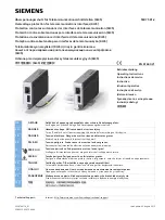
Top View of the Model IL78A AC Strain Gage Module (cover removed)
AC Strain Gage Phase Operation
Due to the AC modulated aspects of the IL78A AC Voltage excitation circuit, the IL78A8 contains a "PHASE"
adjustment which aligns the transducer's return output signal to the conditioner's demodulator. When the
demodulator is aligned properly through calibration, maximum amplitude and linearity are achieved.
The Model IL78A's is calibrated by means of a “two-point (dead-weight)” or
shunt-calibration
technique, which are outlined in section three. The user can utilize the shunt calibration method
by adding the correct leaded shunt resistor value from "Cal Sense" to Sense or - Sense
depending on the polarity desired.
Shunt
Operation:
Located between the two screw terminal connectors, the IL70A contains a Shunt resistor jumper
selection. "EXT" is for an external - user installed shunt or "INT" for the internal - built in - 59K Ohm shunt. Installing the jumper
enables the selected feature. For an external shunt resistor, install the leaded resistor between the "Cal Sense" (pin 7) terminal
and either the + Signal (pin 5) or the - Signal (pin 6) terminals. Use the SW4 "Shunt" button to engage the shunt resistor across
the selected side of the bridge or "SHP or "SHN" logic input lines. For transducers with an installed shunt resistor, place the
jumper on the "EXT" teminals and wire the "Cal Sense" line to the transducer's shunt connector pin.
92371.00 rev.
B


