background image

ELECTRONIC DRUM SET
U S E R M A N U A L

BETA PRO

Summary of Contents for BETA PRO

Page 1: ...ELECTRONIC DRUM SET U S E R M A N U A L BETA PRO ...

Page 2: ...nd even death Please operate the machine according to instructions Object damage refers to any harm or adverse effects to household furniture pets and etc About Signs This sign indicates a warning or caution Please read the accompanied instruction to prevent any dangers This sign indicates any forbidden activity This sign indicates an instructional procedure for users to follow with ALWAYS FOLLOW ...

Page 3: ...safely WARNING Please only use the adapter that is in cluded with the unit Make sure that the voltage of the socket matches the voltage indicated on the unit Please do not over twist or over bend the power cable or place any objects on it Doing so may result in short circuit that can lead to fire and electric shock Should any of the following situations result please stop operation and remove the ...

Page 4: ...d out correct voltage for that country CAUTION Always place the module and the adaptor in areas with good airflow When inserting or removing the power cable into from the socket or the machine always grab the plug instead of the cable If you do not plan to operate the module for a long period of time please remove the adapter from the socket To prevent the cables from tangling place the cables out...

Page 5: ...er use volatile oil diluting solutions alcohol or any other kinds of solvents to prevent the machine from deforming or discoloring Additional Precautions During operation please handle with care to prevent any damage Do not hit or press against the display screen Always grab the heads of cables during in sertion removal to prevent damage to the cables or the machine To prevent disturbing your neig...

Page 6: ...Pad Ø3 81 cm Stopper Wing Bolt Nut x4 x2 x4 x27 x26 x2 Accessories A1 A2 A3 A4 A5 A6 Sound Module Pad Cymbal Hi hat Controller Kick Pedal Bass Drum Double Slip Resistant Tape x1 x4 x3 x1 x1 x1 L1 L2 Adapter L L Mono Sound Cable 1 x1 Adjustable Bar x3 Ø3 81 Ø2 22 Connector Adjustable C4 x1 WARNING Please note whenever you insert or pull the plug out of a socket or adapter hold the plug Do not pull ...

Page 7: ... Stand Ø3 81cm S1 40cm X1 2 S2 57cm X1 S3 40cm X1 2 S4 75cm X1 x2 S5 57cm X1 x2 S6 75cm X1 2 S7 40cm X1 x1 S8 57cm X1 x1 x1 S9 57cm X1 x1 x1 x1 S11 40cm X3 Ø1 27cm Ø2 22cm S12 20cm X4 S1 S7 S8 S9 S2 S2 S3 S4 S5 S6 x1 S2 6 ...

Page 8: ...Step 1 P4 x18 P5 X18 B4 x4 x1 x4 x1 Attention When assembling this connector tighten each of the bolts in a square pattern Do not tighten one bolt at a time This will cause the connector to be uneven 7 ...

Page 9: ...Step 2 S1 40cm x1 left S2 57cm x1 center S3 40cm x1 right P1 x4 57cm 40cm S1 S2 40cm S3 P1 P1 P1 P1 8 ...

Page 10: ...3 2 75cm 75cm 57cm S4 S5 S6 Step 3 S4 75cm x1 left S5 57cm x1 center S6 75cm x1 right Please note the direction of the screw 9 ...

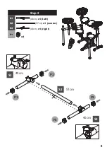
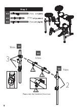
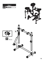
Page 11: ... S7 40cm Step 4 S7 40cm x1 10 ...

Page 12: ...S8 57cm 57cm P2 57cm P2 S9 57cm Step 5 S8 57cm x1 S9 57cm x1 S10 57cm x2 P2 x2 Please note the direction of the screw S10 S10 11 ...

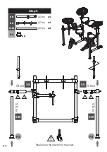
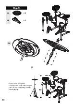
Page 13: ...S11 S11 S11 Step 6 S11 Ø2 22 x40 cm x3 S12 Ø1 27 x20 cm x4 C3 x3 C4 x1 12 ...

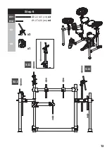
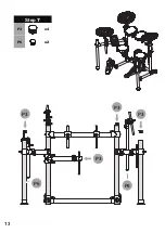
Page 14: ...P3 P6 P3 P3 P3 Step 7 P3 x4 P6 x2 P6 13 ...

Page 15: ...Step 8 A2 x4 P4 x8 C1 x4 P5 x8 A2 P5 P4 C1 A2 Groove Convex Match the convex side of pad with the groove side of connector 14 ...

Page 16: ...A5 A4 Step 9 A4 x3 A5 x1 ZZ Hi hat and Hi hat pedal correspond to each other as open close Hi hat simulating realistic Hi hat playing 15 ...

Page 17: ...Step 10 P4 x1 A7 x1 A6 x1 Step 3 A6 Step 2 Step 1 P4 A5 The slip resistant tape compensate for varying kick pedal heights or 16 ...

Page 18: ...Mounting on the stand A1 x1 C2 x1 Position the Sound Module onto the Bar and fold the U Shape plate upwards around the bar Secure the U Shape plate to the back of the sound module with screws C2 A1 17 ...

Page 19: ...the Tom 1 and Tom 2 for smoother playing 3 To make it more realistic tighten the nut to adjust the Hi hat loosen the nut to adjust Cymbal 1 Cymbal 2 4 Adjust the position and height of the other pads 5 Check that all screws have been tighten Hi hat Snare Tom 1 Crash Ride Tom 2 Tom 3 Kick tighten loosen loosen Tom 1 Tom 2 Snare Tom 3 Hi hat tighten loosen Cymbal 1 Cymbal 2 HH ctrl 18 ...

Page 20: ...nd Cable L2 WARNING Please note whenever you insert or pull the plug out of a socket or adapter hold the plug Do not pull on the cable STEP 1 STEP 2 Lock Lock B6 Velcro no provide Controller A4 x1 B6 X6 19 ...

Page 21: ...White Tom 1 Orange Crash Red Ride Green Snare Yellow HH ctrl Blue Tom 2 Purple Tom 3 Black Kick Gray PHONES LINE IN LINEOUT LEFT LINEOUT RIGHT EFFECT 1 EFFECT 2 EFFECT 3 MICRO SD USB MIDI OUT HH ctrl HH ctrl 20 ...

Page 22: ...B2 x2 For the cables use the bolts like a hook and let the cable run alongside the mounting rack Leave some buffer for the cable so there is no stress on the connectors Use the cable tie to secure cable B2 B2 21 ...

Page 23: ...ontinuous Type Half open tone transition Full open Full close Foot splash Snare Some snare sound are not supported Rim Shot Choke effect After hitting the cymbal you can grab the rim as illustrated to produce realistic muted cymbal sound Hi hat Crash Ride 2 zone choke Bell Strike cymbal weakly Bow Strike cymbal strongly Bell Bow Edge 22 ...

Page 24: ...For more information please visit our website www ddrum com ...

Reviews:

Related manuals for BETA PRO