background image


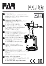
GO 212 

Pour Rivets Standards Ø 3.2 à 4.8 mm 

Alu, Acier, Inox


For Standards Rivets Ø 3.2 to 4.8 mm 

Alu, Steel, St Steel


GO 182 

Pour Rivets Standards Ø 4.0 à 6.4 mm 

Alu, Acier, Inox


Pour Rivets de Structure Ø 4.8 à 6.4 mm 

Alu, Acier, Inox 

For Standard Rivets Ø 4.0 to 6.4 mm 

Alu, Steel, St Steel


For Structural Rivets Ø 4.8 to 6.4 mm 

Alu, Steel, St Steel


GO 212 / GO 182

CONSIGNES DE SÉCURITÉ ET MODE D'EMPLOI 

SAFETY INSTRUCTIONS AND DIRECTIONS FOR USE

Summary of Contents for GO 182

Page 1: ... 182 Pour Rivets Standards Ø 4 0 à 6 4 mm Alu Acier Inox Pour Rivets de Structure Ø 4 8 à 6 4 mm Alu Acier Inox For Standard Rivets Ø 4 0 to 6 4 mm Alu Steel St Steel For Structural Rivets Ø 4 8 to 6 4 mm Alu Steel St Steel GO 212 GO 182 CONSIGNES DE SÉCURITÉ ET MODE D EMPLOI SAFETY INSTRUCTIONS AND DIRECTIONS FOR USE ...

Page 2: ...EN SERVICE 5 4 CHANGEMENT DES NEZ 6 5 ENTRETIEN MAINTENANCE 7 6 VUE ÉCLATÉE 13 7 GARANTIE CERTIFICATION CE 16 1 GO 212 GO 182 PRESENTATION 17 2 SECURITY 18 3 PREPARATION 19 4 CHANGING NOSE ASSEMBLIES 20 5 MAINTENANCE 21 6 EXPLODED DRAWING 27 7 WARRANTY CE CERTIFICATION 30 ...

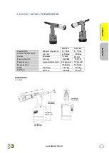
Page 3: ...s 4 3 litres Course Minimum 17 mm 28 mm Force de traction À 5 5 bar 9 30 kN 15 0 kN Temps de cycle Approximativement 0 9 second 1 0 second Niveau de bruit 75 db A 75 db A Poids Sans Nez 1 57 kg 1 95 kg Vibration Moins de 2 5 m s2 2 5 m s2 DIMENSIONS en mm 118 GO212 133 GO 182 286 GO212 322 GO 182 128 GO212 148 GO 182 104 GO212 125 GO 182 FRANCAIS ENGLISH ...

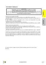
Page 4: ...santé et de sécurité Toute question concernant le fonctionnement correct de l outil et la sécurité de l opérateur doit nous être adressée 6 Les précautions à prendre lors de l utilisation de cet outil doivent être expliquées par le client à tous les opérateurs 7 Toujours déconnecter la conduite d air de l entrée de l outil avant d essayer d ajuster de monter ou de démonter un nez 8 Ne pas utiliser...

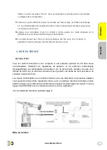
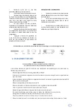
Page 5: ...oin de bien se laver 3 MISE EN SERVICE Arrivée d Air Tous les outils fonctionnent à l air comprimé à une pression optimale de 5 5 bars Nous recommandons l utilisation de régulateurs de pression et de systèmes automatiques d huilage filtrage sur l alimentation principale en air Ils doivent être installés à moins de 3 mètres de l outil voir le schéma ci dessous pour garantir une durée de vie maximal...

Page 6: ...on soit suffisante pour retenir l attache IMPORTANT L alimentation en air doit être déconnectée lors du montage ou du démontage des nez 4 CHANGEMENT DES NEZ IMPORTANT Les ensembles de nez ne comprennent pas d embouts Les embouts doivent être commandés séparément Les numéros d articles en gras font référence aux composants de l assemblage du nez dans tous les tableaux de pointes de nez Enduire légè...

Page 7: ...Débrancher l alimentation en air Retirez tous les éléments de l assemblage du nez Retirer l écrou de retenue 22 et tous les éléments du collecteur de tige points 18 19 20 21 45 63 64 Notez que l anneau O 17 reste Remplacer l élément ci dessus par un bouchon de sécurité comme indiqué sur le dessin ci contre Dévisser le boîtier de l écarteur de mâchoires 1 et le retirer avec le joint torique 2 le co...

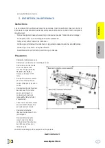
Page 8: ...mment mesurer la course Un collecteur de tige ou un déflecteur de tige doit être installé sur l outil à moins qu une tête pivotante ne soit installée Vérifiez que le couvercle de base 36 est complètement serré sur le corps 34 Assurez vous que la vanne rotative 60 est correctement réglée pour la rétention du rivet voir Procédure d utilisation CHAQUE SEMAINE Démontez et nettoyez l ensemble nez en po...

Page 9: ...s conseillons de procéder au démontage des sous ensembles dans l ordre indiqué Après tout démontage N OUBLIEZ PAS d amorcer l outil et d installer un nez ou une tête pivotante approprié ASSEMBLAGE DE LA TETE démontage Dévissez l écrou de retenue 22 et retirez l ensemble collecteur de tige articles 18 19 20 21 45 63 64 et la bague Q 17 Retirer l adaptateur collecteur de tige 13 À l aide de la clé e...

Page 10: ...ec le joint torique 35 le joint à lèvre 37 et la bague de guidage 3 1 Visser l extracteur de joint dans l ensemble de joint 30 et le retirer du tube multiplicateur de l ensemble de tête 4 Assembler dans l ordre inverse du démontage ASSEMBLAGE DE LA BOBINE DE SOUPAPE Retirez l ensemble piston pneumatique 38 et l ensemble joint 30 comme décrit immédiatement ci dessus À l aide de la clé en T et de l ...

Page 11: ...outil et mettez la vanne MARCHE ARRÊT 55 en position MARCHE Vérifiez que la course de l outil correspond à la spécification minimale de 26 millimètres Pour vérifier la course mesurer la distance entre la face avant du boîtier de l écarteur de mâchoires 1 et la face avant de la tête AVANT d appuyer sur la gâchette et lorsque la gâchette est complètement actionnée La course est la différence entre l...

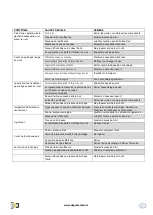
Page 12: ...rvice Le logement de la mâchoire la pointe du nez ou le boîtier du nez ne sont pas correctement installés Serrer l assemblage du nez Ressort faible ou cassé dans le nez Monter un nouveau ressort Fuite d air ou d huile Serrer les joints ou remplacer les composants Niveau d huile bas ou présence d air dans Re préparer et amorcer l outil Impossible d alimenter le rivet suivant Tiges cassées coincées ...

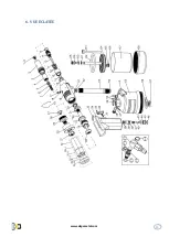
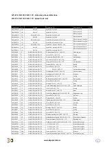
Page 13: ...13 www degometal com 6 VUE ÉCLATÉE ...

Page 14: ...182 GO 172 Boîtier d étanchéité GO 212 182 172 Seal housing 1 Z02120014 14 GO 212 GO 182 GO 172 Joint GO 212 182 172 O ring 1 Z02120015 15 GO 212 GO 182 GO 172 Rondelle GO 212 182 172 Seal 1 Z02120016 16 GO 212 GO 182 GO 172 Corps assemblage tête GO 212 182 172 Head assembly 1 Z02120017 17 GO 212 GO 182 GO 172 Vis GO 212 182 172 Screw 1 Z02120018 18 GO 212 GO 182 GO 172 Rondelle GO 212 182 172 Sea...

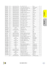
Page 15: ...uyau GO 212 182 Tube 1 Z02120054 54 GO 212 GO 182 GO 172 Joint GO 212 182 172 O ring 1 Z02120055A 55 GO 212 Corps GO 212 Body 1 Z01820055B 55 GO 182 GO 172 Corps GO 182 172 Body 1 Z02120056 56 GO 212 GO 182 GO 172 Plaque de serrage GO 212 182 172 Clamp plate 1 Z02120057 57 GO 212 GO 182 GO 172 Ecrou de serrage GO 212 182 172 Clamp nut 1 Z02120058 58 GO 212 GO 182 GO 172 Joint GO 212 182 172 Lip se...

Page 16: ...onformité Nous déclarons par la présente que cet outil lorsqu il est utilisé et entretenu conformément aux codes de bonne pratique généralement acceptés et aux recommandations du manuel d instructions répondent aux exigences essentielles de sécurité et de santé de la directive Machines 2006 42 CE Pour les risques les plus spécifiques de cet outil la sécurité et le respect des exigences essentielle...

Page 17: ...s 4 3 litres Stroke Minimum 17 mm 28 mm Pull Force 5 5 bar 9 30 kN 15 0 kN Cycle time Approximately 0 9 second 1 0 second Noise Level 75 db A 75 db A Weight Without nose equipment 1 57 kg 1 95 kg Vibration Less than 2 5 m s2 2 5 m s2 DIMENSIONS in mm FRANCAIS ENGLISH 118 GO212 133 GO 182 286 GO212 322 GO 182 128 GO212 148 GO 182 104 GO212 125 GO 182 ...

Page 18: ...dance with relevant Health and Safety legislation Any question regarding the correct operation of the tool machine and operator safety should be directed to us 6 The precautions to be observed when using this tool machine must be explained by the customer to all operators 7 Always disconnect the airline from the tool machine inlet before attempting to adjust fit or remove a nose assembly 8 Do not ...

Page 19: ...voided To minimize the possibility of rashes care should be taken to wash thoroughly 3 PREPARATION AIR SUPPLY All tools are operated with compressed air at an optimum pressure of 5 5 bar We recommend the use of pressure regulators and automatic oiling filtering systems on the main air supply These should be fitted within 3 metres of the tool see diagram below to ensure maximum tool life and minimu...

Page 20: ...and hold it into position Turn the rotary valve either way until there is sufficient suction to retain the fastener IMPORTANT The air supply must be disconnected when fitting or removing nose assemblies 4 CHANGING NOSE ASSEMBLIES IMPORTANT Nose assemblies do NOT include nose tips Nose tips must be ordered separately Item numbers in bold refer to nose assembly components in all nose tip tables Ligh...

Page 21: ...ing nut 22 and all elements of the stem collector items 18 19 20 21 45 63 64 Note that O ring 17 remains Replace the above with a safety cap as shown in drawing opposite Unscrew jaw spreader housing 1 and remove with O ring 2 locknut 3 O rings 65 and 66 and seal housing 5 Screw stop nut onto the front of Head Piston 7 as far as it will go by hand Re fit jaw spreader housing 1 and O ring 2 Unscrew ...

Page 22: ... is fitted Check that Base Cover 36 is fully tightened onto body 34 Ensure that rotary valve 60 is correctly adjusted for fastener retention see Operating Procedure page 6 WEEKLY Dismantle and clean the nose assembly with special attention to the jaws Lubricate with Maly Lithium grease before assembling Check for oil leaks and air leaks in the air supply hose and fittings MOLY LITHIUM GREASE EP 37...

Page 23: ...ool it is necessary to remove the nose equipment For instructions see the nose equipment section For a complete service of the tool we advise that you proceed with dismantling of sub assemblies in the order shown After any dismantling REMEMBER to prime the tool and to fit an appropriate nose assembly or swivel head HEAD ASSEMBLY Unscrew retaining nut 22 and pull off stem collector assembly items 1...

Page 24: ...fitted with soft jaws Using the peg spanner unscrew base cover 36 and pullout cylinder liner 41 Remove pneumatic piston assembly 38 from body 34 together with O ring 35 lip seal 37 and guide ring 31 Screw the seal extractor into seal assembly 30 and pull it out of the intensifier tube of head assembly 4 Assemble in reverse order to dismantling VALVE SPOOL ASSEMBLY Remove pneumatic piston assembly ...

Page 25: ... Remove the priming pump and the stop nut Replace bleed screw 9 and seal 10 Connect air supply to tool and switch ON OFF valve 55 to ON position Check that the stroke of the tool meets the minimum specification of 26 millimetres To check the stroke measure the distance between the front face of jaw spreader housing 1 and the front face of the head BEFORE pressing the trigger and when the trigger i...

Page 26: ...e the nose assembly Service nose assembly Jaw housing nose tip or nose casing not properly seated Tighten nose assembly Weak or broken spring in nose assembly Fit new spring Air or oil leak Tighten joints or replace components Low oil level or air present in oil Prime tool Cannot feed next fastener Broken stems jammed inside tool Empty stem collector Check jaws spreader is correct Adjust air press...

Page 27: ...27 www degometal com 6 EXPLODED DRAWING ...

Page 28: ...182 GO 172 Boîtier d étanchéité GO 212 182 172 Seal housing 1 Z02120014 14 GO 212 GO 182 GO 172 Joint GO 212 182 172 O ring 1 Z02120015 15 GO 212 GO 182 GO 172 Rondelle GO 212 182 172 Seal 1 Z02120016 16 GO 212 GO 182 GO 172 Corps assemblage tête GO 212 182 172 Head assembly 1 Z02120017 17 GO 212 GO 182 GO 172 Vis GO 212 182 172 Screw 1 Z02120018 18 GO 212 GO 182 GO 172 Rondelle GO 212 182 172 Sea...

Page 29: ...uyau GO 212 182 Tube 1 Z02120054 54 GO 212 GO 182 GO 172 Joint GO 212 182 172 O ring 1 Z02120055A 55 GO 212 Corps GO 212 Body 1 Z01820055B 55 GO 182 GO 172 Corps GO 182 172 Body 1 Z02120056 56 GO 212 GO 182 GO 172 Plaque de serrage GO 212 182 172 Clamp plate 1 Z02120057 57 GO 212 GO 182 GO 172 Ecrou de serrage GO 212 182 172 Clamp nut 1 Z02120058 58 GO 212 GO 182 GO 172 Joint GO 212 182 172 Lip se...

Page 30: ...cal distributor CERTIFICATION CE EC Declaration de Conformity We hereby declare that this tool when used and maintained in accordance with the general accepted codes of good practice and the recommendations of the instruction manual meet the essential safety and health requirements of the Machinery Directive 2006 42 EC For the most specific risks of this machine safety and compliance with the esse...

Page 31: ...31 www degometal com ...

Page 32: ...32 www degometal com Zone Industrielle 1ère Avenue 5ème Rue BP 443 06515 CARROS Cedex1 France Tél 33 0 4 92 08 56 56 sales degometal com www degometal com ...

Reviews: