background image

ECS
EX300

Third-Party Rack Installation Guide

302-005-206
02

Summary of Contents for ECS EX300

Page 1: ...ECS EX300 Third Party Rack Installation Guide 302 005 206 02 ...

Page 2: ...ORMATION IN THIS PUBLICATION AND SPECIFICALLY DISCLAIMS IMPLIED WARRANTIES OF MERCHANTABILITY OR FITNESS FOR A PARTICULAR PURPOSE USE COPYING AND DISTRIBUTION OF ANY DELL SOFTWARE DESCRIBED IN THIS PUBLICATION REQUIRES AN APPLICABLE SOFTWARE LICENSE Dell EMC and other trademarks are trademarks of Dell Inc or its subsidiaries Other trademarks may be the property of their respective owners Published...

Page 3: ...ts 27 Installing nodes and switches 27 Switch installation 28 Install the nodes 32 Cabling the rack 36 Bring the system online 37 Bring the ECS system online 38 Upload the switch configuration files 38 Power on the nodes 41 Return shipping or packing materials 43 Preparing materials for pickup 44 Returning material from U S and Canada sites 44 Returning material from international sites 44 Mechani...

Page 4: ...Using the lift on an Enclosure more than 49 above the floor 52 CONTENTS 4 EX300 Third Party Rack Installation Guide ...

Page 5: ... Best Practice Using the portable lift adjacent to the long side of the enclosure 47 Reconfiguring the portable lift with the Voyager conversion kit 48 Adjusting the lift arm bar to just under 17 inches 49 Adjusting the arm for a low rail position 50 Locking the Casters 50 Removing an enclosure from rails 49 or less above the floor 51 Tightening the Straps 51 Unlocking the Casters 52 Removing the ...

Page 6: ...FIGURES 6 EX300 Third Party Rack Installation Guide ...

Page 7: ...Planning your lift 46 1 TABLES EX300 Third Party Rack Installation Guide 7 ...

Page 8: ...TABLES 8 EX300 Third Party Rack Installation Guide ...

Page 9: ...le boxes that are then installed in a customer rack All parts that are used to secure and organize components in the customer rack are provided in separate kits that ship with the system including rails cables Velcro straps bezels filler panels screws and nuts l Sequence of tasks 10 l Third party rack requirements 11 l Organize material 12 Third Party Rack Installation Overview 9 ...

Page 10: ...iring a mechanical lift to install The mechanical lift must be rated for at least 60 lbs 27 kg For more information about installing heavy equipment with a lift refer to Working with the portable lift DANGER EX300 nodes with all drives installed weigh 60 lbs 28 kg We recommend that you follow this sequence of tasks and install all drives after you install the EX300 chassis in the rack 3 Inspect an...

Page 11: ...e in the rear of the cabinet to allow for service area and proper airflow NEMA rails NEMA round and square hole rails are supported NEMA threaded hole rails are NOT supported NEMA round holes must accept M5 size screws The optimal spacing for the front to rear NEMA rail spacing is 29 inches with a minimum of 23 25 inches and maximum of 34 inches Power The customer rack must have redundant power zo...

Page 12: ...firm that all components are on site and understand the layout of the rack before you begin installation Component Description Back end BE switches for private network connection Two Dell EMC S5148F 25 GbE 1U ethernet switches with 48 x 25 GbE SFP ports and 6 x 100 GbE uplink ports 2 x 100 GbE LAG cables per HA pair Front end FE switches for customer public network connection Two optional Dell EMC...

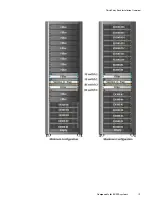
Page 13: ...Third Party Rack Installation Overview Components for EX300 systems 13 ...

Page 14: ...Third Party Rack Installation Overview 14 EX300 Third Party Rack Installation Guide ...

Page 15: ...R 2 Rail Installation This chapter describes how to install the rails into the customer racks l Optional Dell EMC PDU rail assembly installation 16 l Installing rails for an EX300 rack 20 Rail Installation 15 ...

Page 16: ...ocation The Dell EMC 2U PDU component is installed below the back end switches A 42U or greater rack is required if a Dell EMC 2U PDU is provided and there will be 16 servers added to the rack or if you are planning to expand to 16 servers at some future time If installing the Dell EMC PDU be sure to install the PDU l With a 1U empty space between the bottom and back end switch and the PDU l In th...

Page 17: ...Figure 1 PDU component location Rail Installation Dell EMC PDU rail and component location 17 ...

Page 18: ...r screws two each side in the lower two holes of the highest U 4 Extend the rail to the rear channel and loosely install four screws adjacent to each of the alignment pins This leaves the two center holes open Installing the EMC PDU support assembly Procedure 1 From the rear of the system insert the left side of the PDU support assembly onto the PDU rails and gently slide it 3 4 onto the rail 2 Fr...

Page 19: ...o the center rail screw holes Then using a Phillips head 4 or less screwdriver use the eight 8 silver securing screws 4 on each side to attach the two halves together 4 Push the assembly completely into the rack and secure using four 4 black securing screws 2 on each side Figure 4 Completing EMC PDU support assembly installation 3 3 Front Front Rear Rear 1 2 3 4 1 2 1 Rail Installation Installing ...

Page 20: ...rder 1 Install all rails for EX300 nodes 2 Secure all rails for EX300 nodes to the rack 3 Install all rails for front and back end switches 4 Sucure all rails for front and back end switches to the rack Do not install any nodes or switches until all rails are installed in the rack Install rails for EX300 nodes Install all EX300 rails before you secure them to the rack The rails are labeled left an...

Page 21: ...ign with the holes on the rear cabinet flanges 4 Push the rail straight toward the rear of the rack until the latch locks in place Figure 6 Installing the rear end of the rail 5 For the front end piece rotate the latch outward and pull the rail forward until the pins slide into the flange and release the latch to secure the rail in place Figure 7 Installing the front end of the rail 6 Repeat the p...

Page 22: ...spaces 2 Insert and tighten the two screws using the Phillips 2 screwdriver Figure 8 Installing screws Install rails for switches After you install all node rails install the rails for the switches Dell EMC S5148F switches for ECS are installed with the Dell EMC Gen 3 14 sliding rail system The Dell EMC S5148F switches are required for the two back end switches The customer has the option of using...

Page 23: ...rack There is label on the rail that reads INSTALL DEVICE THIS END You will be sliding the switch into the rack from the front so that label should be at the front of the rack a Align the support screws with the correct location on the rack b Press down on the label that reads PUSH to open the rail clip c Guide the support screws at the end of the rail into the rack holes until the clip snaps to t...

Page 24: ... end of the rail clips to the back of the rack 4 Repeat these steps to install the second rail on the other side of the rack 5 Repeat until all switch rails are installed Rail Installation 24 EX300 Third Party Rack Installation Guide ...

Page 25: ...d switch installation This chapter describes how to install 2U PDUs nodes and switches into the customer racks l Optional PDU component installation 26 l Installing nodes and switches 27 PDU node and switch installation 25 ...

Page 26: ...S you will need to unpack and install it Single phase power connectors Systems with single phase power components include an integrated PDU component with three AC Main connectors P1 P2 P3 for each power zone PDU node and switch installation 26 EX300 Third Party Rack Installation Guide ...

Page 27: ...e weight of the PDU is supported 2 If installing a single phase PDU a CAUTION During the cabling procedure in the next step make sure the PDU does not slide out so far that its weight is not supported b Push the PDU towards the front of the rack until it snaps into position You should hear an audible click when the PDU is secured 3 Repeat the previous steps for the RIGHT PDU zone A Figure 9 Insert...

Page 28: ...the front rail It is recommended to use the default 28 mounting points for the inner rails Once you have installed the switches you can install the 1U bezels as described in the following section Installing the 1U bezel Procedure 1 Attach the inner rails to the switch Make sure the ears at the end of the rails are pointing outward and are installed at the back end of the switch a Insert the mounti...

Page 29: ... 3 Slide the switch into the rack until you can secure the back ears of the rail to the rack with the two black screws on the rail Secure the rail to the rack by tightening the black thumb screw on each rail PDU node and switch installation Switch installation 29 ...

Page 30: ...el Procedure 1 Locate the left 1U bezel pod only the left pods are marked Line up the captive mounting screw with the mounting hole in the rails PDU node and switch installation 30 EX300 Third Party Rack Installation Guide ...

Page 31: ... using the captive screw 3 Repeat for the right pod 4 Angle the 1U bezel and fit the right side of the 1U bezel into the right pod 1 5 Depress bezel latch and slide the left side of the 1U bezel into the left pod until it snaps into place 2 PDU node and switch installation Switch installation 31 ...

Page 32: ...e node requires a lift and at least 2 people to complete the operation Procedure 1 At front of the cabinet pull the inner slide rails out of the rack until they lock into place Figure 10 Extend rails from the cabinet 2 Locate the rear rail standoff on each side of the system Position the system above the rails and lower the rear rail standoffs into the rear J slots on the slide assemblies 3 Rotate...

Page 33: ... release lock tabs forward on both rails and slide the system into the cabinet The slam latches will engage to secure the system in the cabinet Note Ensure that the inner rail slides completely into the middle rail The middle rail locks if the inner rail is not fully engaged PDU node and switch installation Install the nodes 33 ...

Page 34: ...tus LEDs such as an SPS The main difference is that the pods for the LEDs are attached using one screw and the non LED pods use two screws Procedure 1 Locate the left 2U bezel pod only the left pods are marked Line up the captive mounting screw s one screw for pods used with status LEDs and two screws used for pods for non LED devices with the mounting holes in the rails PDU node and switch instal...

Page 35: ...unting screw depress the mounting hold access door so that it open upwards and attach the pod to the rail using the captive screw 3 Repeat for the right pod 4 Angle the 2U bezel and fit the right side of the 2U bezel into the right pod 1 PDU node and switch installation Install the nodes 35 ...

Page 36: ...connect cables make sure you label both ends of every cable to clearly identify the node or switch to which it should connect Place the labels at least 14 inches from the switch end of the cable to make sure the label is clearly visible after all cables are connected Place the label 4 inches between the other two labels from the connector on the node end If you have leftover labels after you finis...

Page 37: ... This chapter describes how to configure the switches and power the nodes on to bring the ECS system online l Bring the ECS system online 38 l Upload the switch configuration files 38 l Power on the nodes 41 Bring the system online 37 ...

Page 38: ...ches are powered on There are no power buttons for the switches The switches are turned on once they have been plugged in and connected to a power source A solid green color on the Power LED and System LED indicates the switch is on and operating normally Power LED System LED Connect to the switch serial port This section describes how to connect your service laptop to a serial port on an S5148 sw...

Page 39: ...8 data bits l no hardware flow control Alternatively if not using PuTTY the generic serial settings are l Data rate 115200 l Data bits 8 l Parity none l Stop bits 1 l Hardware flow control none 5 Click Open to connect 6 Press Enter to display the login prompt Load the switch configuration files 1 Connect to the switch serial port as described above 2 Log into the switch with the Dell OS10 default ...

Page 40: ...ll overwrite the existing startup xml file OS10 copy config ECSv3 fox dell s5148 v1 0 xml config startup xml 5 Reload the switch to load in the configuration OS10 reload 6 If there is any messaging to save any existing configuration type n System configuration has been modified Save yes no n 7 When asked to reboot the system type y Proceed to reboot the system confirm yes no y 8 Once the switch ha...

Page 41: ...er on the nodes after you have configured the switches Figure 15 EX300 node power button and LED light Power button LED light Turn the power button on The LED displays a solid blue line when the node is powered on Bring the system online Power on the nodes 41 ...

Page 42: ...Bring the system online 42 EX300 Third Party Rack Installation Guide ...

Page 43: ...his chapter provides details on how to return shipping or packing materials l Preparing materials for pickup 44 l Returning material from U S and Canada sites 44 l Returning material from international sites 44 Return shipping or packing materials 43 ...

Page 44: ...tent RMA Process 3 Search for the RMA Pickup Request Form 4 Complete the form and then send it to the appropriate RMA content listed at the bottom of the form Returning material from international sites When returning material RMA from sites outside of the U S and Canada send an email to RMA sales Procedure l Send an email to RMA sales with details specific to the materials that you intend to retu...

Page 45: ...APPENDIX A Mechanical lift This section contains the following information l Working with the portable lift 46 Mechanical lift 45 ...

Page 46: ... The lower mast configuration is rated for 400 pounds and is for raising or lowering objects 28U 49 inches or less above the floor The dual mast configuration is rated well under 200 pounds and is for raising objects more than 28U 49 inches above the floor l For installations at or below 49 inches you must use the lower mast configuration l For installations above 49 inches use the Voyager convers...

Page 47: ...trument must be lifted Option Description For installations at or below 49 inches 28U above floor level You must use the lower single mast configuration Refer to Using the lift on an enclosure less than 49 above the floor For installations 49 inches 28U above floor level Use the Voyager conversion kit and a support table kit with the lower single mast configuration See Using the lift on an enclosu...

Page 48: ...ided within the kit to reconfigure the lift Figure 17 Reconfiguring the portable lift with the Voyager conversion kit CL5422 1 2 Adjusting the arms for a frontal lift If you plan to use the mechanical lift directly in front of the cabinet adjust the lift arm tray width to just under 17 inches apart to ensure that the arms will stay under the chassis Figure 18 on page 49 shows an example of adjusti...

Page 49: ...e pin and pulling the pin out It may be necessary to wiggle the pin with the plunger pressed to free it from its mounting hole b Hold the arm with one hand while pressing the plunger on the top ball lock pin and pulling the pin out with the other hand It may be necessary to wiggle the pin with the plunger pressed to free it from its mounting hole The arm will be free of the lift chassis c Remove t...

Page 50: ...t place the cordless drill over the hex fitting and use the drill to raise or lower the arm to the required height 4 Adjust the arm of the portable lift to the approximate height of the enclosure you intend to move 5 Attach the tray to the lift arm 6 Lock all four casters by pressing down on the locking tab so the lift will not roll as the instrument is placed onto it Figure 20 Locking the Casters...

Page 51: ...hanism Pull the ratchet handle down to tighten the securing strap around the lift and the enclosure Figure 22 Tightening the Straps 1 2 CL5429 c Make sure the enclosure is securely strapped to the lift before moving Lower the lift to its lowest point of travel This allows the enclosure to be moved with minimal danger of tipping over Mechanical lift Using lift on an enclosure 49 or less above the f...

Page 52: ...ded Figure 24 Removing the Straps 1 CL5430 2 Using the lift on an Enclosure more than 49 above the floor If you are using an Alum A Lift to work on a enclosure that is more than 49 inches above the floor you must use the Voyager conversion kit and a support table with the lower mast configuration Procedure 1 If necessary orient the arm to the high lift position as follows Mechanical lift 52 EX300 ...

Page 53: ...he arm with the adaptor attached will be free of the lift chassis c Remove the arm from the lift and reverse it to achieve the desired orientation d Attach the arm to the lift chassis by aligning the mounting holes pressing the plunger and inserting the ball lock pins into the holes Insert the top pin first 2 Remove the rotating handle if necessary by loosening the set screw and pulling the handle...

Page 54: ...e required height With the enclosure extended from the rack on the rails pull the enclosure from the rails and onto the lift Secure the enclosure to the portable lift using the securing straps as follows Figure 27 Removing an enclosure from rails more than 49 above the floor CL5431 a Place the securing strap around the lift and the enclosure Mechanical lift 54 EX300 Third Party Rack Installation G...

Page 55: ... enclosure is supported by the arm lower the arm to the lowest point that still permits travel This allows the enclosure to be moved with minimal danger of tipping over 6 Unlock the casters by lifting up on the locking tabs and move the enclosure as required Figure 29 Unlocking the Casters CL5424 7 Move the enclosure to the support table Use the drill to raise or lower the enclosure above the supp...

Page 56: ...e retaining key and pull the ratchet handle upwards as needed Figure 31 Removing the Straps 1 CL5430 2 9 To move the enclosure to the deck or to a shipping pallet the lift arm must be in the lower mast position Refer to Mechanical lift 56 EX300 Third Party Rack Installation Guide ...

Reviews: