background image

Dell EMC VMware Cloud Foundation for 
PowerEdge MX7000

Deployment Guide

Summary of Contents for PowerEdge MX7000

Page 1: ...Dell EMC VMware Cloud Foundation for PowerEdge MX7000 Deployment Guide ...

Page 2: ...amage to hardware or loss of data and tells you how to avoid the problem WARNING A WARNING indicates a potential for property damage personal injury or death 2019 Dell Inc or its subsidiaries All rights reserved Dell EMC and other trademarks are trademarks of Dell Inc or its subsidiaries Other trademarks may be trademarks of their respective owners 2019 05 Rev A01 ...

Page 3: ...4 Front view of the PowerEdge MX7000 chassis 14 Back view of the PowerEdge MX7000 chassis 15 Logical view of the PowerEdge MX7000 chassis 15 Dell EMC PowerEdge MX740c compute sled 16 Dell EMC PowerEdge MX5016s storage sled 17 Dell EMC PowerEdge MX9002m management module 18 Dell EMC Networking MX9116n Fabric Switching Engine 19 Dell EMC Networking MX7116n Fabric Expander Module 19 Dell EMC Networki...

Page 4: ...l infrastructure layer 36 Host names and IP addresses for the operations management layer 37 8 Networking requirements 38 VMware Cloud Foundation networking 38 Network configuration options 39 Network connectivity 39 VLAN and subnets for networking configuration 45 9 Manual switch configuration 46 Switch operating mode 46 VLANs and subnets for manual switch configuration 46 Uplink and VLTi ports 4...

Page 5: ...ttings using DCUI 69 Configure ESXi settings using web interface 70 13 Cloud Builder OVA deployment 73 Deploy OVA 73 14 Running Cloud Builder 76 Prerequisites 76 Launch Cloud Builder web interface 76 Cloud Builder Deployment Parameter Sheet 77 Cloud Builder parameters 77 Management Workload tab 78 Users and Groups tab 78 Hosts and Networks tab 78 Deploy Parameters tab 78 Configure Cloud Builder va...

Page 6: ...on of buttons cables and components in the hardware Functional knowledge of the items in the Dell EMC owner s manuals for the products being used VMware products and the components or features of VMware vSphere Data center infrastructure best practices in the areas of server storage networking and environmental considerations such as power and cooling The scope of this document excludes existing i...

Page 7: ...rprise Modular Edition that provides the features of OpenMange Enterprise systems management within the PowerEdge MX chassis It includes a unified interface console for managing compute storage and networking Three I O networking fabrics two general purpose and one storage specific each with redundant modules Multichassis networking up to 10 chassis Single management point for compute storage and ...

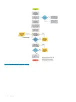
Page 8: ...Figure 1 Cloud Foundation deployment workflow 8 Overview ...

Page 9: ...ded to this management host An NTP time server is installed on the management VLAN and a DHCP server on the VXLAN VLAN Figure 2 Management host in an existing vSphere environment Connectivity The Cloud Builder VM must be able to communicate with the hosts that become the Cloud Foundation management cluster In this example the new cluster hosts were given IP addresses on the 172 16 11 0 24 subnet a...

Page 10: ...VXLAN VTEPs A Virtual Tunnel End Point VTEP is an NSX software based endpoint of a VXLAN connection that communicates over their IP addresses and are on the same Layer 2 L2 network A large IP address pool is required for every host connection on the VXLAN network one address per NIC per host NOTE Software based VTEPs could transition to hardware based VTEPs with the launch of new features included...

Page 11: ...rives in a host is cleanly divisible by the number of cache drives that is the result is a whole number Table 1 Hardware components Manufacturer Model Description Specifications Dell EMC PowerEdge MX7000 Chassis Dell EMC PowerEdge MX740c Compute sled 2x Xeon Gold processor 256 GB RAM Cache drives Dell EMC PowerEdge MX5016s Storage sled 12 Gbps SAS Capacity drives Dell EMC PowerEdge MX5000s SAS Fab...

Page 12: ...box enter the model of the server for example PowerEdge MX740c 4 Click Update and View Results 5 In the Server Device and Model Information section select the required model NOTE Only the minimum supported versions of server BIOS are displayed The BIOS and the compatible ESXi versions for the selected model are displayed View driver and firmware versions for Network Interface Card 1 Open VMware Co...

Page 13: ...P 06 11675023 IOM Switch OS 10 4 0E R4S 10 4 0E R4S 347 VMware Cloud Foundation includes the following 3 7 0 12696155 Cloud Builder VM 2 0 12696155 VMware vCenter Server Appliance 6 7 U1b 11726888 VMware NSX Data Center for vSphere 6 4 4 11197766 VMware vRealize Log Insight 4 7 9983377 SDDC Manager 3 7 0 12696155 Firmware and drivers The following table lists the firmware and ESXi driver versions ...

Page 14: ...ess transformations Key features of PowerEdge MX7000 include 7U modular enclosure with eight slots that can accommodate 2S single or four 4S double width compute sleds and 12 Gb s single width storage sleds 25 Gb Ethernet 12 Gb SAS and 32 Gb Fiber channel I O options Three I O network fabrics two for general use and one for storage only each with redundant modules Multichassis networking up to 10 ...

Page 15: ...et switches installed in fabric slots A1 and A2 Two Dell EMC PowerEdge MX9002m management modules that are installed in management slots MM1 and MM2 Two Dell EMC PowerEdge MX5000s SAS fabric switch modules that are installed in fabric slots C1 and C2 Empty or available fabric slots B1 and B2 Figure 4 PowerEdge MX7000 chassis rear view Logical view of the PowerEdge MX7000 chassis PowerEdge MX7000 s...

Page 16: ...dation for collaborative workloads The PowerEdge MX7000 chassis supports up to eight PowerEdge MX740c sleds if no other sleds are used such as PowerEdge MX5016s storage sleds 24 DIMM slots of DDR4 memory Up to six SAS or SATA SSD or hard drive and NVMe PCIe SSDs Boot device options such as BOSS S1 Two PCIe mezzanine card slots for connecting to network Fabric A and B One PCIe mini mezzanine card s...

Page 17: ... PowerEdge MX840c compute sleds can share drives with the PowerEdge MX5016s sled using the PowerEdge MX5000s SAS module Internal server drives may be combined with up to seven PowerEdge MX5016s sleds in one chassis for extensive scalability The PowerEdge MX7000 chassis supports up to seven PowerEdge MX5016s storage sleds NOTE SATA and NVMe devices are not supported in the PowerEdge MX5016s storage...

Page 18: ...ternal 1G BaseT Ethernet ports are provided to enable management connectivity and to connect more PowerEdge MX7000 chassis into a single logical chassis The PowerEdge MX7000 chassis supports two PowerEdge MX9002m management modules for redundancy Figure 8 PowerEdge MX9002 management module 1 Handle release 2 Gigabit Ethernet port 1 3 Gigabit Ethernet port 2 4 ID button and health status LED 5 Powe...

Page 19: ...r up to nine more PowerEdge MX7000 chassis using the MX7116n Fabric Expander Module The QSFP28 DD ports also provide capacity for extra uplinks VLTi links and connections to rack servers at 10 GbE or 25 GbE using breakout cables The PowerEdge MX7000 chassis supports up to four MX9116n FSEs in Fabric A or B or both Figure 9 MX9116n FSE 1 Express service tag 2 Storage USB port 3 Micro B USB console ...

Page 20: ...28 ports Four 10 GbE RJ45 BASE T ports The ports can be used to provide a combination of network uplinks VLT interconnects VLTi or for FCoE connectivity The MX5108n switch supports FCoE Initialization Protocol FIP Snooping Bridge FSB mode but does not support NPG or direct attach FC capabilities The PowerEdge MX7000 chassis supports up to four MX5106n Ethernet switches in Fabric A or Fabric B or b...

Page 21: ... Controller PERC in the mini mezzanine PCIe slot The PowerEdge MX5000s switches are deployed as redundant pairs to offer multiple SAS paths to the individual SAS disk drives The PowerEdge MX7000 chassis supports redundant PowerEdge MX5000s in Fabric C Figure 12 Dell EMC PowerEdge MX5000s storage sled 1 Express service tag 2 Module insertion or removal latch 3 Power and indicator LEDs 4 Six SAS por...

Page 22: ...s impacted by the number of PowerEdge MX7000 chassis in use but no other changes are made in the environment Topics Configuration options Cabling Configuration options Option 1 single PowerEdge MX7000 enclosure One Dell EMC PowerEdge MX7000 enclosure Four Dell EMC PowerEdge MX740c compute sleds Two Dell EMC Networking MX5108n Ethernet switches Figure 13 Single PowerEdge MX7000 enclosure Option 2 s...

Page 23: ...res Two Dell EMC PowerEdge MX7000 enclosures Four Dell EMC PowerEdge MX740c compute sleds Four Dell EMC Networking MX5108n Ethernet switches Figure 15 Two PowerEdge MX7000 enclosures Option 4 two PowerEdge MX7000 with MX5016s storage sled Two Dell EMC PowerEdge MX7000 enclosures Physical layout 23 ...

Page 24: ...two PowerEdge MX7000 enclosures using Fabric Switching Engine Two or more up to a maximum of 10 Dell EMC PowerEdge MX7000 enclosures Four Dell EMC PowerEdge MX740c compute sleds Two Dell EMC Networking MX9116n Fabric Switching Engines Two Dell EMC Networking MX7116n Fabric Expansion Modules Plus two MX7116n modules for each additional chassis Four Dell EMC PowerEdge MX5000s SAS IO Modules only if ...

Page 25: ...d and the PowerEdge MX5000s SAS IOM has no impact on external cabling Cabling for a single PowerEdge MX7000 enclosure configuration The following figure shows the external cabling for a single PowerEdge MX7000 enclosure configuration The Customer Network Link Aggregation is shown here as an example as the upper layer connection is not specified but it must use an LACP enabled Link Aggregation LAG ...

Page 26: ...l cabling for a multiple PowerEdge MX7000 enclosure configuration The Customer Network Link Aggregation is shown as an example as the upper layer connection is not specified except that it must use an LACP enabled Link Aggregation LAG You can add more enclosures that connect back to the upper level devices in the infrastructure 26 Physical layout ...

Page 27: ...Figure 19 Dual PowerEdge MX7000 enclosure configuration Physical layout 27 ...

Page 28: ...work Link Aggregation is shown as an example as the upper layer connection is not specified except that it must use an LACP enabled Link Aggregation LAG You can add more enclosures up to a maximum of 10 that connect back to the upper level devices in the infrastructure Additional PowerEdge MX7000 enclosures require only two MX7116n Fabric Expansion Modules whose ports appear as additional ports on...

Page 29: ...Figure 20 MX9002m Management module cabling Physical layout 29 ...

Page 30: ...Figure 21 Connectivity between FSE modules and FEM modules 30 Physical layout ...

Page 31: ...Figure 22 Uplinks to customer network environment Physical layout 31 ...

Page 32: ...ion and for the deployment of other optional components such as vRealize Operations or vRealize Automation The following table lists the required and optional external services and dependencies Table 4 Required and optional external services and dependencies Service Purpose Active Directory AD Optional Provides authentication and authorization NOTE AD is required if you are deploying vRealize Auto...

Page 33: ...are contained within the Cloud Foundation solution which includes servers virtual machines and any virtual IPs that are used For more information on the components that are required for DNS resolution before starting a Cloud Foundation deployment see Host names and IP addresses Ensure that both forward and reverse DNS resolutions are functional for each component before deploying Cloud Foundation ...

Page 34: ... a process called host commissioning During this process the hosts are associated with an existing network pool When the host is provisioned during the create VI workload domain add cluster or add host workflow it automatically configures the VMkernel ports and allocates IP addresses for vMotion vSAN and NFS from the network pool the host was associated with You can expand the included IP address ...

Page 35: ...solvable through forward and reverse lookups The required hostnames and IP addresses are categorized as follows External services services that are external to the Cloud Foundation solution and are required for proper operation Virtual infrastructure layer components that provide for the basic foundation of the Cloud Foundation solution Operations management layer components used for day to day ma...

Page 36: ...lation After the initial deployment additional workload domains are created and you must define components specific to each additional workload domain Planning ahead for the initial deployment and the workload domains to be created avoids delays in deployment The following table provides an example of the information for the virtual infrastructure layer using the standard deployment model with a s...

Page 37: ...e Lifecycle Manager vRSLCM and an edge device used for load balancing within the management domain These two components are shared between vRealize Operations and vRealize Automation and are automatically installed if either product is deployed NOTE You must define the hostnames and IP addresses for the vRealize Operations components to be installed within the solution and the shared components if...

Page 38: ...ed for all connectivity within the management stack There is also an IP network that connects back to an external network Each of these networks is propagated to the Cloud Foundation stack using tagged VLANs Using tagged VLANs enables mapping of port groups to VLANs allowing access to resources as needed All these networks are routable to and from each other The routing task is executed at some la...

Page 39: ...Networking MX5108n switch modules the switches are installed in Fabric A of the PowerEdge MX7000 enclosure Each modular switch has eight internal ports with one port being connected to each compute sled Two modules provide a redundant A1 and A2 connection to each of the PowerEdge MX740c compute sleds The connection between the compute sleds and the MX modular switches do not use any kind of link a...

Page 40: ...e PowerEdge MX7000 chassis network connectivity using MX5108n Ethernet switches When deploying multiple PowerEdge MX7000 chassis the network connectivity is as shown in the following figures 40 Networking requirements ...

Page 41: ...Figure 24 Multiple PowerEdge MX7000 chassis network connectivity using MX5108n Ethernet switches Networking requirements 41 ...

Page 42: ...Figure 25 MX9002m Management Module cabling 42 Networking requirements ...

Page 43: ...Figure 26 Connectivity between FSE modules and FEM modules Networking requirements 43 ...

Page 44: ...Figure 27 Uplinks to customer network environment 44 Networking requirements ...

Page 45: ...gured for jumbo frames VLAN and subnets for networking configuration The following table shows the VLAN and networking data that are used for the Cloud Foundation deployment In our example private addresses are used for Management vSAN vMotion and VXLAN networks However this is not mandatory Table 10 VLAN and networking data used for the Cloud Foundation deployment Name VLAN ID Subnet Mask Default...

Page 46: ...bnets for manual switch configuration Create the VLANs required for Cloud Foundation by using the following commands MX7K IOM A2 MX7K IOM A2 config MX7K IOM A2 config interface vlan 1611 MX7K IOM A2 conf if vl 1611 description Management MX7K IOM A2 conf if vl 1611 mtu 9216 MX7K IOM A2 conf if vl 1611 exit MX7K IOM A2 config interface vlan 1612 MX7K IOM A2 conf if vl 1612 description VSAN MX7K IOM...

Page 47: ... VLT interconnect VLTi between the two Dell EMC MX5108n switches is a port group that is generated by configuring a VLT domain and specifying the discovery interfaces When using the MX9116n FSEs and MX7116n FEMs the uplink ports will be ports 40 and 42 Before you start verify that the mode for ports 1 1 9 and 1 1 10 on the back of the MX5108n switches are set to 40 G MX7K IOM A2 show interface sta...

Page 48: ... domain on each MX5108n switch It contains the exact same VLT domain on each switch In this case create a VLT domain 101 on each switch The backup destination for the A1 MX5108n switch is the IPv4 address of the A2 MX5108n switch Similarly the backup destination for the A2 MX5108n switch is the IPv4 address of the A1 MX5108n switch Create a unique MAC address to make identifying and troubleshootin...

Page 49: ...0g 1x If the running configuration shows that the port is mapped to 10g or 40g you can remap it by running the following command MX7K IOM A2 MX7K IOM A2 configure terminal MX7K IOM A2 config interface breakout 1 1 11 map 100g 1x MX7K IOM A2 config A VLT link aggregation is created by creating a VLT port channel on each of the MX5108n switches First create the uplink VLT port channel on both MX5108...

Page 50: ... are now configured with the minimum required settings to support the deployment of Cloud Foundation Run the running config command to verify the configuration The configuration should look like Version 10 4 0E R3S Last configuration change at Mar 13 15 38 44 2019 snmp server contact http www dellemc com support softwarecontacts hostname MX7K IOM A2 interface breakout 1 1 10 map 40g 1x interface b...

Page 51: ...ff switchport mode trunk switchport access vlan 1 switchport trunk allowed vlan 96 1611 1614 2711 2712 mtu 9216 interface ethernet1 1 3 no shutdown fec off switchport mode trunk switchport access vlan 1 switchport trunk allowed vlan 96 1611 1614 2711 2712 mtu 9216 interface ethernet1 1 4 no shutdown fec off switchport mode trunk switchport access vlan 1 switchport trunk allowed vlan 96 1611 1614 2...

Page 52: ...Ti no shutdown no switchport mtu 9216 interface ethernet1 1 11 no shutdown channel group 1 mode active no switchport mtu 9216 interface ethernet1 1 12 no shutdown switchport access vlan 1 interface ethernet1 1 13 no shutdown switchport access vlan 1 interface ethernet1 1 14 no shutdown switchport access vlan 1 interface ethernet1 1 15 no shutdown switchport access vlan 1 interface mgmt1 1 1 no shu...

Page 53: ...map type qos class trust class map type qos CM1 match vlan 1 vlt domain 101 backup destination 100 71 96 121 discovery interface ethernet1 1 9 1 1 10 1 vlt mac 00 11 22 33 55 66 Manual switch configuration 53 ...

Page 54: ...deploy a SmartFabric complete the following steps using the OME Modular console 1 Create chassis groups 2 Create the networks to be used in the fabric 3 Select IOMs and create the fabric that are based on the required physical topology 4 Create uplinks from the fabric to the existing network and assign networks to those uplinks 5 Deploy the appropriate server templates to the compute sleds Topics ...

Page 55: ...agate to each chassis that is added to the group and then click Next The Add Members page displays the chassis that can be added as members to the group The lead chassis is not listed here 5 Select the chassis to be added and then click Add Chassis The selected chassis moves to the Current Members list 6 Click Finish A chassis group is created and the selected members are added 7 To view the list ...

Page 56: ...llowing steps Steps 1 Open the OME M console 2 From the Configuration menu click Networks 3 In the Network pane click Define 4 In the Define Network window complete the following a Enter the name of the network b Optionally enter the description in the DESCRIPTION box c Enter the value 1611 in the VLAN ID box d From the Network Type list select General Purpose Bronze e Click Finish 5 Repeat steps ...

Page 57: ...5108n Ethernet switching IOMs About this task To create a SmartFabric using the OME M console perform the following steps Steps 1 Open the OME M console 2 From the Devices menu click Fabric 3 In the Fabric pane click Add Fabric 4 In the Create Fabric window complete the following a Enter SmartFabric in the Fabric Name box b Optionally enter the description in the Description box c Click Next 5 Bas...

Page 58: ...Fabric using MX9116n Fabric Switching Engine IOMs 6 From the Chassis X list select the first PowerEdge MX7000 chassis containing an MX9116n FSE 7 From the Switch A list select Slot IOM A1 8 From the Switch B list select Slot IOM A2 9 Click Next 10 On the Summary page verify the proposed configuration and then click Finish The fabric displays a health error which is resolved in the next section by ...

Page 59: ...lick Fabric and then perform the following steps a Click the fabric that was created b Click Topology The selected topology image is displayed as shown in the following figure Figure 34 Topology of the SmartFabric using MX9116n Fabric Switching Engine IOMs SmartFabric creates the uplink object and the status for the fabric changes to OK Configure jumbo frames About this task Cloud Foundation requi...

Page 60: ...ane click Select Device e In the Select Devices window select Sled 1 from Chassis 1 and then click Finish f From the Elements to Clone list select the following options 1 iDRAC 2 System 3 NIC g Click Finish A job starts and the new server template is displayed on the list When the job completes the status is displayed as Completed Successfully Next step After the job completes associate the VLANs ...

Page 61: ...oy pane select the MX740c with Intel mezzanine server template and then click Deploy Template 2 In the Deploy Template window complete the following steps a Click Select to choose the slots or compute sleds to deploy the template to b Select Do not forcefully reboot the host OS c Click Next d Select Run Now e Click Finish The interfaces on the switches are updated automatically SmartFabric configu...

Page 62: ... pre requisites for this section Prerequisites The following items are required to map PowerEdge MX5016s storage sled drives OME M and iDRAC IP addresses or FQDNs OME M and iDRAC credentials Storage sleds deployed which includes SAS drives specified in Validated components section Compute sleds deployed Map drives to compute sleds Drives in PowerEdge MX5016s storage sled can be mapped at the enclo...

Page 63: ... 35 OME Modular web interface Devices and storage page 5 Select Edit Assignments 6 Select the check boxes for slots 0 1 2 and 3 and then click Assign Drive to Slot Map PowerEdge MX5016s storage sled drives 63 ...

Page 64: ...web interface Edit assignment page 7 In the Assign Hard Drive to Compute window select Slot 1 Sled 1 and then click Assign Assignment for slots 0 3 is set to compute Slot 1 Sled 1 64 Map PowerEdge MX5016s storage sled drives ...

Page 65: ...t steps 4 7 to map the remaining drives as shown in the following table Table 11 Mapping of PowerEdge MX5016s drive to storage sled Chassis PowerEdge MX5016s Drives Assign to Sled Slot 1 4 7 2 2 0 3 1 2 4 7 2 Map PowerEdge MX5016s storage sled drives 65 ...

Page 66: ...lar and iDRAC credentials iDRAC Enterprise license that is applied on all nodes Dell EMC customized ESXi image Host names Management VLAN ID IP address information Credentials for vSphere Hostnames added to DNS server Installation of ESXi Complete the following steps on each physical compute node targeted for Cloud Foundation deployment before moving on to the next section Connect to iDRAC and boo...

Page 67: ...ng this step may be necessary due to browser pop up blocker Figure 38 Virtual console preview 6 The mapping screen for the virtual media is displayed on the Virtual Media menu 7 In the Map CD DVD section click Choose File 8 Browse and select the required Dell EMC customized ESXi image ISO image file 9 Click Map Device and then click Close Deploy ESXi to cluster nodes 67 ...

Page 68: ...ng VMware ESXi you must connect to the iDRAC devices and boot into the ESXi installer For more information see Connect to iDRAC and boot installation media Steps 1 In the Welcome to ESXi Installation window press Enter 2 Review the End User License Agreement EULA and then press F11 to accept and continue 3 On the Select a Disk to Install or Upgrade page select the DELLBOSS VD device and then press...

Page 69: ... User Interface DCUI is a menu based interface that is accessed from the host console and used to configure ESXi running on vSphere hosts Steps 1 After the server reboots and fully loads ESXi press F2 to log in to the DCUI 2 Enter the credentials that were created during the ESXi installation and then press Enter 3 From the System Customization menu select Configure Management Network 4 From the V...

Page 70: ...lect Troubleshooting Options Enable ESXi Shell and then select Enable SSH required during validation and deployment phases to enable the ESXi shell 15 Press Esc to return to the main menu Configure ESXi settings using web interface Prerequisite Before configuring ESXi settings using web interface you must configure the ESXi settings using DCUI For more information see Configure ESXi settings using...

Page 71: ...p 6 In the Navigator pane click Manage to set up the NTP 7 In the right pane click Time Date 8 Click Edit Settings and then select Use Network Time Protocol enable NTP client 9 From the NTP Service Startup Policy list select Start and stop with host 10 In the NTP Servers box enter the NTP server IP addresses NOTE If multiple IP addresses are provided separate the IP addresses with commas 11 Click ...

Page 72: ...b interface Manage pane Next step Repeat all the steps for each host targeted for Cloud Foundation management domain deployment Validate that each ESXi host can access the NTP servers by establishing an SSH connection to each host and executing the ntpq p command A refid value of INIT indicates that your host is not obtaining time from your specified time source 72 Deploy ESXi to cluster nodes ...

Page 73: ...Foundation Management VLAN on which the Cloud Builder VM resides All prior sections are reviewed and any listed steps completed NOTE There are multiple ways to deploy an OVA This example involves deploying the OVA from vCenter For best results in terms of speed and reliability of OVA deployment it is recommended to copy the OVA file to the virtual environment For example on a VM running on the Clo...

Page 74: ...ord network 1 IP address and subnet mask default gateway hostname DNS and NTP resources in the appropriate fields and then click Next CAUTION You must adhere to the following password rules that are listed on the screen Noncompliant passwords cause an unrecoverable error when attempting to access and use the Cloud Builder VM in the next section of the document The password rules vary for different...

Page 75: ...e 11 Review the Ready to Complete final configuration page and then click Finish 12 In the Recent Tasks pane check the OVA deployment status When the OVA deployment is complete turn on the Cloud Builder VM Cloud Builder OVA deployment 75 ...

Page 76: ...loyed to an available ESXi host outside of the Cloud Foundation target nodes with network access to the Cloud Foundation Management VLAN Target hardware certified on VMware Compatibility Guide VCG with appropriate firmware versions are specified in the Validated components section Clean install of ESXi on each target server node with SSH NTP DNS enabled and configured Physical switches configured ...

Page 77: ...covers the process to deploy Cloud Foundation using a spreadsheet for example xlsx format However Cloud Builder also supports the use of a json file for uploading deployment parameters The latter is outside the scope of this document This worksheet is incorporated into the Cloud Builder VM and specific version of Cloud Foundation that is deployed Save the worksheet to a safe location and edit the ...

Page 78: ...tworks Host names that you enter in the Management Domain ESXi Hosts section are also auto populated in the ESXi Host column of the ESXi Host Security Thumbprint section Deploy Parameters tab The Deploy Parameters tab contains all the IP addresses and hostnames that must be added to DNS All the hostnames must be configured for forward and reverse lookups Test all the hostnames before attempting va...

Page 79: ...or more However if there are issues such as the DNS server being down or if you provided a wrong IP address validation may take longer NOTE On the Validation Report page you can access the information about previous validation attempts Each validation attempt is tracked with an entry that is designated by the date and time of execution 3 If the validation fails expand the failed line item and revi...

Page 80: ... is necessary to resolve the root cause issue wipe the Cloud Foundation target servers including all disk partitions and then restart from the Deploy ESXi to cluster nodes section 3 The SDDC bring up process is completed when the Cloud Builder reports that the SDDC has been successfully created When the SDDC bring up process is complete this indicates that the Cloud Foundation is successfully depl...

Page 81: ... Do not use the DNS domain that was used for the Cloud Foundation deployment Customer Experience Improvement Program Join Customer Experience Improvement Program CEIP when prompted CEIP provides statistical data to SDDC Manager allowing for improved performance and troubleshooting The following figure shows a sample SDDC Manager dashboard In this example the host usage is yellow because the manage...

Page 82: ...steps Steps 1 On the Hosts and Clusters tab select the management cluster 2 On the Configure tab click Disk Management In the Disk Groups section you should see each of your hosts in the management cluster and the disk groups NOTE In this example there are two disk groups on each server with three disks in each group Figure 52 vSAN Disk Groups NSX Manager About this task To verify that NSX Manager...

Page 83: ... the vCenter interface select the Home menu 2 Select Network and Security from the drop down list The NSX dashboard is displayed as shown in the following figure Figure 53 NSX dashboard Post install validation 83 ...

Reviews: