background image


Dell 1815dn 

Service Manual


27 Mar 2006


Summary of Contents for 1815 Mono Laser

Page 1: ...Dell 1815dn Service Manual 27 Mar 2006 ...

Page 2: ...ten permission of Dell Inc is strictly forbidden Trademarks used in this text Dell and the DELL logo are trademarks of Dell Inc Other trademarks and trade names may be used in this document to refer to the entities claiming the marks and names of their products Dell Inc disclaims any proprietary interest in trademarks and trade names other than its own ...

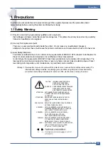
Page 3: ...ccess to laser radiation above a Class I level during normal operation user maintenance or prescribed service condition Warning Never operate or service the printer with the protective cover removed from Laser Scanner assembly The reflected beam although invisible can damage your eyes When using this product these basic safety pre cautions should always be followed to reduce risk of fire electric ...

Page 4: ...ving the power connector The power connector must be inserted com pletely otherwise a poor contact could cause overheating possibly leading to a fire When removing the power connector grip it firmly and pull 7 Take care of the power cable Do not allow it to become twisted bent sharply round corners or other wise damaged Do not place objects on top of the power cable If the power cable is damaged i...

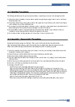
Page 5: ...he machine memory and make a note of any user settings These will be erased if the mainboard or network card is replaced 2 Ensure that power is disconnected before servicing or replacing any electrical parts 3 Disconnect printer interface cables and power cables 4 Only use approved spare parts Ensure that part number product name any voltage current or temperature rating are correct 5 When removin...

Page 6: ...et harm 3 When you move the printer This printer weighs 17 5kg including toner cartridge and cassette Use safe lifting and handling techniques Use the lifting handles located on each side of the machine Back injury could be caused if you do not lift carefully 4 Ensure the printer is installed safely The printer weighs 17 5Kg ensure the printer is installed on a level surface capable of supporting ...

Page 7: ...arges sufficient to damage ESDs 5 Do not use Freon propelled chemicals When sprayed these can generate electrical charges sufficient to dam age ESDs 6 Do not remove a replacement ESD from its protective packaging until immediately before installing it Most replacement ESDs are packaged with all leads shorted together by conductive foam aluminum foil or a compa rable conductive material 7 Immediate...

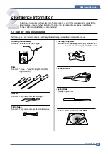
Page 8: ...e following tools are recommended safe and easy troubleshooting as described in this service manual DVM Digital Volt Meter Standard Indicates more than 3 digits Driver Standard type type M3 long M3 short M2 long M2 short Tweezers Standard For general home use small type Cotton Swab Standard For general home use for medical service Cleaning Equipments Standard An IPA Isopropyl Alcohol dry wipe tiss...

Page 9: ... Enhanced Parallel Port F W firmware GDI graphics device interface GND ground HBP Host Based Printing HDD Hard Disk Drive HV high voltage HVPS High Voltage Power Supply I F interface I O Input and Output IC integrated circuit IDE Intelligent Drive electronics or Imbedded Drive Electronics IEEE Institute of Electrical and Electronics Engineers Inc IPA Isopropy Alcohol IPM Images Per Minutes LAN loc...

Page 10: ...tern shown in below is the standard pattern used in the factory The life of the toner cartridge and the printing speed are measured using the pattern shown below The image is 70 of the actual A4 size 2 3 1 A4 ISO 19752 Standard Pattern This test page is reproduced at 70 of the normal A4 size ...

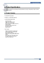
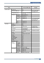
Page 11: ...usiness Customer Benefits Sales Points Fast Printing Speed 25ppm in A4 27ppm in Letter Multifunction Network Solution Scan to Email Scan to SMB Scan to FTP Duplex Capability Direct USB Connectivity 2nd Version PDF Direct Printing Small Foot Print Key Features 25 ppm Print speed 14 cpm Copy Speed 1200 dpi Print Resolution Addressable PCL6 PS3 SCX 5530FN 64MB System Memory 32MB DIMM 5530FN 50 ADF 25...

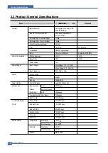
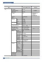
Page 12: ...110 127VAC High Voltage 220 240VAC Input Frequency 50 60Hz 3Hz Noise Printing 54dBA Copy 55dBA Standby 39dBA TBD Warm Up Time from Cold Status Less than 42 seconds Machine Life Max Monthly Print 25000pages Volume Scan 1000pages Duty Cycle ADF 1000pages Average Monthly Print Volume 1500pages Machine Life 200 000pages Periodic Replacing Pickup Roller 150 000 Pages Pad Unit ADF 20 000 Pages Transfer ...

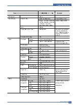
Page 13: ...n Sensing YES Font Type 45 Scalable 1 Bitmap Refer to the attached file Number N A Power Save Yes 5 10 15 30 45min Resolution Normal 600x600dpi 1200x1200 RET Yes Toner Save Yes No dedicated button on CP Memory 16MB FPOT From Stand by Approx 10 seconds From LSU ON A4 From Cold Status Less than 50 seconds Duplex Print 1815dn Yes Manual Duplex through MP tray would be possible on 1815n model Printabl...

Page 14: ...0x300dpi Photo 600x600dpi Other N A FCOT Stand by Approx 10 seconds Platen Approx 15 seconds ADF From Cold Status 50 seconds Copy Speed SDMC at all mode 27cpm Ltr 25cpm A4 Letter MDSC at Text 14cpm Text Photo 600x300dpi MDSC at Photo 8cpm Mode 600x600dpi Origin Alignment Platen REAR LEFT ADF Center Resolution Scan 600x300dpi 600 600dpi Print 600 600dpi Zoom Range 25 to 400 for Platen 25 to 100 for...

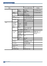
Page 15: ... Dial Yes Search Yes Phone Book by using Phone Book Button Same as Rocky 1 Touch Dial 10 Numeric Key pad No dedicated keys Speed Dial 400 locations 00 399 include Total locations can be stored 1 touch dials TAD I F Yes Tone Pulse Selectable in Technical Mode Pause Y es Auto Redial Yes Last Number Redial Yes Distinctive Ring Yes Caller ID No External Phone Interface Yes Report Tx Rx Journal Yes Lis...

Page 16: ...only for 1815dn model Multiple page scan speed 14 ppm LTR Std mode 203 x 98dpi ITU T 1 TBD Receive Mode Fax TEL Ans Fax DRPD Memory Capacity 4MB Optional Memory No Max locations to 400 locations store to 1 Group Dial Fax Forward Yes On Off Broadcasting up to 409 locations Cover page Yes Delayed fax Yes Fax Forward to Yes Enable Disable Email Addresses max 10 locations Memory RX Yes Functions Voice...

Page 17: ...r Size Max 216 x 356mm 8 5 x14 Min 76 x 127mm 3 x5 ADF Paper Weight 12 5 28lb Capacity 50 sheets Document Size Width 142mm 216mm 5 6 8 5 Document Size Length 148 mm 356mm 5 8 14 0 Document Thickness 0 075mm 0 13mm 0 003 0 005 Jam Rate Cassette 1 2000 In H H and L L condition the 2nd Feeder spec of JAM rate and Mis pickup rate Double Feed is doubled Cassette Jam 1 1000 Double Feed 1 500 ADF 1 1000 ...

Page 18: ... to network fax Accessory Quicksetupguide Yes Quick Reference Guide Yes Owner s manual Yes S W CD ROM CDs for Print Driver Scan Driver RCP S W OCR PaperPort FAX N A SCAN S W PaperPort Toner Cartridge 1 EA 3K yield ISO 19752 5 Coverage Power Cable 1 EA Telephone Jack 1 EA Printer Cable No Consumables Type One Piece Type Toner Cartridge How to install Front door open and front loading Toner Life Ini...

Page 19: ...l use 2ch available for external DMA Operation Frequency CPU Core over 300MHz System Bus 100MHz Operation Voltage Core Voltage 1 2V I O Pad Voltage 3 3V RTC Voltage 3V 2 Flash Memory Record System Program and download System Program by PC INTERF ACE FAX for Journal List and Memory for One Touch Dial Speed Dial List size 16M Byte NOR Flash Access Time 90ns Max Page Access Time 25ns Max This documen...

Page 20: ...Frequency 166MHz store Fax Receive Memory Data by using Battery 4 1 2 FAX Section Modem Part BLOCK DIAGRAM Implemented by based on Conexant DAA Data Access Arrangement Solution and is roughly composed of two kinds Chip Solution CX86710 SFX336 Existing Modem Chip which adds SSD System Side Device for interfacing between LSD and DIB of FM336Plus Core CX20493 LSD LIU Line Interface Unit Chip which is...

Page 21: ...tion ITU CRC 16 or CRC 32 check sum error detection FSK flag pattern detection during high speed receiving Tone modes and features Programmable single or dual tone generation DTMF receiver Tone detection with three programmable tone detectors Receive dynamic range 0 dBm to 43 dBm for V 17 V 29 V 27 ter and V 21 Channel 2 9dBm to 43 dBm for V 34 half duplex Digital speaker output to monitor receive...

Page 22: ...transfer Clock by separating Primary and Secondary and amplifies Clock Level to LSD by Coil Turns Ratio 1 1 16 Clock Clock is supplied by transformer from SSD to LSD and there is PWROUT to adjust output impedance of Clock Out Driver is inside SSD and CLKSHIGH Resistor to adjust duty of HLPWR Resistor and Clock Clock from SSD to LSD has Differential structure of 180 phase difference for Noise Robus...

Page 23: ... Color Black ON HOOK state Characteristic 1 DC Resistance DP Dial Mode Direct Current 30mA 50 300ohm DTMF Dial Mode Direct Current 20mA 50 540ohm 2 Ring Sensitivity Ring detection Voltage 40Vrms 150Vrms condition Current 25mA Frequency 15Hz product Margin 30Vrms 150Vrms Ring detection Frequency 15 3Hz 68Hz condition Voltage 45Vrms Current 25mA product Margin 15Hz 70Hz Ring detection Current 20mA 1...

Page 24: ...n Image Control Specification Minimum Scan Line Time 0 75ms Scan Resolution Max 600DPI Scan Width 216mm main function Internal 12bit ADC White Shading Correction Gamma Correction CCD Interface 256 Gray Scale 3 CCD Operating Part CCD Image sensor use 5V and Inverter uses 24V CCD Maximum Operating Frequency 10MHz CCD Line time 0 75ms White Data output Voltage 0 7V 0 5V Mono Copy 0 75ms line Maximum ...

Page 25: ... pre transfer lamp driving current driving and fan driving The signals from the paper feed jam sensor and paper empty sensor are directly inputted to the main board Printing Method Laser based Electro photography Supported Operating Systems Windows 98 2000 2003 NT4 0 ME XP MAC English only no status monitor web download only Linux Red Hat 8 0 9 0 Fedora Core 1 3 Mandrake 9 0 10 2 SuSE 8 2 9 2 Emul...

Page 26: ...r external DMA HPVC Dual Single Beam LVDS Pad VDO HSYNC Support A4 600dpi multi pass color PVC Dual Single Beam LVDS Pad VDO HSYNC Support A3 1200dpi multi pass color UART 5 Channels Channel0 supports DMA interrupt Operation INTERRUPT 6 External Interrupts 26 Internal Interrupts TIMER 6 System Timers CIP4e 300 400 600 1200dpi CIS CCD image sensor interface Color Mono grey image Binary image scan s...

Page 27: ...tator Scaler Halftoner support Engine Controller LSU Interface unit contained APC function Step Motor 4 Phase PWM 8 Channels ADC 8 Channels BLDC clock support APC DAC 2 ea I2C Controller I2C bus SM bus Slave Device Support I2C Version 2 1 RTC RTC Core Voltage 3V PLL 2 PLL MAIN H PVC ...

Page 28: ...Service Manual System Outline 4 10 ...

Page 29: ...dstock Transparency Copy Speed Platen SDMP 27cpm Letter SDMP Single Document ADF SDMP 27cpm Letter Multiple Printout ADF MDSP 14cpm Letter Text or Text Photo MDSP Multiple 8cpm Letter Photo Document Single Printout Reduce Enlarge Platen 25 400 1 increments ADF 25 100 1 increments Non printable Area 4 mm Top Bottom and each Side Copy Count 1 to 199 Page count displayed on LCD during copy operation ...

Page 30: ...1 2KV 15 Output Voltage Trigger 6 5 Line Regulation under 3 fluctuation input 21 6V 27 6V Output Voltage Rising Time 50ms Max Output Voltage Falling Time 100 ms Max Fluctuating transfer voltage with environmental various 650 V Duty 10 5 KV Duty 90 Environment Recognition Control Method The THV PWM ACTIVE is transfer active signal It detects the resistance by recognizing the voltage value F B while...

Page 31: ...is big because there is no Feedback control Developing Voltage DEV Input Voltage 24 V DC 15 Output Voltage 200V 600V DC 3 Output Voltage Fluctuation Method PWM Control Line Regulation under 3 fluctuation input 21 6V 27 6V Load Regulation Under 3 Output Voltage Rising Time 50 ms Max Output Voltage Falling Time 50 ms Max Output Control Signal BIAS PWM the CPU output is HV output when PWM is low Supp...

Page 32: ...y 50 60 Hz Frequency Fluctuating range 47 63 Hz Input Current Under 5 0Arms 2 5Arms But the status when lamp is of f or rated voltage is inputted outputted Rated Output Power Consumption Power NO ITEM CH1 CH2 Remark 1 CHANNEL NAME 5V 24 0V 2 CONNECTOR PIN CON 3 CON 3 5V PIN 11 13 15 24V PIN 3 5 7 9 GND PIN 12 14 16 GND PIN 4 6 8 10 3 Rated Output 5V 5 24V 10 4 75 5 25V 21 6 26 4V 4 Max Output Curr...

Page 33: ...wer The AV power controls the switch with the Triac a semiconductor switch The ON OFF control is operated when the gate of the Triac is turned on off by Phototriac insulting part In other words the AC control part is passive circuit so it turns the heater on of f with taking signal from engine control part When the HEATER ON signal is turned on at engine the LED of PC501 Photo Triac takes the volt...

Page 34: ... end of the polygon mirror and the engine detects the HSYNC sig nal to arrange the vertical line of the image on the paper After detecting the HSYNC signal the image data is sent to the LSU to arrange the its margin on the paper The one side of the polygon mirror is one line for scanning 4 1 12 Fixing Part FUSER The fuser is consisted of the Heat Lamp Heat Roller Pressure Roller Thermistor and The...

Page 35: ...re for Letter size paper at 5 coverage Product Life Time 200 000 images or 5 years whichever comes first Toner CRU Initial CRU to be 3 000 pages In Box 85 grams After market CRU will be 5 000 pages 140grams Recommended Duty Cycle 1 500 pages month A4 size ISO 19752 5 coverage AMPV Printing 2 500 pages Flat bed 150 pages ADF 150 pages Max Monthly Volume Printing 25 000 pages Flat bed 1 000 pages AD...

Page 36: ...cable routing that will be affected Whenever servicing the machine you must perform as follows 1 Check to verify that documents are not stored in memory 2 Be sure to remove the toner cartridge before you disassemble parts 3 Unplug the power cord 4 Use a flat and clean surface 5 Replace only with authorized components 6 Do not force plastic material components 7 Make sure all components are in thei...

Page 37: ...e out the Cassette 2 Open the Cover 3 If necessary remove the Toner Cartridge 4 To remove the Front Cover first pull the part below the both side of the Front Cover with a light pressure to the direction of arrow Cassette Toner Cartridge Front Cover 2 1 ...

Page 38: ...y Ass y 2 Pull the Tray Links from the both side of the Front Cover with a light pressure to the direction of arrow 3 Apply light pressure to the both side of the MP Tray Ass y and pull it in the direction of arrow as shown below MP Tray Ass y MP Tray Ass y Tray Link ...

Page 39: ...e direction of arrow as shown below 2 Take out the Duplex Unit 3 Remove the four screws securing the Rear Cover and then Release the Rear Cover from the Set 4 To remove the Face Up Cover first release the Stopper Strap in the direction of arrow 2 1 DIMM Cover Rear Cover Stopper Strap 1 2 Duplex Unit ...

Page 40: ...Precautions Service Manual 5 5 5 Unlatch the Face Up Cover from the Rear Cover and then release the Face Up Cover as shown below Face Up Cover ...

Page 41: ...tat and then remove the three screws securing the Thermostat and remove it 4 To remove the Halogen Lamp first release REC Harness from the left side of the Halogen Lamp and then release the CON Harness from the right side of the Halogen Lamp as shown below 5 Remove the two screws securing the both side of the Halogen Lamp and then release in the direction of arrow as shown below Fuser Ass y CON Ha...

Page 42: ...r from the Input Guide and remove the one screw securing the Thermistor and remove it 8 Remove the three screws securing the Idle Gear Bracket and remove it 9 Remove the one screw securing the Fuser Cover and release the Fuser Cover from the Fuser Frame Input Guide Idle Gear Bracket Fuser Cover Fuser Frame Thermister ...

Page 43: ...ar and HR Bush and then remove the Heat Roller as shown below 11 Remove the Jam Link Lever L R and Jam Holder L R and then remove the Pressure Roller as shown below Heat Roller HR Bush HR Bush Fuser Gear Jam Holder Jam Link Lever Jam Holder Jam Link Lever ...

Page 44: ...3 Apply light pressure to the bottom of the Right Side Cover and pull it to the right side in the direction of arrows as shown below 4 Remove the two screws securing the Left Side Cover as shown below 5 Apply light pressure to the bottom of the Left Side Cover and pull it to the left side in the direction of arrows as shown below 5 6 Side Cover Left Right Left Side Cover Right Side Cover ...

Page 45: ...cautions 5 10 6 To remove the DIMM Cover first open the DIMM Cover refer to 5 4 1 and then release the DIMM Cover as shown below Notice Be careful not to damage the hooks when remove the Side Cover Left Right DIMM Cover ...

Page 46: ...fer to 5 6 2 Remove the two screws securing the Scanner Ass y as shown below 3 Remove the one screw securing the Ground Cable and unplug the four connectors and CCD Cable 4 Pull up the Scanner Ass y as shown below 5 Release the ADF Harness from the underneath the Scanner Ass y 5 7 Scanner Ass y Scanner Ass y ADF Harness ADF Ground Cable ...

Page 47: ... the direction of arrow 8 Unplug the three connectors from the OPE PBA as shown below and then release the Battery 9 Remove the four screws securing the Scan Upper 10 Release the four hooks securing the Scan Upper to the Scan Lower and remove it as shown below 11 Remove the CCD Cable as shown below ADF Ass y Scanner Battery OPE Unit Scan Upper Scan Lower CCD Cable OPE Unit ...

Page 48: ...15 If necessary remove the two screws securing the Scan Motor and remove it as shown below Caution Reassembling CCDM 1 When refitting the Scanner Belt and Belt Spring take care to relocate the tension spring as close to the right side of the CCDM as is possible as shown below 2 When refitting the Scan Upper Cover take care to ensure that the Cover Open Switch is not trapped CCDM CCD Shaft Scan Mot...

Page 49: ...om the Open Sensor Ass y 17 Unlatch the Open Sensor and remove it as shown below 18 Remove the CCD Holder 19 Unplug the Harness from the CCD Home Sensor and release the CCD Home Sensor as shown below CCD Home Sensor Harness Sensor Lever Open Sensor CCD Holder ...

Page 50: ...screws securing the ADF Engine Ass y and remove it Notice Take care to thread the ADF Harness through the Platen Cover Ass y 4 Remove the Open Cover as shown below Notice When working on the ADF Motor Ass y take care not to contaminate any of the rubber surfaces with grease 5 Release the Bush and rotate it until it reaches the slot as shown below Then lift the Pick Up Ass y out ADF Harness Platen ...

Page 51: ...te Core and the Motor Harness routing When refitting the ADF Engine Ass y ensure that the Harness and Ferrite are properly located and are clear of the Motor Fan and White Bar Clip 7 Unplug the one connector and remove four screws securing the ADF Motor Ass y and then remove the one screw securing the Ground Cable as shown below Then take out the ADF Motor Ass y ADF Motor Ass y ADF Lower ADF Upper...

Page 52: ...fer to 5 4 Side Cover Left Right Refer to 5 6 Scanner Ass y Refer to 5 7 2 Remove the five screws securing the OPE PBA from to the OPE Cover 3 Remove the Contact Rubber from the OPE Cover 4 Remove the Keys from the OPE Cover 5 9 OPE Unit OPE PBA OPE Cover Select Key Menu Key Tel Key Contact Rubber ...

Page 53: ... securing the Shield Controller Ass y and remove it 4 Remove the three screws securing the Main PBA to the Bracket and unplug the Film Cable and then remove the Main PBA 5 The connectors are located as shown below 5 10 Shield Controller Ass y Shield Film Cable Main PBA ADF Flat Motor Flat Cover CCD OPE Panel USB Host Cartridge USB Line Modem PBA Duplex Motor Engine BLDG Pick Up REGI LSU_5V LSU The...

Page 54: ...ring the Modem PBA to the Bracket and unplug the Film Cable and then remove the Modem PBA 7 Remove the two screws securing the Speaker to the Bracket and unplug the connector from the Modem PBA and then remove the Speaker Modem PBA Shield Film Cable Shield Speaker ...

Page 55: ... remove it Notice The six screws have numbers stamped into the Drive Ass y base plate When refitting the Drive Ass y tighten the screws the order they are numbered Only screws numbered 1 to 5 are fitted at this stage Screw 6 is fitted when the Shield Controller Ass y is refitted 3 If necessary remove the four screws securing the BVDC Motor Ass y and remove it 5 11 Drive Ass y Drive Ass y Gear Brac...

Page 56: ...er Right Refer to 5 6 3 2 Unplug the connector from the Connection PCB and remove the three screws securing the Duplex Drive Unit and remove it 3 If necessary remove the two screws securing the Duplex Motor and remove it 5 12 Duplex Drive Ass y Duplex Drive Ass y Connection PCB Duplex Motor Harness Duplex Motor Bracket Ass y ...

Page 57: ...efer to 5 6 3 Duplex Drive Ass y Refer to 5 12 2 Unplug the two connectors HVPS Fuser 3 Remove the three screws securing the Shield SMPS Ass y and remove it 4 Unplug the connector AC Inlet and remove the four screws securing SMPS and remove it HVPS Connector Fuser Connector Shield SMPS Ass y SMPS Insulator Sheet Shield SMPS With AC Inlet AC Inlet Connector ...

Page 58: ... you should remove Rear Cover Refer to 5 4 Side Cover Right Refer to 5 6 3 2 Unplug the all connectors 3 Remove the two screws securing the Connection PCB and remove it 4 The connectors are located as shown below Connection PCB Connection PCB FAN Duplex Exit Motor Fan Main HVPS Duplex Motor ...

Page 59: ... Refer to 5 4 Side Cover Right Refer to 5 6 3 2 Unplug the connector from the Connection PCB 3 Remove the three screws securing the Fuser Drive Ass y and remove it 4 If necnsary remove the two screws securing the Step Motor and remove it Fuser Drive Connection PCB Fuser Drive Ass y Step Motor Harness Fuser Exit Bracket Ass y ...

Page 60: ... remove Rear Cover Refer to 5 4 Side Cover Right Refer to 5 6 3 2 Unplug the two connectors from the Connection PCB as shown below 3 Remove the two screws securing the Fans and then pull the Fans Main Duplex Main Fan Duplex Fan Connection PCB Duplex Fan Main Fan 5 16 Fan ...

Page 61: ...to right and it will be released completely as shown below 3 To remove the Shaft first release the locker and slide the Shaft from left to right then lift the notch attached to the Cam so that it s released from the Shaft Then release the Bush from the Shaft and remove the Shaft from the Duplex Guide Housing as shown below 5 17 Pick Up Roller Ass y Cassette Pick Up Roller Ass y 1 2 2 1 Cam Bush Sh...

Page 62: ...e Pick Up Roller Ass y Refer to 5 17 2 Remove the two screws securing the Duplex Guide Housing 3 Unplug the one connector Photo Interrupter and remove the Duplex Guide Housing with Feed Roller as shown below 4 Pull the Feed Roller from the Bushing Bushing Feed Roller Duplex Guide Housing Photo Interrupter Connector Duplex Guide Housing ...

Page 63: ...to 5 18 Unplug the two Connectors HVPS p5 22 2 Remove the eight screws securing the HVPS Housing as shown below 3 Unplug the connector for connection PBA SMPS first Unplug the other connectors 4 If necessary remove the three screws securing the HVPS and remove it HVPS Housing HVPS Insulator Sheet Shield 5 19 HVPS Housing Duplex Motor Connection PBA SMPS Engine Duplex Guide Housing ...

Page 64: ...gile take care when removing it Cover Mid Front Hook Hook 5 20 Middle Cover Ass y 1 Before you remove the Middle Cover Ass y you should remove Rear Cover Refer to 5 4 Side Cover Left Right Refer to 5 6 Scanner Ass y Refer to 5 7 Shield Controller Ass y Refer to 5 10 2 Remove the six screws securing the Middle Cover Ass y and remove it 3 If necessary remove the two screws securing the USB Host PBA ...

Page 65: ... screws securing the MPF Housing and remove it 3 To remove the MP Pick Up Ass y first lift the notch attached to the left side Stopper so that it s slide the right to left from the Shaft then left side Idle slid the right to left from the Shaft and take out the MP Pick Up Ass y as shown below MPF Housing Stopper 1 2 Idle MP Pick Up Ass y MPF Housing ...

Page 66: ...using Refer to 5 22 2 Remove the two screws securing the both side of the Guide Paper and then remove the Guides 3 Pull up the Feed Idle Shaft and the Bushs with Spring 4 Release the E Ring securing the Feed2 Gear and remove it 5 Remove the three screws securing the Feed Bracket Unit and then remove the Feed Bracket Unit and Feed2 Shaft Guide Paper Feed Idle Shaft Bush Srring Feed2 Gear E Ring Fee...

Page 67: ...hen remove the Gears from the Feed Bracket as shown below Notice Be aware of the E Rings to ensure they are not lost 7 Remove the Clutch Unit as shown below 8 Pull up the Feed1 Roller from the Bushing as shown below T2 Idle Gear Retard Gear Idle Gear E Ring Bracket Feed Shaft Feed1 Gear Ass y Clutch Unit Feed1 Roller ...

Page 68: ...ear Roller Exit F Down Exit Roller Rack Bearing 5 25 Exit Roller 5 24 Pick Up Gear Ass y Solenoids 1 Before you remove the Pick Up Gear Ass y Solenoids you should remove Duplex Guide Housing Refer to 5 18 Feed Bracket Unit Refer to 5 23 5 2 Release the Pick Up Gear Ass y and Pick Up Gear Shaft as shown below 3 Remove the two screws securing the Manual Solenoid and Feed Solenoid and then remove the...

Page 69: ...he LSU and remove it 5 26 LSU LSU 1 Before you remove the CRUM2 PBA you should remove Middle Cover Ass y Refer to 5 20 LSU Refer to 5 26 2 Remove the one screw securing the CRUM2 PBA and remove it and then release the four Terminals as shown below Notice Be aware of the Terminals to ensure they are not lost Terminal PBA Terminal 5 27 Terminal PBA ...

Page 70: ...older and then take out the Transfer Roller as shown below Notice Do not grab the rubber part of the Transfer Roller it may cause a malfunction due to a foreigen object Hole the both side of the Transfer Roller when replacing it TR Holder 2 1 Transfer Roller 5 28 Transfer Roller Parts ...

Page 71: ...thod the test output related to maintenance and repair DCU using method Jam removing method and so on It includes the contents of manual 6 1 Paper path Scanner Part Engine Part Roller Heat Roller Exit Roller Exit Roller Transfer Roller Pickup Roller Feed Roller Feed Roller MP Roller Pressure Roller REGI OPC Duplex Duplex Roller REGI OPC Roller ADF Roller Pickup ...

Page 72: ...The front cover has been opened during a print job Paper was used that does not meet paper specifications Paper that is outside of the supported size range was used If a paper jam occurs LCD window will show it s speeds Find and remove the jammed paper If you don t see the paper open the covers Do not use a pinset or a sharp metal tool when removing a jam The covering of a metal part can be remove...

Page 73: ...am appears on the display NOTE To prevent document jams use the document glass for thick thin or mixed documents 1 Remove the remaining documents from the ADF If the document is jammed in the paper feed area a Open the ADF cover b Remove the document by gently pulling it out c Close the ADF cover Then reload the document into the ADF ...

Page 74: ...he documents back into the ADF 2 If you cannot see the paper or the paper does not move when you pulled open the document cover 3 Turn the release knob so that you can easily seize the misfed document and remove the document from the roller or the feed area by carefully pulling it gently to the right 4 Close the document cover Then load the documents back into the ADF Service Manual Alignment Adju...

Page 75: ...e paper by gently pulling it straight out If you cannot see the paper or the paper does not move when pulled check the fuser area For more information see Fuser Area Jam 4 Insert the paper tray into the printer until it snaps into place Printing automatically resumes Paper Jam 0 Paper Feed Jam tray 1 Paper Feed Jam tray 1 or Open Front Door Paper Feed Jam optional tray 2 Paper Feed Jam optional tr...

Page 76: ... paper from the printer If you cannot see the paper in this area or the paper does not move when pulled go to the next step 3 Pull the tray 1 half 4 Pull the paper straight up and out 6 2 5 Bypass tray Jam 1 If the paper is not feeding properly pull the paper out of the printer 2 Open and close the front cover to resume printing ...

Page 77: ...nd close the front cover Printing automatically resumes 6 2 7 Paper Exit Jam 1 Open and close the front cover The jammed paper automatically exits the printer If the paper does not exit go to the next step 2 Gently pull the paper out of the output tray 3 If you cannot see the paper in the output tray or the paper does not move when pulled open the rear cover 4 If you see the jammed paper push the ...

Page 78: ...fuser door NOTE Make sure to unfold the fuser guide before opening the fuser door or you may damage the fuser door 8 Pull the jammed paper out If the jammed paper does not move when you pull push the two blue pressure levers up to loosen the paper and then remove it 9 Return the levers fuser door rear cover stopper and duplex guide to their original position 10 Close the rear cover Printing automa...

Page 79: ...t out of the printer 2 Remove the jammed paper from the duplex unit If the paper does not come out with the duplex unit remove the paper from the bottom of the printer 3 Push the duplex unit to the printer CAUTION If you do not push the duplex unit in correctly a paper jam may occur ...

Page 80: ...ual Alignment Adjustments 6 10 6 2 9 Duplex Jam 1 1 Open the rear cover 2 Unfold the duplex guide fully 3 Pull the jammed paper out 4 Return the duplex guide and close the rear cover Printing automatically resumes ...

Page 81: ...ial No Stamp RCV Name ECM Mode 6 Reports Phone Book Send Report RCV Report System Data Scheduled Jobs Tx Confirm Junk Fax List 7 Sound Volume Speaker Ringer Key Sound Alarm sound 8 Machine Setup Machine ID Date Time Clock Mode Dial Mode Language Power Save CCD Power Save USB Mode 9 Maintenance Clean Drum Notify toner Clear Memory 6 3 User Mode Dell Laser MFP1815dn The table in the bellow explains ...

Page 82: ...k the machine and perform various test to isolate the cause of a malfunction While in Tech mode the machine still performs all normal operations To enter the Tech mode To enter the Tech mode press in sequence and the LCD briefly displays TECH the machine has entered service tech mode 6 4 2 Setting up System in Tech Mode MFP1815dn ...

Page 83: ...alue You can select the rate between 5 and 10 CLEAR ALL MEMORY The function resets the system to factory default settings This function is used to reset the system to the initial value when the product is functioning abnor mally All the values are returned to the default values and all the information which was set by the user will be erased Method 1 Select the MEMORY CLEAR at the TECH MODE 2 Push...

Page 84: ...grade Save the files in the same folder 2 In the DOS input as below and push the enter key Then it will be automatically upgraded 3 There are two commands for the conditions of product When the product is in idle condition down rom file When the product is in Ready condition TECH MODE DATA SETUP FLASH UPGRADE LOCAL fprt rom file 4 Do not turn off the power while upgrading process 2 Remote FAX This...

Page 85: ...o test the machine S ROM The result and the software version appear in the LCD display FLASH VER 1 00 V ENGINE VER 1 00V PATTERN TEST Using this pattern printout you can check if the printer mechanism is functioning properly It is needed in the production progress Service person doesn t need to use it SHADING TEST The function is to get the optimum scan quality by the specific character of the CCD...

Page 86: ...T 30 protocol during the most recent sending or receiving operation Use this list to check for send and receive errors If a communication error occurs while the machine is in TECH mode the protocol list will print automatically SYSTEM DATA This list provides a list of the user system data settings and tech mode settings ...

Page 87: ...f 1550V 50V 2 Dev Bias Test 1 On 2 Off 430V 20V 3 THV EN NEG Test 1 On 2 Off 1000V 300V 150V 4 THV ON 1300V 1 On 2 Off 1300V 20V 5 THV ADC 1300V 1 On 2 Off ADC Value 101 5 6 THV ADC 600V 3500V 1 On 2 Off Compare each ADC Value 6 5 Engine Test Mode The Engine Tests Mode supplies useful functions to check the condition of the engine It tests the condition of each device and displays the result of th...

Page 88: ...ady is displayed When the Laser Scanning Laser Leady On Off Unit is ready to print On the other case Laser Error 13 LD Test Diode On is displayed when the laser diode is on Diode On Off On the other case Diode Off is displayed 21 Feed Sen Test These Functions are considered to check the present Sensor Off to Sensor On 22 Exit Sen Test state normal or not of the Sensors 23 Cover Sen Test After the ...

Page 89: ...t operate the machine it will start a scan and page count The time the machine was first used is remembered These settings are are remembered after memory delete Clear All Memory Method Press MENU 1 9 3 in sequence Firmware version is displayed on LCD Press 1 in the number keypad The LCD display shows Updated date Press 2 in the number keypad The LCD display shows Product first use date ...

Page 90: ...e of 50 transmitted and received documents per day Environmental conditions and actual use will may vary The cycle period given below is for reference only COMPONENT REPLACEMENT CYCLE ADF Rubber 20 000 Pages ADF Roller 60 000 Pages Pick up Roller 150 000 Pages Friction Pad Paper Tray 150 000 Pages Transfer Roller 70 000 Pages Fuser 80 000 Pages Toner Cartridge 4 000 Pages A4 ISO 5 Pattern ...

Page 91: ...e spot Block spot 2 Charge Roller 37 7mm Black spot 3 Supply Roller 44 9mm Horizontal density band 4 Develop Roller 35 2mm Horizontal density band 5 Transfer Roller 47 1mm Black side contamination transfer fault 6 Heat Roller 77 8mm Black spot and fuser ghost 7 Pressure Roller 75 4mm Black side contamination 1 2 3 4 OPC Drum Charge Roller Supply Roller Developing Roller 5 6 7 Transfer Roller Heat ...

Page 92: ...r and close the fuser door until it locks into place For the location of the fuser door see Paper Exit Jam Group Not Available You have tried to select a group location Use a speed dial number or dial the number where only a single location number manually using the number number can be used such as when keypad adding locations for a broadcasting operation Hsync Error A problem has occurred in the...

Page 93: ...s jammed in the feeding area Clear the jam See Paper Feed Jam Open Front Door of the paper tray tray 1 or Paper Feed Jam optional tray 2 Paper Jam 1 Paper has jammed in the fuser area Clear the jam See Fuser Area Jam Cartridge Area Pager Jam 2 Paper has jammed in the paper exit area Clear the jam See Paper Exit Jam Open Rear Door Power Failure The power has been turned off and then The printer s m...

Page 94: ...artridge EXIT Sensor Feed Sensor MP Sensor Check and Cause Solution 1 Check the Pickup Solenoid by using Engine Test Mode Diagnostic Mode 2 Check if the friction pad is loose in the paper tray 3 Check the surface of the roller pickup for foreign matter 4 If continuous clusters occur check whether the assembly slot between shaft pickup and housing pickup become open or is broken away 5 If the paper...

Page 95: ...t sensor actuator is defective Check if the actuator exit is deformed Check if the lever part is deformed in shape Check whether burrs occur in the assembly part of the actuator exit or not and if the actuator is smoothly operated Check if foreign matters and wire get caught in the actuator exit s operation 2 If the paper is stuck in the fuser dis assemble the fuser and remove the jammed paper and...

Page 96: ...oid if necessary 2 Clean the friction pad with soft cloth dampened with IPA Isopropyl Alcohol 3 Use the smooth paper 7 1 6 Paper rolled in the fuser Description If contaminated at intervals of 57mm on the back of a paper Check and Cause Solution 1 Contamination of the pressure roller Background Hot off set 1 Disassemble the fuser clean the area between the Heat roller and Thermistor and remove the...

Page 97: ... OPC against the ongoing direction Clean fingerprints on the OPC softly with soft cloth dampened with IPA Isopropyl Alcohol or tis sue 7 1 8 Defective ADF Description ADF Automatic document Feeder is not properly operated Check and Cause Solution 1 Check if ADF rubber and HOLDER rubber are dam aged 2 Check if the document sensors of ADF Ass y 3 paper sensors are normal 1 Replace the contaminated o...

Page 98: ...y again after clearing the memory 2 After confirming that OPE HARNESS is connected to the Main B d correctly if it is so then replace the OPE Ass y and Main Board in sequence 7 2 2 Defective LCD Operation Description Defective LCD Operation Check and Cause Solution 1 Clear the memory 2 Confirm to catch a click sound while a key on the OPE panel is pressed on 1 The key is wrong itself or wrongly as...

Page 99: ... Bending or deformation of the actuator of the paper sen sor 2 The function of the Main PBA is defective Perform Engine Test Mode Perform Engine Test Mode 1 Replace the defective actuator 2 Replace the Main PBA 7 2 5 Paper Empty without indication Description Paper empty sign does not come on when the paper cassette is empty Check and Cause Solution 1 Bending or deformation of the actuator of the ...

Page 100: ...tment in the Main PBA 1 Replace the hook lever if defective 2 Check the insertion of the Door Open S W Connect 3 Replace the Main PBA or Door Open S W 7 2 7 No Beep on when the Door is open Description The ERROR lamp does not come on even when the printer Door is open Check and Cause Solution Check the Connector CN1 and Circuit of the Cover Switch department in the Main PBA 1 Check the insertion o...

Page 101: ...heck the Motor operation 1 Check the Motor harness replace it if defective 2 Replace the SMPS if necessary 7 2 9 No Power Description When system power is turned on all lamps on the operator panel do not come on Check and Cause Solution 1 Check if the power input and SMPS output are normal 2 Check for defective of LCD Panel on the front cover if the LCD of Panel does not appear after normal warmin...

Page 102: ...ved Description When printing vertical line gets curved Check and Cause Solution 1 If the supply of 24v is unstable in the Main Control board linking with LSU check drive by Engine Test Mode Diagnostic Code 1 LSU Motor on 1 Replace LSU 2 Replace the Main Control board ...

Page 103: ...nter Check and Cause Solution 1 Foreign matter stuck onto the window of internal lenses of LSU mirror 2 Foreign matter or toner particles between the developer roller and blade In case the life of the developer has been expired white lines or light image occur in front of the image 3 It may occur when a Burr and foreign substances are on the window of the developer frame 4 If the fuser is defectiv...

Page 104: ...ital Printer Digital Printer Digital Printer Digital Printer Check and Cause Solution 1 If dark or blurry black spots occur periodically the rollers in the Developer may be contaminated with foreign matter or paper particles Charge roller 37 7 mm interval OPC drum 75 5 mm interval 2 If faded areas or voids occur in a black image at intervals of 75 5 mm or black spots occur elsewhere the OPC drum s...

Page 105: ...rint out 3 No 2 Wait 30 minutes after printer is pow ered on before you start printing 4 No3 Clean up the contaminated area by the toner 5 Replace the HVPS if the problems are not solved by the above four directions 7 3 6 Dark Image or a Black Description The printed image is dark Digital Printer Digital Printer Digital Printer Digital Printer Digital Printer Check and Cause Solution 1 No charge v...

Page 106: ...lace both the left and right Spring Holder 2 Problem with the toner cartridge replace the toner cartridge and try to print out 7 3 8 Background Description Light dark background appears in whole area of the printing Digital Printer Digital Printer Digital Printer Digital Printer Digital Printer Check and Cause Solution 1 Recycled recording paper has been used 2 The life of the Developer has expire...

Page 107: ...inated terminals 2 Problem in the toner cartridge replace the toner cartridge and try to print out 3 Replace the engine board if not solved by the above directions 1 2 4 If not solved by the direction 3 check the transfer roller lifetime and replace it 5 Wait about 1 hour after power on before using printer 6 Problem in the toner cartridge replace the toner cartridge and try to print out 7 3 10 Gh...

Page 108: ...italPrinter DigitalPrinter DigitalPrinter DigitalPrinter DigitalPrinter 77 8 mm Check and Cause Solution The temperature of the fuser is maintained high 1 Disassemble the fuser and remove the contaminated toner particles on the roller and clean the foreign matter between Thermistor and Heat roller Caution can be deformed 7 3 13 Stains on the front of the page Description The background on the face...

Page 109: ...15 Blank Page Print out 1 Description Blank page is printed Digital Printer Digital Printer Digital Printer Digital Printer Digital Printer Check and Cause Solution Bad ground contacts in OPC and or devel oper Remove contamination of the terminals of the toner cartridge and the printer 7 3 16 Blank Page Print out 2 Description 1 Blank page is printed 2 One or several blank pages are printed 3 When...

Page 110: ... defective Try to replace the OPE Ass y 3 Check the Speaker connection and try to replace it 4 Lastly try to replace the Main B d 7 4 2 Defective MF DIAL Description The MF DIAL is not functioning Check and Cause Solution 1 Check if the telephone line is connected correctly 2 Wile the BUTTON KEY is pressed check to catch a CLICK sound 3 Check the connection of HARNESS between the LIU and the Main ...

Page 111: ... LIU B d 2 If the MODEM testing is abnormal try to replace the Main B d 7 4 4 Defective FAX FORWARD Description RECEIVE is functioning but FORWARD is not functioning or the received data are broken Check and Cause Solution 1 Check if there is NOISE when pressing on hook dial 2 Check the RECEIVE condition by trying to forward a FAX to another fax machine from the forwarding side FAX 3 Check if the ...

Page 112: ...ing on hook dial 2 Ask to the forwarding side check the image quality of another machine receiving a FAX additionally sent to 1 If it makes NOISE rearrange the telephone line Refer to Defective FAX RECEIVE 2 Check if the FAX status of the forwarding side is also normal Check and Cause Solution Check if the RECEIVE Mode is TEL MODE or FAX MODE Even when the RECEIVE Mode is changed to FAX MODE it ca...

Page 113: ... Check and Cause Solution Check the FAX status of the forwarding side After checking the data of the forwarding side correct the FAX of the forwarding side Check and Cause Solution 1 Check if the RECEIVE Mode is TEL MODE or FAX MODE 1 If the RECEIVE Mode is set to the TEL MODE reset it to the FAX MODE 2 Even after the RECEIVE Mode is changed to the F AX Mode it cannot receive then try to replace t...

Page 114: ...white black reference voltage in Main PBA 1 Room light ca transit a thin original 2 Remake shading profile in the tech mode 3 Replace U60 if it is defective U60 154 0 5V U60 155 3 3V 7 5 2 Black Copy Description Black page is printed out when Copy Check and Cause Solution 1 Check the CCD problem in Main PBA 2 Check shading profile 1 Check the CCD harness contact 2 Remake shading profile in the tec...

Page 115: ...ght or bad Check and Cause Solution 1 Check shading profile 2 Check the gap between original and scanner glass 3 Check printing quality 1 Remake shading profile in the tech mode 2 The gap above 0 5 mm can cause a blurred image 3 See Print troubleshooting 1 Check the right position of the Scanner Motor and check the any mechanical disturbance in the CCD carriage part 2 If any driver is defective re...

Page 116: ...t related to driver setup if it is not so rein stall it Refer to User s Manual 3 If copy function works replace the Main PBA If copy function doesn t work replace the CCD Ass y and try again 7 6 2 Defective Image Quality of PC Scan Description The image PC scanned is not clear or bad Check and Cause Solution 1 Check the waveform form by performing a CCD test in TECH Mode 2 Check if the resolution ...

Page 117: ...LCD displays the warning mes sage Toner Low You can temporarily reestablish the print quality by redistributing the remaining toner in the cartridge 7 7 3 Service for Judgement of Inferior Expendables and the Standard of Guarantee Please refer to User s Manual or Instructions on Fax Printer Expendables SVC for the judgement of inferior expend ables and the standard of guarantee besides this servic...

Page 118: ...er periodically 1 Check the cycle of the falling of the toner 2 Check the appearance of both ends of the developer OPC drum 2 The center of the printed mat ter is contaminated with toner 1 Check whether foreign sub stances or toner are stuck to the terminal contact point of the developer 2 Check whether the state of the terminal assembly is normal 1 All of 1 2 3 above 1 The weight of the developer...

Page 119: ...printouts 1 Check whether foreign sub stance or toner are stuck to the terminal contact point of the developer 2 Check whether the state of the terminal assembly is normal 1 In case of 1 above Run OPC Cleaning Mode Print 4 5 times repeatedly to remove Especially check foreign sub stance on the OPC surface then remove them with a clean gauze moistened with IP A Isopropyl Alcohol not to damage OPC i...

Page 120: ...charged roller terminal 3 The printed image is dark and ghost occurs 1 Check foreign substance attached to the terminal point of contact of the developer and the state of assembly Especially check the devel oping roller terminal 1 All of 1 2 3 above 1 Remove toner and foreign sub stances adhered to the contact point of the developer 2 The contact point of the unit facing that of the developer also...

Page 121: ...ng succeeds verify that community names with sufficient permissions have been used Check the environment as described in Auto Detection of Print Server Check NetWare file server consoles for error messages regarding nodes with conflicting network numbers On Network Interface in SyncThru you should set Static to IP Address Assignment Method in TCP IP tab You should set IP address Subnet Mask and De...

Page 122: ...Thru The print server name is displayed but the test page is not printed Firmware upgrade process is completed But upgrading is not executed 1 Verify that the printer power switch is turned on and the READY message is displayed on the printer front panel 2 Verify that the LAN cable is plugged into the PortThru card 3 Verify that the second LED on the PortThru card blinks If the second LED blinks r...

Page 123: ...N If LAN is connected by routers SyncThru is unable to detect the printers In this case one of protocols which are enabled in NPC should be Installed in the computers 4 In case that the protocol which is enabled in NPC is installed in the computers If TCP IP installed check entry values of IP address subnet mask and default gateway Try Add a Port 7 8 4 SyncThru Installation Problems Problem Soluti...

Page 124: ...4 8 4 Front Cover Ass y page 8 5 8 5 Rear Cover Ass y page 8 6 8 6 Frame Assembly page 8 7 8 7 Fuser Drive Ass y page 8 8 8 8 Main Drive Ass y page 8 9 8 9 MP Ass y page 8 10 8 10 ADF Ass y page 8 11 8 17 Cover Platen Ass y page 8 12 8 16 OPE Unit page 8 13 8 15 Scanner Ass y page 8 14 8 14 Cassette Ass y page 8 15 8 15 Fuser Ass y page 8 16 8 16 Duplex Unit page 8 17 ...

Page 125: ...Service Manual Exploded View Parts List 8 2 8 1 Main Exploded Views 33 0 12 11 10 14 13 9 8 8 1 23 23 1 7 6 16 17 3 1 2 24 25 15 26 27 5 4 4 1 4 2 4 3 28 29 30 31 32 32 32 ...

Page 126: ...Exploded View Parts List Service Manual 8 3 8 2 Cover Ass y 0 1 2 2 3 2 1 2 2 3 4 5 5 1 5 2 6 ...

Page 127: ...Service Manual Exploded View Parts List 8 4 8 3 Middle Cover Ass y 0 1 2 3 4 5 6 6 ...

Page 128: ...Exploded View Parts List Service Manual 8 5 8 4 Front Cover Ass y 0 1 2 3 4 5 10 10 8 9 7 6 11 ...

Page 129: ...Service Manual Exploded View Parts List 8 6 8 5 Rear Cover Ass y 0 1 2 3 7 4 5 6 8 ...

Page 130: ...1 8 2 8 3 8 4 8 5 13 10 1 10 2 10 3 3 1 3 2 3 3 3 4 3 5 3 6 14 4 1 4 1 4 2 4 3 4 4 4 5 4 6 4 7 14 15 16 17 17 18 19 20 21 22 23 24 25 26 27 27 28 29 30 31 68 32 33 34 32 35 36 36 1 36 2 36 3 36 4 37 38 39 40 41 42 43 44 45 46 47 48 52 52 1 53 54 55 56 57 58 59 60 Transfer Roller 0 62 62 49 50 51 61 67 66 65 64 63 ...

Page 131: ...Service Manual Exploded View Parts List 8 8 8 7 Fuser Drive Ass y 0 1 2 3 5 5 6 7 8 9 4 ...

Page 132: ...Exploded View Parts List Service Manual 8 9 8 8 Main Drive Ass y 0 2 4 1 3 5 6 8 7 6 7 3 ...

Page 133: ...Service Manual Exploded View Parts List 8 10 8 9 MP Ass y 0 1 2 2 1 2 2 2 3 2 4 2 5 2 6 3 4 5 6 7 8 9 10 11 12 13 14 15 16 17 17 1 17 2 17 3 18 19 20 21 22 23 24 25 26 24 27 ...

Page 134: ... 1 12 1 13 1 14 1 15 1 16 1 17 1 18 1 19 1 20 1 21 2 1 2 2 2 19 2 3 2 4 2 5 2 6 2 7 2 8 2 10 2 9 2 8 2 8 2 11 2 12 2 13 2 14 2 11 2 15 2 20 2 16 2 17 2 18 3 3 2 4 3 1 3 2 3 2 2 3 2 1 3 2 3 3 2 5 4 5 5 1 5 2 5 2 5 3 6 4 1 4 2 4 3 4 17 4 18 4 19 4 4 4 12 4 10 4 11 4 9 4 15 4 5 4 6 4 8 4 8B 4 8A 4 7 4 13 4 14 4 15 4 16A 4 16B ...

Page 135: ...Service Manual Exploded View Parts List 8 12 8 11 Cover Platen Ass y 0 1 1 1 1 2 1 3 1 4 1 5 2 3 4 4 5 6 7 7 5 8 9 ...

Page 136: ...Exploded View Parts List Service Manual 8 13 8 12 OPE Unit 0 1 2 3 4 5 6 7 8 ...

Page 137: ... Parts List 8 14 8 13 Scanner Ass y 0 1 1 1 1 1 2 1 1 3 1 1 1 1 1 6 1 1 7 1 1 8 1 2 1 5 1 5 1 4 1 3 2 2 2 6 2 2 2 2 5 2 2 4 2 2 3 2 2 2 2 2 1 2 2 7 2 3 2 4 2 5 2 10 2 12 2 11 2 13 2 14 2 9 2 8 2 7 2 6 2 1 2 19 2 13 2 15 2 17 2 18 ...

Page 138: ...Exploded View Parts List Service Manual 8 15 8 14 Cassette Ass y 0 1 2 3 4 4 2 4 1 4 3 4 4 5 6 7 7 8 9 10 11 12 13 14 15 ...

Page 139: ...Service Manual Exploded View Parts List 8 16 8 15 Fuser Ass y 1 2 1 2 2 2 3 2 4 3 9 4 5 6 7 8 10 11 12 13 15 16 17 18 19 20 21 22 23 24 25 26 27 27 28 29 30 31 32 33 34 35 36 37 39 0 ...

Page 140: ...Exploded View Parts List Service Manual 8 17 8 16 Duplex Unit Optional 0 1 2 9 3 4 5 6 16 7 3 8 8 5 10 8 10 11 12 13 14 15 9 ...

Page 141: ... 8 1 27 JC63 00913A SHIELD P SMPS 1 X 8 1 28 JC39 00523A CBF HARNESS AC INLET 1 X 8 1 29 JC61 01653B STOPPER M_STRAP 1 X 8 1 30 JC63 00960A SHEET INSULATOR_SMPS 1 X 8 1 31 JC44 00097A SMPS PSP_TYPE3_V1 1 O 8 1 31 JC44 00090A SMPS PSP_TYPE3_V2C 1 O 8 1 32 JC72 00382B PMO BUSHING FEED 2 X 8 1 33 3903 000085 CBF POWER CORD 1 X Drawer SEC Parts Code Description and Specification QT y FRU Item O X Rema...

Page 142: ...PTY 1 X 8 6 3 3 0604 001095 PHOTO INTERRUPTER 1 X 8 6 3 4 JC63 01095A SHEET GUIDE DUP_OUT 1 X 8 6 3 5 JC63 00992A SHEET GUIDE FRONT DU 1 X 8 6 3 6 JC66 01170A CAM SHAFT PICK UP 1 X 8 6 4 JC97 02441A MEA ROLLER PICK UP 1 O 8 6 4 1 JC66 01169A ROLLER IDLE PICK UP 2 X 8 6 4 2 JC61 01601A HOUSING M_PICK UP 1 X 8 6 4 3 JC66 01168A ROLLER PICK UP 1 X 8 6 4 4 JC66 01171A SHAFT PICK UP 1 X 8 6 4 5 JC72 41...

Page 143: ... 8 6 47 JC92 01828A PBA SUB CONNECTION 1 X 8 6 48 JC72 00974A PMO ACTUATOR CVR OPEN 1 X 8 6 49 JC61 01746A GUIDE TR RIB 1 X 8 6 50 JC61 00604B PLATE E_SAW 1 X 8 6 51 JC61 00607A GUIDE P TR 1 X 8 6 53 JC61 70958A SPRING ETC TR 2 X 8 6 54 JC61 00914A PLATE P PUSH BUSHING 2 X 8 6 55 JC61 00907A HOLDER M PTL R2 1 X 8 6 56 JC70 00307A IPR P EARTH TRANSFER 1 X 8 6 57 JC61 00047A SPRING ETC TR L HAWK 1 X...

Page 144: ..._MP 1 X 8 9 17 3 JC61 00910A HOUSING M PICK UP2_R2 1 X 8 9 18 JC66 00710A GEAR M PICK UP_MP 1 X 8 9 19 6107 001167 SPRING CS 1 X 8 9 20 JC66 00709A GEAR M HOLDER_MP 1 X 8 9 21 JC66 01205A CAM M_PICK UP MP 1 X 8 9 22 JC66 00399A SHAFT P PICK_UP 1 X 8 9 23 JC61 00915A STOPPER M PICK UP_R2 2 X 8 9 24 JC72 00982A PMO IDLE PICK_UP 2 X 8 9 25 JC66 00720A SHAFT P CORE 2 X 8 9 26 JC61 00587A BUSH M PICK_U...

Page 145: ...C66 00561A SHAFT ADF PICKUP 1 X 8 10 4 5 JB70 00168A ICT PIN ADF 2 X 8 10 4 6 6031 000023 WASHER PLAIN 1 X 8 10 4 7 JB66 00102A GEAR PICK UP IDEL 38 1 X 8 10 4 8 JB75 00300A MEC PICK UP ROLLER ASSY 1 X 8 10 4 8A JB72 00823A PMO SLEEVE PICK UP 1 X 8 10 4 8B JB73 00055A RMO PICKUP ROLLER 1 X 8 10 4 9 JB72 00821A PMO ADF COLAR 1 X 8 10 4 10 JB61 70904A SPRING ETC CLUTCH 1 X 8 10 4 11 JB72 00817A PMO ...

Page 146: ...2 3 JB72 00764A PMO HOLDER BELT 1 X 8 13 2 2 3 JB72 00764A PMO HOLDER BELT 1 X 8 13 2 2 4 6044 000125 RING E 1 X 8 13 2 2 5 JB66 00083A GEAR IDLE 1 X 8 13 2 2 6 JC66 00530A GEAR REDUCTION73 37 1 X 8 13 2 2 7 JB31 00011A MOTOR STEP SCAN 1 X 8 13 2 3 JC96 03819A ELA HOU CCDM_2905 1 X 8 13 2 4 JB70 00145A ICT SHAFT CCD 1 X 8 13 2 5 JC39 00514A CBF SIGNAL CCD FFC 1 X 8 13 2 6 JB72 00763A PMO PULLEY 1 ...

Page 147: ...237 SPRING ES 1 X 8 15 19 JC66 00957A LEVER M_LINK JAM 2 X 8 15 20 6044 000125 RING E 4 X 8 15 21 JC63 01005A COVER M_FUSER 1 X 8 15 22 JC61 01633A GUIDE M_REAR 1 X 8 15 23 JC72 00988A PMO ACTUATOR EXIT 1 X 8 15 24 JC61 70903A SPRING ETC ACTUATOR 1 X 8 15 25 JC72 00382A PMO BUSHING TX 3 X 8 15 26 JC66 00402A SHAFT M EXIT_F UP 1 X 8 15 27 JC66 40209A GEAR EXIT 1 X 8 15 28 JC61 01625B HOLDER M_REAR_...

Page 148: ... ΒΣΥΤ ͽΚΤΥ Drawer SEC Parts Code Description and Specification QT y FRU Item O X Remark 8 16 16 JC66 20901A BELT TIMMING 1 X ...

Page 149: ...Block Diagram Service Manual 9 1 9 9 9 Block Diagram ...

Page 150: ...Connection Diagram Service Manual 10 1 10 10 10 Connection Diagram ...

Page 151: ... Heatsinks Fans and Accessories JC31 00025A FAN DC N5682 Main Fan 1815dn FRU JC31 00025B FAN DC TH973 Fuser Fan 1815dn FRU Mechanical Chassis JC97 02421A MEA COVER SIDE L FG480 Left Side Cover 1815dn FRU JC63 00947A COVER M_SIDE R FG481 Right Side Cover 1815dn FRU JC97 02423A MEA COVER FRONT FG482 Front Door Cover 1815dn FRU JC96 03794A ELA HOU COVER MID YH932 Output Tray 1815dn FRU JC97 02671A ME...

Page 152: ...NECTION PF044 PBA Sub Connection 1815dn FRU JC96 03788A ELA HOU PLATEN UG593 Platen Assembly 1815dn FRU Modems Accessories JC92 01746B PBA SUB MODEM JJ312 Modem Card 1815dn FRU JC99 01769B Fax Terminator Plug U4718 FAX Terminator Plug 1600n 1815dn CRU Power Source JC44 00090A SMPS PSP_TYPE3_V2 WH770 LVPS 220V 1815dn FRU JC44 00097A SMPS PSP_TYPE3_V1 WH768 LVPS 110V 1815dn FRU JC44 00107A HVPS ELBE...

Reviews: