background image

'HOO'LPHQVLRQ

Š

;36+DQG;36+6\VWHPV

6(59,&(0$18$/

®

Summary of Contents for Dimension XPS H233

Page 1: ... HOO LPHQVLRQ 36 DQG 36 6 VWHPV 6 59 0 18 ...

Page 2: ......

Page 3: ... HOO LPHQVLRQ 36 DQG 36 6 VWHPV 6 59 0 18 ...

Page 4: ... registered trademarks and MMX is a trademark of Intel Corporation Microsoft MS DOS Windows NT and Windows are registered trademarks of Microsoft Corporation IBM is a registered trademark of International Business Machines Corporation VESA is a registered trademark of Video Electronics Standards Association Other trademarks and trade names may be used in this document to refer to either the entiti...

Page 5: ...r Connector Pin Assignments 1 11 System Board 1 13 Main Memory 1 13 System Board Jumpers 1 14 Interrupt Assignments 1 16 DMA Channel Assignments 1 17 Technical Specifications 1 18 Chapter 2 Basic Troubleshooting 2 1 Initial User Contact 2 1 External Visual Inspection 2 2 Observing the Boot Routine 2 3 Internal Visual Inspection 2 4 Eliminating Resource Conflicts 2 5 Running the Diagnostics 2 6 Get...

Page 6: ... Inch Drive Mini Tower Computer Only 4 8 3 5 Inch Diskette Drive 4 9 Primary Hard Disk Drive 4 10 Secondary Hard Disk Drive 4 11 Power Supply 4 13 Microprocessor Fan Assembly 4 14 Card Guide Assembly 4 15 Control Panel Board 4 16 System Board Components 4 17 Expansion Cards 4 18 SIMMs 4 19 SEC Cartridge and Heat Sink Assembly 4 20 Battery 4 21 System Board 4 22 Appendix A System Setup Program A 1 ...

Page 7: ...2 Figure 1 9 DC Power Connector P7 1 12 Figure 1 10 System Board Features 1 13 Figure 1 11 System Board Jumpers 1 14 Figure 4 1 Computer Cover Removal 4 2 Figure 4 2 Front Bezel Removal Mini Tower Chassis 4 3 Figure 4 3 Front Bezel Removal Desktop Chassis 4 3 Figure 4 4 Front Panel Insert Removal 4 4 Figure 4 5 Drive Cage Removal 4 5 Figure 4 6 5 25 Inch Drive Removal 4 6 Figure 4 7 Upper 3 5 Inch...

Page 8: ...A 5 Peripheral Configuration Submenu A 8 Figure A 6 Chipset Configuration Submenu A 10 Figure A 7 Plug and Play Configuration Submenu A 11 Figure A 8 Security Screen A 12 Figure A 9 Power Screen A 13 Figure A 10 Exit Screen A 15 Tables Table 1 1 DC Voltage Ranges 1 8 Table 1 2 System Board Jumper Descriptions 1 15 Table 1 3 Interrupt Assignments 1 16 Table 1 4 DMA Channel Assignments 1 17 Table 1 ...

Page 9: ...ix Table A 8 Security Screen Categories A 12 Table A 9 Power Screen Categories A 13 Table A 10 Exit Screen Categories A 15 ...

Page 10: ...s and prior training in IBM compatible PC troubleshooting techniques In addition to information provided in this manual and the online System User s Guide that came with the system Dell provides the Diagnostics and Troubleshooting Guide for troubleshooting procedures and instructions on using the Dell diagnostics to test the computer system WARNING A WARNING indicates the potential for bodily harm...

Page 11: ... number of externally accessible 3 5 inch drive bays The Dell Dimension XPS H233 system operates at an internal frequency of 233 MHz and an external frequency of 66 MHz The Dell Dimension XPS H266 system operates at an internal frequency of 266 MHz and an external fre quency of 66 MHz A single edge contact SEC cartridge connected to the system board contains the system s microprocessor and cache c...

Page 12: ...er card is installed in an expansion card slot A high speed high resolution PCI video controller card installed in an expansion card slot rather than an integrated video controller to provide video flexibility for customers A 16 bit integrated audio controller that provides sound functions com patible with a Sound Blaster Pro expansion card A MIDI game port for connecting a MIDI device joystick ga...

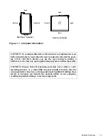
Page 13: ...lose any open application programs and files if possible CAUTION Ensure that all expansion card slots have either a card mounting bracket or a metal filler bracket installed Ensure that the unoccupied drive bays have a front panel insert installed Omitting these inserts or brackets can disturb the normal airflow in the computer resulting in possible damage to system components left side right side...

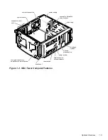
Page 14: ...puter Features microprocessor fan system board secondary hard disk drive bracket card guide assembly and primary hard disk drive power supply 3 5 inch diskette drive front bezel power button reset button hard disk drive access indicator expansion card slots drive cage drive bays typical ...

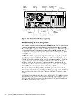
Page 15: ...sion card slots microprocessor fan system board secondary hard disk drive bracket card guide assembly and primary hard disk drive power supply drive bays typical 3 5 inch diskette drive front bezel power button reset button hard disk drive access indicator drive cage ...

Page 16: ... handled by the Device Manager which can be accessed by double clicking the System icon in the Control Panel Windows 95 documentation provides instructions on using the Device Manager to manage resources and resolve conflicts Because Dell ships only Plug and Play and PCI expansion cards on Dell Dimension systems that have a non Plug and Play operating system the ICU is not provided with systems Th...

Page 17: ... usually involves resetting jumpers on the circuit card on the under side of each drive The master slave relationship is defined in different ways for different types of drives For details about a specific drive refer to the docu mentation included with the drive When you replace a drive look at the jumpers on the removed drive to set the jumpers on the replacement drive NOTE The externally access...

Page 18: ...C power cable connectors must be connected to their corresponding power input connectors on the system board or drives in order to measure these voltages Table 1 1 DC Voltage Ranges Voltage Range Maximum Output Current 3 3 VDC 3 14 to 3 47 VDC 14 00 A1 5 VDC 4 90 to 5 25 VDC 22 00 A1 5 VDC 4 50 to 5 50 VDC 0 300 A 12 VDC 11 40 to 12 60 VDC 6 00 A2 12 VDC 10 80 to 13 20 VDC 0 300 A 5 VSB3 4 75 to 5...

Page 19: ...mation about DC power distribution Power supply cable identification Typical DC power connections for diskette tape CD ROM and hard disk drives Power distribution to sockets and connectors on the system board Pin assignments of DC power connectors Figure 1 5 DC Power Cables P1 P7 P2 P3 P6 P5 P4 ...

Page 20: ... 5 inch drives second drive uses Y cable 3 5 inch diskette drive 5 25 inch drive primary hard disk drive ISA connectors PCI connectors 1 5 V converter J6J2 J6J1 CPU system logic system board P3 P5 P4 P6 5 VSB PSON power switch GND PSON 5 VSB battery RTC GND 12 VDC GND 2 1 2 8 VDC GND KEYBRD MOUSE GND GND 5 VDC 5 VDC fuse P7 POWER J7M1 J8L1 5 25 inch drive GND 5 VDC GND GND 5 VDC USB fuse 5 VDC 5 V...

Page 21: ...r proper system operation 2 Pin 11 PSON is activated by pressing and releasing the power button while the power supply is in its standby state This action connects the power supply s PSON input to ground thereby switching the power supply to its full on condition Figure 1 7 DC Power Connector P1 11 1 PWRGOOD 1 gray 12 VDC blue 12 VDC yellow 5 VFP purple common black 2 3 4 5 6 7 8 9 10 12 13 14 15 ...

Page 22: ...nectors P2 P3 P4 P5 and P6 Figure 1 9 DC Power Connector P7 1 2 3 4 5 VDC red common black common black 12 VDC yellow P2 P3 P5 P6 1 2 3 4 5 VDC red common black common black 12 VDC yellow P4 4 5 6 3 3 VDC orange common black 3 2 1 3 3 VDC orange common black common black 3 3 VDC orange P7 ...

Page 23: ...s To use the ECC support all installed SIMMs must be parity SIMMs parallel port connector PARALLEL mouse connector MOUSE diskette drive interface connector FLOPPY power input connector POWER secondary EIDE channel connector SEC IDE ISA expansion card connectors ISA1 ISA2 and ISA3 keyboard connector KEYBRD SEC cartridge connector SLOT 1 system board jumpers primary EIDE channel connector PRI IDE PC...

Page 24: ...1 14 Dell Dimension XPS H233 and XPS H266 Systems Service Manual System Board Jumpers See Figure 1 11 and Table 1 2 for jumper settings and descriptions Figure 1 11 System Board Jumpers ...

Page 25: ...stem boots Set to pins 4 5 and boot the system to clear NVRAM Reset to pins 5 6 to restore default CMOS settings at system start up D pins 1 3 password The system and setup password features are enabled default setting The password features are disabled Set to pins 1 2 and then turn on the system to clear the password s Reset to pins 2 3 to enable password features D pins 4 6 setup Set to pins 5 6...

Page 26: ...to the parallel port requires service IRQ8 Generated by I O controller for each tick of the RTC IRQ9 Available for use by an expansion card IRQ10 Available for use by an expansion card IRQ11 Default PCI IRQ assignment IRQ12 Generated by I O controller to indicate full mouse output buffer IRQ13 Generated by math coprocessor to indicate a coprocessor error IRQ14 Generated by a device connected to th...

Page 27: ... DREQ1 Default audio DMA channel assignment DREQ2 Generated by I O controller to enable DMA cycle for attached diskette drive DREQ3 Available for use by an expansion card DREQ4 Reserved selects second DMA controller DREQ5 Available for use by an expansion card DREQ6 Available for use by an expansion card DREQ7 Available for use by an expansion card ...

Page 28: ...y speed Internal cache 32 KB Math coprocessor internal to Pentium II microprocessor with MMX technology System Information System chip set Intel 440FX PCIset Data bus width 64 bits Address bus width 32 bits DMA channels seven Interrupt levels 15 System BIOS chip 256 KB Expansion Bus Bus types ISA and PCI PCI specification complies with PCI specification 2 1 PCI bus frequency 33 MHz ISA bus frequen...

Page 29: ... tCAC 15 ns BIOS address F0000h Drive Bays Externally accessible Desktop chassis fourtotal twobaysfor5 25 inchdiskettedrives tape drives or CD ROM drives one bay for a 3 5 inchdiskettedriveortapedrive andonebay for a 3 5 inch diskette drive Mini tower chassis fivetotal twobaysfor5 25 inchdiskettedrives tape drives or CD ROM drives two bays for 3 5 inch diskette drives or tape drives and one bay fo...

Page 30: ...ine out and microphone Video 15 hole connector on video card Internally accessible Primary EIDE 40 pin connector Secondary EIDE 40 pin connector Diskette drive 34 pin connector Wave table upgrade module two 6 pin connectors CD ROM drive audio cable connector 4 pin connector Video Video type PCI video card in an expansion card slot see manufacturer s specifications Controls and Indicators Reset con...

Page 31: ... 16 7 inches Depth 44 45 cm 17 5 inches Weight 11 3 to 13 6 kg 25 to 30 lb Mini tower chassis Height 43 69 cm 17 2 inches Width 20 32 cm 8 inches Depth 44 45 cm 17 5 inches Weight 11 3 to 13 6 kg 25 to 30 lb Environmental Temperature Operating 10 to 35 C 50 to 95 F Storage 40 to 65 C 40 to 149 F Relative humidity 20 to 80 noncondensing Maximum vibration Operating 0 25 G at 3 to 200 Hz at 2 octaves...

Page 32: ...or mini tower orientation and bottom half sine pulse with a change in velocity of 50 8 cm sec 20 inches sec Storage 23 G faired square wave with a velocity change of 508 0 cm sec 200 inches sec Altitude Operating 16 to 3048 m 50 to 10 000 ft Storage 16 to 10 600 m 50 to 35 000 ft Table 1 5 Technical Specifications continued ...

Page 33: ...em or indicate the appropriate troubleshooting procedure to use After the user describes the problem follow these steps 1 Ask the user to back up any data on the hard disk drive if the system s condition permits See Maintaining the System in the online System User s Guide for informa tion about backing up data 2 Ask the user to try to duplicate the problem by repeating the operations he or she was...

Page 34: ...onnectors see Figure 1 4 For a serial mouse the mouse interface cable must be firmly attached to the serial port connector and its captive screws must be secure enough to ensure a firm connection 4 Verify that any devices attached to the serial and parallel port connec tors are properly connected Each of the serial and parallel interface cable connectors must be firmly attached to an appropriate c...

Page 35: ...utine follow these steps 1 Insert a copy of the Dell Diagnostics Diskette into drive A Turn on all peripherals and the computer If the computer is already on press the reset button or Ctrl Alt Del to reboot the system NOTE If the computer is already on save and close all open files and application programs if possible to avoid losing any data Then perform an orderly shutdown of the operating syste...

Page 36: ...tics Menu display Yes See Running the Diagnostics found later in this chapter No Proceed to step 6 6 Insert another copy of the Dell Diagnostics Diskette into the diskette drive and reboot the computer Does the Diagnostics Menu display Yes See Running the Diagnostics found later in this chapter No Remove the diagnostics diskette from the diskette drive then proceed to the next section Internal Vis...

Page 37: ...7 Reconnect the computer and any attached peripherals to their power sources and turn them on Does the problem appear to be resolved Yes No further steps are necessary No Proceed to the next section Eliminating Resource Conflicts Eliminating Resource Conflicts Devices within or connected to the computer may require dedicated memory spaces interrupt levels or DMA channels all of which must be alloc...

Page 38: ...errors are found in main memory the diagnostics loads and the Diagnos tics Menu displays This menu lets you choose the following options or exit to the MS DOS prompt Run Quick Tests Runs selected tests from all test groups to quickly locate a failure or to indicate where further testing is needed to isolate a failure Run All Tests Runs all tests for a thorough check of the system Run Specific Test...

Page 39: ...diskette based diagnostics see Running the Diagnostics in Chapter 2 POST Beep Codes If the monitor cannot display error messages during the POST the computer may emit a series of beeps that identifies the problem or that can help identify a faulty component or assembly Table 3 1 lists the beep codes that may be gener ated during POST All beep codes except beep code 8 indicate a fatal error that pr...

Page 40: ...s Defective system board 5 Microprocessor error Defective microprocessor 6 Gate A20 failure Defective system board 7 Microprocessor exception interrupt error Defective microprocessor 8 Video memory read write error System s video adapter is missing or faulty 9 ROM checksum value does not match value encoded in system BIOS Corrupted system BIOS program Defective system BIOS chip 10 NVRAM shutdown r...

Page 41: ...able Causes 8042 Gate A20 Error Gate A20 of keyboard controller is faulty Defective system board Address Line Short Address decoding not properly executed on system board Defective system board C Drive Error No response from drive C Incorrectdrivesettings in system setup program C Drive Failure Drive C failed Drive C needs reformatting Drive interface or power cable not prop erly connected Defecti...

Page 42: ...NVRAM Amount of main mem orydetectedbysystem BIOS does not match amount actually installed CMOS System Options Not Set System option parame ters in NVRAM not set One or more configu ration settings in system setup program are corrupted or im properly set CMOS Time and Date Not Set System configuration settings for time and date in system setup program appear to be incorrect System Timeand orSys te...

Page 43: ...on occurred in DMA controller Defective system board FDD Controller Failure System BIOS cannot communicate with diskette tape drive controller Defective system board HDD Controller Failure System BIOS cannot communicate with EIDE hard disk drive interface or installed hard disk drive control ler card Defective hard disk drive controller card if one is installed Defective system board Incorrect dis...

Page 44: ...e A defective KB Interface Error Error detected at key board connector Keyboard improperly connected or faulty Keyboard Error Keyboard has timing problem Keyboard improperly connected or faulty Keyboard is Locked Unlock It System cannot communicate with keyboard Keyboard improperly connected or faulty Uncorrectable ECC Error ECC detected a multiple bit error it could not correct A SIMM is faulty T...

Page 45: ...chapter read the following warning WARNING FOR YOUR PERSONAL SAFETY AND PROTECTION OF THE EQUIPMENT Before you start to work on the system perform the following steps in the sequence listed 1 Turn off the computer and any attached peripherals 2 Disconnect the computer and any attached peripherals from their power sources to reduce the potential for personal injury 3 Disconnect any telephone or tel...

Page 46: ...uter to lay flat 2 Loosen the cover mounting thumbscrew that secures the cover to the back of the computer NOTE The thumbscrew is captive and should be retained in the cover when loosened 3 Face the front of the chassis Place both hands palms down near the back corners of the cover 4 Using your index fingers push inward on the two cover release latches to release the cover 5 Slide the cover approx...

Page 47: ...Tower Chassis Figure 4 3 Front Bezel Removal Desktop Chassis To remove the front bezel follow these steps 1 Press the three tabs along the edge of the front bezel 2 Rotate the front bezel away from the chassis and disengage the retain ing hooks tabs 3 front bezel tabs 3 front bezel ...

Page 48: ...ne System User s Guide Front Panel Insert Figure 4 4 Front Panel Insert Removal The front panel inserts are attached to the drive cage Any empty bay should have a front panel insert installed To remove a front panel insert follow these steps 1 Remove the front bezel 2 Press the two tabs on the right side of the front panel insert 3 Rotate the right side of the front panel insert outward to disenga...

Page 49: ...cage first remove the drive cage from the chassis as follows 1 Remove the front bezel 2 Note the location and orientation of all cables attached to drives installed in the drive cage Then disconnect the cables 3 Remove the screw that secures the drive cage to the chassis 4 Slide the drive cage forward approximately one half inch Then lift it up and away from the chassis The side of the chassis con...

Page 50: ... the front bezel 2 Remove the drive cage and drives as an assembly 3 Remove the three drive mounting screws and slide the drive out of the bay When you replace a drive be sure to set the jumpers on the replacement drive the same as the jumpers on the drive you removed For additional information about jumper settings on EIDE drives see EIDE Subsystem in Chapter 1 drive mounting screws 3 ...

Page 51: ...unting screws and slide the drive assembly out of the bay 4 Remove the two drive bracket mounting screws and remove the drive bracket from the drive If you are working on a desktop chassis the small plastic filler panel remains in place on the front face of the drive bracket When you replace a drive be sure to set the jumpers on the replacement drive the same as the jumpers on the drive you remove...

Page 52: ...3 5 inch drive bay follow these steps 1 Remove the front bezel 2 Remove the drive cage and drives as an assembly 3 Remove the three drive mounting screws from the left side and bottom of the drive cage and slide the drive out of the drive cage When you replace a drive be sure to set the jumpers on the replacement drive the same as the jumpers on the drive you removed For additional information abo...

Page 53: ...tte drive follow these steps 1 Remove the front bezel 2 Disconnect the power and interface cables from the back of the 3 5 inch diskette drive 3 Press the two drive release tabs and slide the drive out of the bay Transfer the drive release tabs to the replacement diskette drive before install ing the new drive drive release tabs ...

Page 54: ...de assembly 4 Disconnect the power and interface cables from the back of the primary hard disk drive When you reinstall the primary hard disk drive be sure the circuit board is toward the front of the chassis When you replace a hard disk drive be sure to set the jumpers on the replace ment drive the same as the jumpers on the drive you removed For additional information about jumper settings on EI...

Page 55: ...drive follow these steps 1 Remove the front bezel 2 Disconnect the power and interface cables from the back of the second ary hard disk drive 3 Remove the two drive assembly mounting screws 4 Slide the secondary hard disk drive assembly toward the back of the chassis and lift it out secondary hard disk drive assembly drive assembly mounting screws 2 ...

Page 56: ...isk Drive Removal When you replace a hard disk drive be sure to set the jumpers on the replace ment drive the same as the jumpers on the drive you removed For additional information about jumper settings on EIDE drives see EIDE Subsystem in Chapter 1 When you insert the replacement hard disk drive into the drive bracket be sure the two tabs on the bracket fit into the mounting holes on the side of...

Page 57: ...wer cable at the power supply 2 Disconnect the DC power cables from the POWER and J7M1 connec tors on the system board see Figure 4 17 3 Disconnect the DC power cables from all the drives 4 Remove the two power supply mounting screws from the back of the chassis 5 Lift the power supply out of the chassis power supply power supply mounting screws 2 ...

Page 58: ...follow these steps 1 Disconnect the microprocessor fan cable from the J8L1 connector on the system board see Figure 4 17 2 At the back of the chassis press the two release buttons and lift the microprocessor fan assembly out of the chassis Maintain upward pressure on the fan assembly while you press the two release buttons microprocessor fan assembly release buttons back of chassis ...

Page 59: ...n cards before disconnecting these cables 2 Remove the 3 5 inch diskette drive 3 Remove the primary hard disk drive 4 If a secondary hard disk drive assembly is present remove it 5 Disconnect the control panel cable from connector J9D1 on the system board see Figure 4 17 6 Press the four mounting tabs that secure the card guide assembly to the front panel and press on the tab at the back of the ca...

Page 60: ...Panel Board Removal To remove the control panel board follow these steps 1 Remove the front bezel 2 Remove the card guide assembly 3 Press the mounting tab to release the control panel board from the card guide assembly and remove the control panel board card guide assembly control panel board mounting tab ...

Page 61: ...onnectors ISA1 ISA2 and ISA3 keyboard connector KEYBRD SEC cartridge connector SLOT 1 system board jumpers primary EIDE channel connector PRI IDE PCI expansion card connectors PCI1 PCI2 PCI3 and PCI4 control panel connector J9D1 battery socket BT9M1 serial port connector SER1 SIMM sockets J6J1 J6J2 J7J1 and J7J2 microprocessor fan connector J8L1 wave table upgrade connectors J7C1 and J7D1 SCSI har...

Page 62: ...cation of each connector and the orientation of any cables attached to the expansion card before disconnecting these cables 2 Remove the retaining screw from the card mounting bracket 3 Grasp the expansion card by its corners and carefully pull it out of its expansion card connector card mounting bracket card guide assembly ISA expansion card front of computer expansion card connector card edge co...

Page 63: ... steps 2 and 3 of Figure 4 19 until it is released from its socket To replace a SIMM position it in its socket as shown in step 1 of Figure 4 20 While holding the SIMM s edge connector firmly against the SIMM socket rotate it in the direction of the arrows shown in step 2 of the figure until it snaps into place Figure 4 20 SIMM Replacement cutout back of computer 1 2 3 edge connector back of compu...

Page 64: ...EC cartridge from the connector 4 Pull out the cartridge release latches until they snap into place To install the replacement SEC cartridge and heat sink assembly first verify that the cartridge release latches are pulled out Then slide the SEC cartridge into the guide bracket assembly with the heat sink toward the front of the computer and WARNING The SEC cartridge and heat sink can get extremel...

Page 65: ...by prying it out of its socket with your fingers or a blunt nonconductive object such as a plastic screwdriver To replace the battery install the new battery with the side facing up Then start the system setup program and reset the System Date and System Time categories Compare the system configuration settings with the copy made in step 1 Restore any system configuration information that was lost...

Page 66: ...ere is a secondary hard disk drive remove it 5 Disconnect all internal cables from the system board The cables attached to the PRI IDE SEC IDE and FLOPPY connectors see Figure 4 18 each have two latches securing them to the system board Press the latch on each end of the cable connector and pull to release the cable from the system board 6 Remove the screws that secure the system board to the chas...

Page 67: ...nd heat sink assembly is more accessible when the sys tem board has been removed from the chassis but it is necessary to stabilize the board due to the forces required to remove components 10 Remove the guide bracket assembly for the SEC cartridge NOTE The four nuts are captive and should be retained in the assembly when loosened Using a 2 Phillips screwdriver loosen each of the four nuts see Figu...

Page 68: ...r the SIMMs to the new system board and set the configuration jumpers to match the old sys tem board When installing the new system board in the computer push the system board against the back of the chassis so that the system board makes firm contact with the I O gasket to prevent EMI leakage CAUTION Failure to install the system board exactly as described may result in EMI leakage that could int...

Page 69: ...he documentation that accompanied the operating system System Setup Screens The system setup program consists of a number of menus and submenus with configuration options and information The menu bar provides access to the fol lowing five screens Main screen Provides settings for the basic system configuration Advanced screen Provides detailed settings for some system features Security screen Prov...

Page 70: ...skette drive in your computer Primary IDE Master Identifies the first drive attached to the primary EIDE interface usually the boot hard disk drive See the Device Configuration Sub menu subsection in this appendix Primary IDE Slave Identifies the second drive attached to the primary EIDE interface usually a second hard disk drive See the Device Configuration Submenu subsection in this appendix Sec...

Page 71: ...plays the video mode detected by the system Base Memory Displays the maximum amount of memory available to MS DOS programs that do not use expanded or extended memory To change the amount of base memory see the Chipset Configuration Submenu subsection in this appendix Extended Memory Displays the amount of system memory available as extended memory Service Tag Displays system s service tag number ...

Page 72: ...ss you are using a hard disk drive that does not support the autodetect fea ture In this case select User Definable and enter the appropriate values in the Cylinders Heads Sectors and Maximum Capacity fields For a non IDE drive set this category to Disabled Fast Programmed I O Modes Enables or disables the use of programmed I O which can improve the performance of a hard disk drive If you select A...

Page 73: ...hannel CD ROM A CD ROM drive Network A drive on the network server Disabled First boot device not available Second Boot Device Determines which device the system tries to boot from if it cannot boot from the device selected for First Boot Device Options for this category are the same as for the First Boot Device Third Boot Device Determines which device the system tries to boot from if it cannot b...

Page 74: ...che memory Num Lock Determines whether keyboard s Num Lock mode is activated at boot Floppy Access Determines whether your system can write data to a diskette inserted in a diskette drive Options are Read Write and Read Only Setup Prompt Enables the default or disables the prompt to enter the system setup program during the boot routine Hard Disk Pre Delay Enables or disables the default a delay b...

Page 75: ...he microprocessor Cache Size Indicates the amount of secondary cache mem ory installed Peripheral Configuration Displays a submenu See the Peripheral Configuration Submenu subsection in this appendix Chipset Configuration Displays a submenu See the Chipset Config uration Submenu subsection in this appendix Plug and Play Configuration Displays a submenu See the Plug and Play Configuration Submenu s...

Page 76: ... this category are Auto Configured the default and Disabled Floppy Interface Configures the diskette tape drive interface on the system board Options for this category are Auto Configured the default Enabled which locks the interface at I O port address 3F0h 3F5h and Disabled Serial Port 1 Interface Configures the built in serial port on the sys tem board You can set this category to Auto Configur...

Page 77: ...his cate gory is set to Enabled the system dynamically allocates an IRQ for the USB connectors according to the PCI specification Audio Interface Determines whether the integrated audio con troller is Enabled the default or Disabled Set this category to Disabled to use a sound expansion card instead of the integrated audio controller Primary PCI IDE Status Indicates whether the primary EIDE interf...

Page 78: ...tended memory Options for this category are 640 KB the default and 512 KB Latency Timer PCI Clocks Specifies how quickly a PCI card is guaranteed to have access to the PCI bus The value for this category can be set to Auto Configured the default or to a specific PCI clock cycle value in increments of eight from 16 to 128 Bank 0 Indicates the type of SIMMs installed in the first pair of SIMM socket...

Page 79: ...her categories are displayed on the Plug and Play Configuration submenu If Configuration Mode is set to Use BIOS Setup the ISA Shared Memory Size and IRQ catego ries are available If Use PnP OS is selected the PnP OS category appears ISA Shared Memory Size ISA Shared Memory Size specifies the size of the shared memory range for ISA expansion cards Options are Disabled 16KB 32KB 48KB 64KB 80KB and ...

Page 80: ...e or clear a system password NOTE The system password cannot be assigned changed or cleared if the Password Status category is set to Locked Enter Setup Password Allows you to assign change or clear a setup password The setup password can be used both to gain access to the computer system and to make changes in the system setup program Password Status NOTE Some computer systems do not display this...

Page 81: ...wer screen IDE Drive Power Down When set to Enabled the default IDE Drive Power Down allows most EIDE hard disk drives to automatically switch into low power mode after a specified period of system inactivity called a time out The time out period is set with the Inactivity Timer category When the IDE Drive Power Down category is set to Disabled hard disk drives do not switch into low power mode ...

Page 82: ...power saved are Standby 20 power saved the default Suspend 90 power saved Sleep 95 power saved The higher the percentage of monitor power saved the longer the monitor takes to return to full power when the time out period ends Inactivity Timer Determines the period of system inactivity before certain system components enter a low power mode To disable power management set this field to 0 Hot Key A...

Page 83: ...nges you have made exits the system setup program and restarts the system Load Setup Defaults Discards any changes you have made reverts all categories to their original default settings but does not exit the system setup program Discard Changes Discards any changes you have made reverts all categories to their last saved settings but does not exit the system setup program Save Changes Saves any c...

Page 84: ...A 16 Dell Dimension XPS H233 and XPS H266 Systems Service Manual ...

Page 85: ...4 orientation 1 3 specifications 1 18 connectors back panel 1 6 system board 1 13 control panel board removal 4 16 cover removal 4 2 D DC power connector pin assignments 1 11 diagram 1 10 distribution 1 9 diagnostics 2 6 diskette drive removal 4 9 DMA channel assignments 1 17 drive cage location desktop 1 4 location mini tower 1 5 removal 4 5 drives 3 5 inch diskette removal 4 9 5 25 inch removal ...

Page 86: ...1 16 ISA expansion card slots 1 6 J jumpers 1 14 K key to enter system setup program A 1 M main memory 1 13 microprocessor removal 4 20 microprocessor fan assembly removal 4 14 P PCI expansion card slots 1 6 POST beep codes 3 2 power AC power receptacle 1 6 connector pin assignments 1 11 DC power diagram 1 10 DC power distribution 1 9 voltage selection switch 1 6 power supply about 1 8 location de...

Page 87: ... A 10 entering A 1 Exit screen A 15 IDE Device Configuration submenu A 4 Main screen A 2 menus A 1 system setup program continued Peripheral Configuration submenu A 8 Plug and Play Configuration submenu A 11 Power screen A 13 Security screen A 12 T technical specifications 1 18 troubleshooting boot routine 2 3 diskette based diagnostics 2 6 external visual inspection 2 2 getting help 2 6 initial p...

Page 88: ......

Page 89: ... Printed in the U S A P N 84980 ...

Reviews: