background image

Dell Inspiron M4040/

14-N4050 Owner’s Manual

Regulatory model: P22G             Regulatory type: P22G001; P22G002

Summary of Contents for Inspiron 3420

Page 1: ...Dell Inspiron M4040 14 N4050 Owner s Manual Regulatory model P22G Regulatory type P22G001 P22G002 ...

Page 2: ...ct to change without notice 2011 Dell Inc All rights reserved Trademarks used in this text Dell the DELL logo and Inspiron are trademarks of Dell Inc Bluetooth is a registered trademark owned by Bluetooth SIG Inc Microsoft Windows and the Windows start button logo are either trademarks or registered trademarks ofMicrosoft Corporation in the United States and or other countries Reproduction of thes...

Page 3: ...e Working Inside Your Computer 10 2 Battery 13 Removing the Battery 13 Replacing the Battery 14 3 Keyboard 15 Removing the Keyboard 15 Replacing the Keyboard 17 4 Memory Module s 19 Removing the Memory Module s 19 Replacing the Memory Module s 20 5 Optical Drive 23 Removing the Optical Drive 23 ...

Page 4: ...ssembly 28 7 Power Button Board 31 Removing the Power Button Board 31 Replacing the Power Button Board 32 8 Hard Drive 33 Removing the Hard Drive 33 Replacing the Hard Drive 35 9 Wireless Mini Card 37 Removing the Mini Card 37 Replacing the Mini Card 38 10 Audio Board 41 Removing the Audio Board 41 Replacing the Audio Board 42 ...

Page 5: ... the USB Board 48 13 Thermal Cooling Assembly 49 Removing the Thermal Cooling Assembly 49 Replacing the Thermal Cooling Assembly 50 14 Processor Module For Inspiron 14 N4050 Only 51 Removing the Processor Module 51 Replacing the Processor Module 52 15 Hinge Cover 55 Removing the Hinge Cover 55 Replacing the Hinge Cover 57 16 Display 59 Display Assembly 59 ...

Page 6: ...el 62 Replacing the Display Bezel 63 Removing the Display Panel 63 Replacing the Display Panel 66 17 Camera Module 69 Removing the Camera Module 69 Replacing the Camera Module 70 18 System Board 73 Removing the System Board 73 Replacing the System Board 75 Entering the Service Tag in the BIOS 76 19 Flashing the BIOS 77 ...

Page 7: ...Contents 7 ...

Page 8: ...8 Contents ...

Page 9: ...ols The procedures in this document may require the following tools Small flat blade screwdriver Phillips screwdriver Plastic scribe BIOS executable update program available at support dell com Turning Off Your Computer CAUTION To avoid losing data save and close all open files and exit all open programs before you turn off your computer 1 Save and close all open files and exit all open programs 2...

Page 10: ...authorized by Dell is not covered by your warranty CAUTION When you disconnect a cable pull on its connector or on its pull tab not on the cable itself Some cables have connectors with locking tabs if you are disconnecting this type of cable press in on the locking tabs before you disconnect the cable As you pull connectors apart keep them evenly aligned to avoid bending any connector pins Also be...

Page 11: ... prevent damage to the system board remove the main battery see Removing the Battery on page 13 before working inside the computer 7 Remove the battery see Removing the Battery on page 13 8 Turn the computer top side up open the display and press the power button to ground the system board ...

Page 12: ...12 Before You Begin ...

Page 13: ...electrostatic discharge ground yourself by using a wrist grounding strap or by periodically touching an unpainted metal surface such as a connector on your computer CAUTION To avoid damage to the computer use only the battery designed for this particular Dell computer Do not use batteries designed for other Dell computers Removing the Battery 1 Follow the instructions in Before You Begin on page 9...

Page 14: ... Follow the instructions in Before You Begin on page 9 2 Slide the battery into the battery bay until it clicks into place 3 Slide the battery lock latch to the lock position 1 battery release latch 2 battery 3 battery lock latch 1 2 3 ...

Page 15: ...riodically touching an unpainted metal surface such as a connector on your computer CAUTION To help prevent damage to the system board remove the main battery see Removing the Battery on page 13 before working inside the computer Removing the Keyboard 1 Follow the instructions in Before You Begin on page 9 2 Remove the battery see Removing the Battery on page 13 CAUTION The keycaps on the keyboard...

Page 16: ...ult in scratching the display panel 5 Without pulling hard on the keyboard hold it towards the display 6 Lift the connector latch that secures the keyboard cable to the connector on the system board and remove the keyboard cable 7 Lift the keyboard off the computer 1 plastic scribe 2 tabs 4 3 keyboard 2 1 3 ...

Page 17: ...connector latch to secure the keyboard cable to the connector on the system board 3 Slide the tabs on the keyboard into the slots on the palm rest 4 Gently press around the edges of the keyboard to lock the four tabs securing the keyboard 5 Close the display and turn the computer over 6 Replace the battery see Replacing the Battery on page 14 1 keyboard cable 2 keyboard 1 2 ...

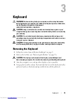
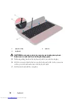
Page 18: ...18 Keyboard ...

Page 19: ...e the computer You can increase your computer memory by installing memory modules on the system board For information on the type of memory supported by your computer see the Specifications at support dell com manuals NOTE Memory modules purchased from Dell are covered under your computer warranty Your computer has two user accessible SODIMM sockets labeled DIMM A and DIMM B that can be accessed f...

Page 20: ...n Before You Begin on page 9 2 Align the notch in the memory module with the tab in the memory module connector 3 Slide the memory module firmly into the slot at a 45 degree angle and press the memory module down until it clicks into place If you do not hear the click remove the memory module and reinstall it NOTE If the memory module is not installed properly the computer may not boot 1 memory mo...

Page 21: ... connect the AC adapter to your computer and an electrical outlet 6 Turn on the computer As the computer boots it detects the memory module s and automatically updates the system configuration information To confirm the amount of memory installed in the computer Click Start Control Panel System and Security System 1 tab 2 notch 1 2 ...

Page 22: ...22 Memory ...

Page 23: ... wrist grounding strap or by periodically touching an unpainted metal surface such as a connector on your computer CAUTION To help prevent damage to the system board remove the main battery see Removing the Battery on page 13 before working inside the computer Removing the Optical Drive 1 Follow the instructions in Before You Begin on page 9 2 Remove the battery see Removing the Battery on page 13...

Page 24: ...crew that secures the optical drive to the computer base 4 Replace the keyboard see Replacing the Keyboard on page 17 5 Replace the battery see Replacing the Battery on page 14 CAUTION Before turning on the computer replace all screws and ensure that no stray screws remain inside the computer Failure to do so may result in damage to the computer 1 plastic scribe 2 screw 3 optical drive 4 notch 1 2...

Page 25: ...rized by Dell is not covered by your warranty CAUTION To avoid electrostatic discharge ground yourself by using a wrist grounding strap or by periodically touching an unpainted metal surface such as a connector on your computer CAUTION To help prevent damage to the system board remove the main battery see Removing the Battery on page 13 before working inside the computer Removing the Palm Rest Ass...

Page 26: ...move the three screws on the palm rest assembly CAUTION Pull on the plastic tab on top of the connectors to avoid damaging the connectors 6 Lift the connector latch that secures the power button board cable and touch pad cable to the connectors on the system board and remove the cables ...

Page 27: ...computer base to avoid damage to the palm rest 7 Using a plastic scribe carefully pry out the palm rest assembly and then ease the palm rest assembly from the computer base 8 Lift the palm rest assembly off the computer base 1 power button board cable 2 touch pad cable 1 2 ...

Page 28: ...e palm rest assembly on the computer base and gently snap the palm rest assembly into place 4 Slide the touch pad cable and power button board cable into the connectors on the system board and press down on the connector latches to secure them 5 Replace the three screws on the palm rest assembly 6 Replace the keyboard see Replacing the Keyboard on page 17 7 Replace the eight screws that secure the...

Page 29: ...eplace the battery see Replacing the Battery on page 14 CAUTION Before turning on the computer replace all screws and ensure that no stray screws remain inside the computer Failure to do so may result in damage to the computer ...

Page 30: ...30 Palm Rest Assembly ...

Page 31: ...surface such as a connector on your computer CAUTION To help prevent damage to the system board remove the main battery see Removing the Battery on page 13 before working inside the computer Removing the Power Button Board 1 Follow the instructions in Before You Begin on page 9 2 Remove the battery see Removing the Battery on page 13 3 Follow the instructions from step 3 to step 8 in Removing the ...

Page 32: ...ton board to the palm rest 4 Slide the power button board cable through the slot on the palm rest assembly 5 Turn the palm rest assembly over 6 Follow the instructions from step 3 to step 7 in Replacing the Palm Rest Assembly on page 28 7 Replace the battery see Replacing the Battery on page 14 CAUTION Before turning on the computer replace all screws and ensure that no stray screws remain inside ...

Page 33: ...mputer CAUTION To help prevent damage to the system board remove the main battery see Removing the Battery on page 13 before working inside the computer CAUTION To prevent data loss turn off your computer see Turning Off Your Computer on page 9 before removing the hard drive assembly Do not remove the hard drive while the computer is On or in Sleep state CAUTION Hard drives are extremely fragile E...

Page 34: ...isconnect it from the connector on the system board 5 Lift the hard drive assembly out of the computer base 6 Remove the two screws that secure the hard drive bracket to the hard drive 7 Lift the hard drive bracket away from the hard drive 1 hard drive assembly 1 ...

Page 35: ...rive 5 Place the hard drive assembly on the computer base 6 Push the hard drive assembly towards the right to connect it to the connector on the system board 7 Follow the instructions from step 3 to step 7 in Replacing the Palm Rest Assembly on page 28 8 Replace the battery see Replacing the Battery on page 14 CAUTION Before turning on the computer replace all screws and ensure that no stray screw...

Page 36: ...36 Hard Drive ...

Page 37: ...ve the main battery see Removing the Battery on page 13 before working inside the computer NOTE Dell does not guarantee compatibility or provide support for Mini Cards from sources other than Dell If you ordered a wireless Mini Card with your computer the card is already installed Your computer has one half Mini Card slot for Wireless Local Area Network WLAN Bluetooth combo card NOTE Depending on ...

Page 38: ... store it in protective antistatic packaging For more information see Protecting Against Electrostatic Discharge in the safety information that shipped with your computer Replacing the Mini Card 1 Follow the instructions in Before You Begin on page 9 2 Remove the new Mini Card from its packaging 1 Mini Card antenna cables 2 2 tab 1 2 ...

Page 39: ...Mini Card you are installing The following table provides the antenna cable color scheme for the Mini Cards supported by your computer 6 Follow the instructions from step 3 to step 7 in Replacing the Palm Rest Assembly on page 28 7 Replace the battery see Replacing the Battery on page 14 CAUTION Before turning on the computer replace all screws and ensure that no stray screws remain inside the com...

Page 40: ...40 Wireless Mini Card ...

Page 41: ... not covered by your warranty CAUTION To help prevent damage to the system board remove the main battery see Removing the Battery on page 13 before working inside the computer Removing the Audio Board 1 Follow the instructions in Before You Begin on page 9 2 Remove the battery see Removing the Battery on page 13 3 Follow the instructions from step 3 to step 8 in Removing the Palm Rest Assembly on ...

Page 42: ...e the audio board cable to the connector on the system board 4 Connect the Mini Card antenna cables to the connectors on the Mini Card see Replacing the Mini Card on page 38 5 Follow the instructions from step 3 to step 7 in Replacing the Palm Rest Assembly on page 28 6 Replace the battery see Replacing the Battery on page 14 CAUTION Before turning on the computer replace all screws and ensure tha...

Page 43: ...g an unpainted metal surface such as a connector on your computer CAUTION To help prevent damage to the system board remove the main battery see Removing the Battery on page 13 before working inside the computer Removing the Coin Cell Battery 1 Follow the instructions in Before You Begin on page 9 2 Remove the battery see Removing the Battery on page 13 3 Follow the instructions from step 3 to ste...

Page 44: ...astic scribe gently pry the coin cell out of the battery socket on the system board b Lift the coin cell battery out of the battery socket on the system board 1 battery socket 2 coin cell battery 3 coin cell battery cable 4 audio board cable 4 3 2 1 1 2 ...

Page 45: ...the connector on the system board c Slide the audio board cable into the connector on the system board Press down on the connector latch to secure the audio board cable to the connector on the system board 2 Follow the instructions from step 3 to step 7 in Replacing the Palm Rest Assembly on page 28 3 Replace the battery see Replacing the Battery on page 14 CAUTION Before turning on the computer r...

Page 46: ...46 Coin Cell Battery ...

Page 47: ...ur warranty CAUTION To help prevent damage to the system board remove the main battery see Removing the Battery on page 13 before working inside the computer Removing the USB Board 1 Follow the procedures in Before You Begin on page 9 2 Remove the battery see Removing the Battery on page 13 3 Follow the instructions from step 3 to step 8 in Removing the Palm Rest Assembly on page 25 4 Remove the o...

Page 48: ... on the system board Press down on the connector latch to secure the USB board cable to the connector on the system board 5 Replace the optical drive see Replacing the Optical Drive on page 24 6 Follow the instructions from step 3 to step 7 in Replacing the Palm Rest Assembly on page 28 7 Replace the battery see Replacing the Battery on page 14 CAUTION Before turning on the computer replace all sc...

Page 49: ...ce such as a connector on your computer CAUTION To help prevent damage to the system board remove the main battery see Removing the Battery on page 13 before working inside the computer NOTE Based on the selection you made at the time of purchase of your computer location of the fan cable and dimensions of the thermal cooling assembly may vary Removing the Thermal Cooling Assembly 1 Follow the ins...

Page 50: ... cooling assembly to the system board 4 Connect the fan cable to the connector on the system board 5 Follow the instructions from step 3 to step 7 in Replacing the Palm Rest Assembly on page 28 6 Replace the battery see Replacing the Battery on page 14 CAUTION Before turning on the computer replace all screws and ensure that no stray screws remain inside the computer Failure to do so may result in...

Page 51: ...revent damage to the system board remove the main battery see Removing the Battery on page 13 before working inside the computer CAUTION Handle components and cards by their edges and avoid touching pins and contacts Removing the Processor Module 1 Follow the instructions in Before You Begin on page 9 2 Remove the battery see Removing the Battery on page 13 3 Follow the instructions from step 3 to...

Page 52: ...r module 6 Lift the processor module from the ZIF socket Replacing the Processor Module 1 Follow the instructions in Before You Begin on page 9 NOTE If you install a new processor a new thermal assembly including an affixed thermal pad or a new thermal pad along with documentation to illustrate proper installation is shipped 1 ZIF socket 2 ZIF socket cam screw 1 2 ...

Page 53: ... not seated properly CAUTION To avoid damage to the processor hold the screwdriver perpendicular to the processor when turning the cam screw 3 Tighten the ZIF socket by turning the cam screw clockwise to secure the processor module to the system board 4 Replace the thermal cooling assembly see Replacing the Thermal Cooling Assembly on page 50 5 Follow the instructions from step 3 to step 7 in Repl...

Page 54: ...54 Processor Module For Inspiron 14 N4050 Only ...

Page 55: ...orized by Dell is not covered by your warranty CAUTION To avoid electrostatic discharge ground yourself by using a wrist grounding strap or by periodically touching an unpainted metal surface such as a connector on your computer CAUTION To help prevent damage to the system board remove the main battery see Removing the Battery on page 13 before working inside the computer Removing the Hinge Cover ...

Page 56: ...56 Hinge Cover 4 Turn the computer over 5 Pry the hinge cover off the computer base 1 ...

Page 57: ...snap the hinge cover into place 3 Turn the computer over 4 Replace the two screws that secure the hinge cover to the computer base 5 Replace the battery see Replacing the Battery on page 14 CAUTION Before turning on the computer replace all screws and ensure that no stray screws remain inside the computer Failure to do so may result in damage to the computer 1 hinge cover ...

Page 58: ...58 Hinge Cover ...

Page 59: ...age to the system board remove the main battery see Removing the Battery on page 13 before working inside the computer Display Assembly Removing the Display Assembly 1 Follow the instructions in Before You Begin on page 9 2 Remove the battery see Removing the Battery on page 13 3 Follow the instructions from step 3 to step 8 in Removing the Palm Rest Assembly on page 25 4 Remove the optical drive ...

Page 60: ...lay 10 Remove the two screws that secure the display assembly to the computer base 11 Lift and remove the display assembly out of the computer base 1 display cable 2 Mini Card 3 Mini Card antenna cables 1 3 2 ...

Page 61: ...the display cable and Mini Card antenna cables through the routing guides 4 Connect the display cable to the connector on the system board 5 Connect the Mini Card antenna cables to the Mini Card 6 Replace the hinge cover see Replacing the Hinge Cover on page 57 7 Replace the USB board see Replacing the USB Board on page 48 8 Replace the optical drive see Replacing the Optical Drive on page 24 1 di...

Page 62: ...inside the computer Failure to do so may result in damage to the computer Display Bezel Removing the Display Bezel 1 Follow the instructions in Before You Begin on page 9 2 Remove the display assembly see Removing the Display Assembly on page 59 CAUTION The display bezel is extremely fragile Be careful when removing it to prevent damaging the display bezel 3 Using your fingertips carefully pry up ...

Page 63: ...damage to the computer Display Panel Removing the Display Panel 1 Follow the instructions in Before You Begin on page 9 2 Remove the display assembly see Removing the Display Assembly on page 59 3 Remove the display bezel see Removing the Display Bezel on page 62 4 Disconnect the camera cable from the connector on the camera module see Removing the Camera Module on page 69 5 Make a note of the dis...

Page 64: ...Display 7 Remove the four screws two on each side that secure the display panel brackets to the display panel 1 display cable 2 display cover 3 display panel 4 Mini Card antenna cables 5 screws 6 5 4 1 2 3 ...

Page 65: ...ean surface 9 Lift the tape that secures the display cable to the display board connector and disconnect the display cable 10 Make a note of the display cable routing and peel the cable from the back of the display panel 1 screws 4 2 display panel brackets 2 1 2 ...

Page 66: ... replace the four screws two on each side 6 Align the screw holes on the display panel with the screw holes on the display cover and replace the six screws 7 Route the display cable and Mini Card antenna cables through the routing guides on the display hinges 8 Connect the camera cable to the connector on the camera module see Replacing the Camera Module on page 70 9 Replace the display bezel see ...

Page 67: ...Display 67 CAUTION Before turning on the computer replace all screws and ensure that no stray screws remain inside the computer Failure to do so may result in damage to the computer ...

Page 68: ...68 Display ...

Page 69: ...board remove the main battery see Removing the Battery on page 13 before working inside the computer Removing the Camera Module 1 Follow the instructions in Before You Begin on page 9 2 Remove the battery see Removing the Battery on page 13 3 Follow the instructions from step 3 to step 8 in Removing the Palm Rest Assembly on page 25 4 Remove the optical drive see Removing the Optical Drive on page...

Page 70: ... cover to place the camera module in position and snap the camera module into place 4 Replace the display bezel see Replacing the Display Bezel on page 63 5 Replace the display assembly see Replacing the Display Assembly on page 61 6 Replace the hinge cover see Replacing the Hinge Cover on page 57 7 Replace the USB board see Replacing the USB Board on page 48 1 camera module 2 camera cable 3 tabs ...

Page 71: ...uctions from step 3 to step 7 in Replacing the Palm Rest Assembly on page 28 10 Replace the battery see Replacing the Battery on page 14 CAUTION Before turning on the computer replace all screws and ensure that no stray screws remain inside the computer Failure to do so may result in damage to the computer ...

Page 72: ...72 Camera Module ...

Page 73: ...he system board remove the main battery see Removing the Battery on page 13 before working inside the computer CAUTION Handle components and cards by their edges and avoid touching pins and contacts Removing the System Board 1 Follow the instructions in Before You Begin on page 9 2 Press and eject any installed cards from the 3 in 1 media card reader 3 Remove the battery see Removing the Battery o...

Page 74: ...ctors on the system board 13 Remove the two screws that secure the system board to the computer base 14 Lift the system board at an angle and release the connectors on the system board from the slots on the computer base NOTE Based on the selection you made at the time of purchase of your computer the dimensions of the system board and the location of the system board components may vary 1 display...

Page 75: ...ble speakers cable audio board cable USB board cable coin cell battery cable and AC adapter cable to the connectors on the system board 5 Replace the processor see Replacing the Processor Module on page 52 6 Replace the thermal cooling assembly see Replacing the Thermal Cooling Assembly on page 50 7 Follow the instructions from step 5 to step 6 in Replacing the Hard Drive on page 35 8 Replace the ...

Page 76: ...rning on the computer replace all screws and ensure that no stray screws remain inside the computer Failure to do so may result in damage to the computer 15 Turn on the computer NOTE After you have replaced the system board enter the computer Service Tag into the BIOS of the replacement system board 16 Enter the service tag see Entering the Service Tag in the BIOS on page 76 Entering the Service T...

Page 77: ...s Service Tag a Click Select Model b Select the type of product in the Select Your Product Family list c Select the product brand in the Select Your Product Line list d Select the product model number in the Select Your Product Model list NOTE If you have selected a different model and want to start over again click Start Over on the top right of the menu e Click Confirm 4 A list of results appear...

Page 78: ...78 Flashing the BIOS 8 Double click the file icon on the desktop and follow the instructions on the screen ...

Reviews: