background image

Inspiron 3472
Service Manual

Computer Model: Inspiron 3472
Regulatory Model: D14S
Regulatory Type: D14S003

Summary of Contents for Inspiron 3472

Page 1: ...Inspiron 3472 Service Manual Computer Model Inspiron 3472 Regulatory Model D14S Regulatory Type D14S003 ...

Page 2: ...amage to hardware or loss of data and tells you how to avoid the problem WARNING A WARNING indicates a potential for property damage personal injury or death 2018 Dell Inc or its subsidiaries All rights reserved Dell EMC and other trademarks are trademarks of Dell Inc or its subsidiaries Other trademarks may be trademarks of their respective owners 2018 02 Rev A00 ...

Page 3: ...e your computer 12 Technical overview 13 System board components 14 Removing the computer cover 16 Procedure 16 Replacing the computer cover 17 Procedure 17 Removing the front bezel 18 Prerequisites 18 Procedure 18 Replacing the front bezel 21 Procedure 21 Post requisites 21 Removing the 2 5 inch hard drive 22 Prerequisites 22 Procedure 23 3 ...

Page 4: ... hard drive 31 Procedure 31 Post requisites 31 Removing the optical drive 32 Prerequisites 32 Procedure 32 Replacing the optical drive 35 Procedure 35 Post requisites 35 Removing the memory module 36 Prerequisites 36 Procedure 37 Replacing the memory module 39 Procedure 39 Post requisites 39 Removing the coin cell battery 40 Prerequisites 40 Procedure 40 4 ...

Page 5: ...cedure 46 Post requisites 47 Removing the antenna modules 48 Prerequisites 48 Procedure 48 Replacing the antenna modules 50 Procedure 50 Post requisites 50 Removing the power button module 51 Prerequisites 51 Procedure 51 Replacing the power button module 54 Procedure 54 Post requisites 54 Removing the thermal cooling assembly 55 Prerequisites 55 Procedure 55 5 ...

Page 6: ...dio driver 64 Downloading the graphics driver 65 Downloading the USB driver 65 Downloading the chipset driver 66 Downloading the network driver 67 System setup 69 Boot Sequence 69 Navigation keys 69 BIOS overview 70 Entering BIOS setup program 70 System Setup Options 71 Flashing the BIOS 76 Troubleshooting 77 Flashing the BIOS 77 Reinstall Windows using a USB recovery drive 77 Enhanced Pre Boot Sy...

Page 7: ...Running the ePSA diagnostics 79 Diagnostics 79 Flea power release 80 Wi Fi power cycle 80 Getting help and contacting Dell 81 Self help resources 81 Contacting Dell 82 7 ...

Page 8: ...nd monitor from your computer 5 Remove any media card and optical disc from your computer if applicable 6 After the computer is unplugged press and hold the power button for 5 seconds to ground the system board Safety instructions Use the following safety guidelines to protect your computer from potential damage and ensure your personal safety WARNING Before working inside your computer read the s...

Page 9: ...an unpainted metal surface such as the metal at the back of the computer While you work periodically touch an unpainted metal surface to dissipate static electricity which could harm internal components CAUTION When you disconnect a cable pull on its connector or on its pull tab not on the cable itself Some cables have connectors with locking tabs or thumb screws that you must disengage before dis...

Page 10: ...rew image Computer cover Chassis 6 32xL6 35 2 2 5 inch hard drive Drive cage 6 32xL3 6 1 2 5 inch hard drive Hard drive bracket M3xL3 5 4 3 5 inch hard drive Drive cage 6 32xL6 35 1 3 5 inch hard drive Hard drive bracket 6 32xL3 6 2 Optical drive Chassis 6 32xL6 35 1 Optical drive Drive cage M2xL2 3 Wireless card System board M2xL3 5 1 Thermal cooling assembly System board M6xL10 4 10 ...

Page 11: ...Component Secured to Screw type Quantity Screw image Front I O bracket Chassis 6 32xL6 35 1 System board Chassis 6 32xL6 35 6 11 ...

Page 12: ...nsure that no stray screws remain inside your computer 2 Connect any external devices peripherals or cables you removed before working on your computer 3 Replace any media cards discs or any other parts that you removed before working on your computer 4 Connect your computer and all attached devices to their electrical outlets 5 Turn on your computer 12 ...

Page 13: ... shipped with your computer and follow the steps in Before working inside your computer After working inside your computer follow the instructions in After working inside your computer For more safety best practices see the Regulatory Compliance home page at www dell com regulatory_compliance 13 ...

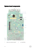
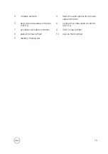
Page 14: ...System board components 1 power button cable connector 2 coin cell battery 14 ...

Page 15: ...tical drive power cable connector 5 hard drive data cable connector SATA 1 6 optical drive data cable connector SATA 2 7 processor fan cable connector 8 CMOS clear jumper 9 password clear jumper 10 service mode jumper 11 memory module slot 15 ...

Page 16: ...omputer After working inside your computer follow the instructions in After working inside your computer For more safety best practices see the Regulatory Compliance home page at www dell com regulatory_compliance Procedure 1 Place the computer on its side 2 Remove the two screws 6 32xL6 35 that secure the cover to the chassis 3 Slide the computer cover and lift it off the chassis 16 ...

Page 17: ...instructions in After working inside your computer For more safety best practices see the Regulatory Compliance home page at www dell com regulatory_compliance Procedure 1 Align the tabs on the computer cover with the slots on the chassis and slide it towards the front of the computer until it snaps into place 2 Replace the two screws 6 32xL6 35 that secure the computer cover to the chassis 3 Plac...

Page 18: ...teps in Before working inside your computer After working inside your computer follow the instructions in After working inside your computer For more safety best practices see the Regulatory Compliance home page at www dell com regulatory_compliance Prerequisites Remove the computer cover Procedure 1 Place the computer in an upright position 18 ...

Page 19: ...2 Release the tabs on the front bezel sequentially from the top by pushing them outwards from the chassis 19 ...

Page 20: ...3 Rotate and pull the front bezel away from the front of the computer to release the tabs on the front bezel from the chassis 20 ...

Page 21: ...your computer follow the instructions in After working inside your computer For more safety best practices see the Regulatory Compliance home page at www dell com regulatory_compliance Procedure 1 Align and insert the tabs on the front bezel into the slots on the chassis 2 Rotate the front bezel towards the chassis until the tabs on the front bezel snap into place Post requisites Replace the compu...

Page 22: ... your computer and follow the steps in Before working inside your computer After working inside your computer follow the instructions in After working inside your computer For more safety best practices see the Regulatory Compliance home page at www dell com regulatory_compliance Prerequisites Remove the computer cover 22 ...

Page 23: ...Place the computer with the side chassis facing up Disconnect the power cables and the data cables from the hard drive assembly 2 Remove the screw 6 32xL3 6 that secures the hard drive assembly to the drive cage 23 ...

Page 24: ...3 Slide the hard drive assembly and lift it off the drive cage 4 Remove the four screws M3xL3 5 that secure the hard drive to the hard drive bracket 24 ...

Page 25: ...5 Slide the hard drive out of the hard drive bracket NOTE Note the orientation of the hard drive so that you can replace it correctly 25 ...

Page 26: ...de the hard drive into the hard drive bracket 2 Align the screw holes on the hard drive with the screw holes on the hard drive bracket 3 Replace the four screws M3xL3 5 that secure the hard drive to the hard drive bracket 4 Slide the hard drive assembly towards the back of the slot on the drive cage until it snaps into place 5 Align the screw holes on the top hard drive with the screw holes on the...

Page 27: ...re working inside your computer After working inside your computer follow the instructions in After working inside your computer For more safety best practices see the Regulatory Compliance home page at www dell com regulatory_compliance Prerequisites Remove the computer cover Procedure 1 Disconnect the power cable and the data cable from the hard drive assembly 27 ...

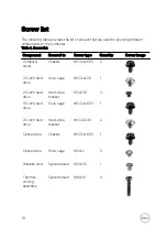
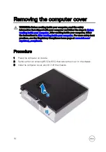
Page 28: ...2 Remove the two screws 6 32xL6 35 that secure the hard drive assembly to the drive cage 28 ...

Page 29: ...3 Slide the hard drive assembly and lift it off the drive cage 4 Turn the hard drive assembly over and remove the two screws 6 32xL3 6 that secure the hard drive bracket to the hard drive assembly 29 ...

Page 30: ...5 Slide the hard drive out of the hard drive bracket 30 ...

Page 31: ...at www dell com regulatory_compliance Procedure 1 Slide the hard drive into the hard drive bracket 2 Align the screw holes on the hard drive with the screw holes on the hard drive bracket 3 Replace the two screws 6 32xL3 6 that secure the hard drive bracket to the hard drive 4 Turn the hard drive assembly over 5 Slide the hard drive assembly into the drive cage 6 Replace the two screws 6 32xL6 35 ...

Page 32: ...nstructions in After working inside your computer For more safety best practices see the Regulatory Compliance home page at www dell com regulatory_compliance Prerequisites Remove the computer cover Procedure 1 Disconnect the data cable and power cable from the optical drive assembly 2 Disconnect the data cables and power cables from the hard drive assembly 3 Remove the two screws 6 32xL6 35 that ...

Page 33: ...4 Push the release tab on the chassis and slide the drive cage off the chassis 5 Turn the drive cage over and remove the three screws M2xL2 that secure the optical drive assembly to the drive cage 33 ...

Page 34: ...6 Slide the optical drive assembly out of the optical drive bracket 7 Gently pull and remove the optical drive bezel from the optical drive 34 ...

Page 35: ...cal drive bezel to the optical drive 2 Align the screw holes on the optical drive assembly with the screw holes on the drive cage 3 Replace the three screws M2xL2 that secure the optical drive assembly to the drive cage 4 Slide the drive cage into the slot on the chassis and snap it into place 5 Align the screw hole on the drive cage with the screw hole on the chassis 6 Replace the two screws 6 32...

Page 36: ...inside your computer After working inside your computer follow the instructions in After working inside your computer For more safety best practices see the Regulatory Compliance home page at www dell com regulatory_compliance Prerequisites 1 Remove the computer cover 2 Remove the front bezel 3 Follow the procedure from step 1 to step 4 in Removing the optical drive 36 ...

Page 37: ...Procedure 1 Locate the memory module on the system board 2 Using your fingertips carefully spread apart the securing clip at each end of the memory module slot until the memory module pops up 37 ...

Page 38: ... slot CAUTION To prevent damage to the memory module hold the memory module by the edges Do not touch the components on the memory module NOTE If the memory module is difficult to remove gently ease the memory module back and forth to remove it from the slot 38 ...

Page 39: ...e safety best practices see the Regulatory Compliance home page at www dell com regulatory_compliance Procedure 1 Align the notch on the memory module with the tab on the memory module slot 2 Slide the memory module into the memory module slot 3 Press the memory module down until it clicks into place and the securing clips are in locked position Post requisites 1 Follow the procedure from step 4 t...

Page 40: ... best practices see the Regulatory Compliance home page at www dell com regulatory_compliance CAUTION Removing the coin cell battery resets the BIOS setup program s settings to default It is recommended that you note the BIOS setup program s settings before removing the coin cell battery Prerequisites 1 Remove the computer cover 2 Remove the front bezel 3 Follow the procedure from step 1 to step 4...

Page 41: ...2 Remove the coin cell battery from the socket 41 ...

Page 42: ...he instructions in After working inside your computer For more safety best practices see the Regulatory Compliance home page at www dell com regulatory_compliance Procedure Insert a new coin cell battery CR2032 into the battery socket with the positive side facing up and snap it into place Post requisites 1 Follow the procedure from step 4 to step 8 in Replacing the optical drive 2 Replace the fro...

Page 43: ...inside your computer After working inside your computer follow the instructions in After working inside your computer For more safety best practices see the Regulatory Compliance home page at www dell com regulatory_compliance Prerequisites 1 Remove the computer cover 2 Remove the front bezel 3 Follow the procedure from step 1 to step 4 in Removing the optical drive 43 ...

Page 44: ...ss card on the system board 2 Remove the screw M2xL3 5 that secures the wireless card to the system board 3 Slide and remove the wireless card bracket from the wireless card 4 Disconnect the antenna cables from the wireless card 44 ...

Page 45: ...5 Slide and remove the wireless card from the wireless card slot 45 ...

Page 46: ...ns in After working inside your computer For more safety best practices see the Regulatory Compliance home page at www dell com regulatory_compliance Procedure 1 Connect the antenna cables to the wireless card 2 Align the screw hole on the wireless card bracket with the screw hole on the wireless card 3 Slide the wireless card at an angle into the wireless card slot 4 Replace the screw M2xL3 5 tha...

Page 47: ...Post requisites 1 Follow the procedure from step 4 to step 8 in Replacing the optical drive 2 Replace the front bezel 3 Replace the computer cover 47 ...

Page 48: ...your computer For more safety best practices see the Regulatory Compliance home page at www dell com regulatory_compliance Prerequisites 1 Remove the computer cover 2 Remove the front bezel 3 Follow the procedure from step 1 to step 4 in Removing the optical drive 4 Remove the wireless card Procedure 1 Note the antenna cable routing and remove the antenna cables from the routing guide on the chass...

Page 49: ...3 Remove the antenna modules along with the cables off the chassis 49 ...

Page 50: ...n After working inside your computer For more safety best practices see the Regulatory Compliance home page at www dell com regulatory_compliance Procedure 1 Align and adhere the antenna modules to the chassis 2 Route the antenna cables through the routing guides on the chassis Post requisites 1 Replace the wireless card 2 Follow the procedure from step 4 to step 8 in Replacing the optical drive 3...

Page 51: ...your computer follow the instructions in After working inside your computer For more safety best practices see the Regulatory Compliance home page at www dell com regulatory_compliance Prerequisites 1 Remove the computer cover 2 Remove the front bezel 3 Follow the procedure from step 1 to step 4 in Removing the optical drive Procedure 1 Remove the screw 6 32xL6 35 that secures the front I O bracke...

Page 52: ...Do not extend the front I O bracket too far to prevent damage to the antennas 3 Disconnect the power button cable from the system board 4 Press the tab on the top of the power button module and push the power button module to release it from the front panel 52 ...

Page 53: ...5 Remove the power button module along with its cable through the slot on the front panel 53 ...

Page 54: ...Route the power button board cable through the slot on the front panel 2 Align and snap the power button module into the slot on the front panel 3 Connect the power button board cable to the system board 4 Rotate the front I O bracket towards the chassis 5 Align the screw hole on the front I O bracket with the screw hole on the chassis 6 Replace the screw 6 32xL6 35 that secures the front I O brac...

Page 55: ...er working inside your computer follow the instructions in After working inside your computer For more safety best practices see the Regulatory Compliance home page at www dell com regulatory_compliance Prerequisites Remove the computer cover Procedure 1 Disconnect the processor fan cable from the system board 2 Remove the four screws M6xL10 that secure the thermal cooling assembly to the system b...

Page 56: ...3 Lift the thermal cooling assembly off the system board 56 ...

Page 57: ...uctions in After working inside your computer For more safety best practices see the Regulatory Compliance home page at www dell com regulatory_compliance Procedure 1 Align the screw holes on the thermal cooling assembly with the screw holes on the system board 2 Replace the four screws M6xL10 that secure the thermal cooling assembly to the system board 3 Connect the processor fan cable to the sys...

Page 58: ... the BIOS using the BIOS setup program You must make the appropriate changes again after you replace the system board NOTE Before disconnecting the cables from the system board note the location of the connectors so that you can reconnect the cables correctly after you replace the system board Prerequisites 1 Remove the computer cover 2 Remove the front bezel 3 Follow the procedure from step 1 to ...

Page 59: ...ont I O bracket too far to prevent damage to the antennas 3 Disconnect the optical drive data cable SATA 2 from the system board 4 Disconnect the hard drive data cable SATA 1 from the system board 5 Disconnect the hard drive and optical drive power cable from the system board 59 ...

Page 60: ...6 Disconnect the power button cable from the system board 7 Remove the six screws 6 32xL6 35 that secure the system board to the chassis 60 ...

Page 61: ...8 Slide and lift the system board off the chassis 61 ...

Page 62: ...e BIOS using the BIOS setup program You must make the appropriate changes again after you replace the system board Procedure 1 Align the system board with the slots on the chassis and place the system board in position 2 Replace the six screws 6 32xL6 35 that secure the system board to the chassis 3 Connect the optical drive data cable hard drive data cable hard drive and optical drive power cable...

Page 63: ...3 Replace the memory module 4 Follow the procedure from step 5 to step 8 in Replacing the optical drive 5 Replace the front bezel 6 Replace the computer cover 63 ...

Page 64: ... My System 9 Click Download and Install to download and install all driver updates detected for your computer 10 Select a location to save the files 11 If prompted approve requests from User Account Control to make changes on the system 12 The application installs all drivers and updates identified NOTE Not all files can be installed automatically Review the installation summary to identify if man...

Page 65: ...nd install all driver updates detected for your computer 10 Select a location to save the files 11 If prompted approve requests from User Account Control to make changes on the system 12 The application installs all drivers and updates identified NOTE Not all files can be installed automatically Review the installation summary to identify if manual installation is necessary 13 For manual download ...

Page 66: ...User Account Control to make changes on the system 12 The application installs all drivers and updates identified NOTE Not all files can be installed automatically Review the installation summary to identify if manual installation is necessary 13 For manual download and installation click Category 14 Click Chipset in the drop down list 15 Click Download to download the USB driver for your computer...

Page 67: ...stallation summary to identify if manual installation is necessary 13 For manual download and installation click Category 14 Click Chipset in the drop down list 15 Click Download to download the appropriate chipset driver for your computer 16 After the download is complete navigate to the folder where you saved the chipset driver file 17 Double click the chipset driver file icon and follow the ins...

Page 68: ...ake changes on the system 12 The application installs all drivers and updates identified NOTE Not all files can be installed automatically Review the installation summary to identify if manual installation is necessary 13 For manual download and installation click Category 14 Click Network in the drop down list 15 Click Download to download the network driver for your computer 16 Save the file and...

Page 69: ...up the one time boot menu by pressing F12 key The one time boot menu displays the devices that you can boot from including the diagnostic option The boot menu options are Removable Drive if available STXXXX Drive NOTE XXX denotes the SATA drive number Optical Drive if available SATA Hard Drive if available Diagnostics NOTE Choosing Diagnostics will display the ePSA diagnostics screen The boot sequ...

Page 70: ...CAUTION Unless you are an expert computer user do not change the settings in the BIOS Setup program Certain changes can make your computer work incorrectly NOTE Before you change BIOS Setup program it is recommended that you write down the BIOS Setup program screen information for future reference Use the BIOS Setup program for the following purposes Get information about the hardware installed in...

Page 71: ...led devices the items listed in this section may or may not appear Table 2 System setup options Main menu Main System Time Displays the current time in hh mm ss format System Date Displays the current date in mm dd yyyy format BIOS Version Displays the BIOS version number Product Name Displays the product name Service Tag Enables you to enter the service tag of your computer Asset Tag Displays the...

Page 72: ...isable Intel Virtualization Technology feature for the processor VT for Direct I O Enables you to enable or disable Intel Virtualization Technology feature for the Direct I O Integrated NIC Enables you to enable or disable the on board LAN controller Default Enabled SATA Operation Enables you to configure the operating mode of the integrated SATA hard drive controller Default AHCI Adapter Warnings...

Page 73: ...able the front USB ports Rear USB Ports Enables you to enable or disable the rear USB ports Power Options Wake Up by Integrated LAN Enables the computer to be powered on by special LAN signals AC Recovery Sets what action the computer takes when power is restored Deep Sleep Control Enables you to define the controls when Deep Sleep is enabled USB Wake Support Enables you to enable the USB devices ...

Page 74: ...tatus Displays whether the admin password is set System Password Status Displays whether the system password is set HDD Password Status Displays if the hard drive password is set Admin Password Enables you to set the admin password System Password Enables you to set the system password HDD Password Enables you to set the hard drive password Password Change Enable or disable changes to the System a...

Page 75: ...Firmware Capsule Updates function Default Enabled Table 5 System setup options Boot menu Boot Boot List Option Displays the available boot devices File Browser Add Boot Option Enables you to set the boot path in the boot option list File Browser Del Boot Option Enables you to delete the boot path in the boot option list Secure Boot Enables you to enable or disable the secure boot control Default D...

Page 76: ...u replace the system board Follow these steps to flash the BIOS 1 Turn on your computer 2 Go to www dell com support 3 Click Product support enter the Service Tag of your computer and then click Submit NOTE If you do not have the Service Tag use the auto detect feature or manually browse for your computer model 4 Click Drivers downloads Find it myself 5 Select the operating system installed on you...

Page 77: ...7 Click Download to download the latest version of the BIOS for your computer 8 After the download is complete navigate to the folder where you saved the BIOS update file 9 Double click the BIOS update file icon and follow the instructions on the screen Reinstall Windows using a USB recovery drive CAUTION This process formats the hard drive and removes all data on your computer Ensure that you bac...

Page 78: ...r computers may cause invalid results or error messages The ePSA diagnostics also known as system diagnostics performs a complete check of your hardware The ePSA is embedded with the BIOS and is launched by the BIOS internally The embedded system diagnostics provides a set of options for particular devices or device groups allowing you to Run tests automatically or in an interactive mode Repeat te...

Page 79: ...on number and contact Dell Diagnostics The computer POST Power On Self Test ensures that it meets the basic computer requirements and the hardware is working appropriately before the boot process begins If the computer passes the POST the computer continues to start in a normal mode However if the computer fails the POST the computer emits a series of LED codes during the start up The system LED i...

Page 80: ...om your computer 3 Press and hold the power button for 15 seconds to drain the flea power 4 Connect the power adapter to your computer 5 Turn on your computer Wi Fi power cycle If your computer is unable to access the internet due to Wi Fi connectivity issues a Wi Fi power cycle procedure may be performed The following procedure provides the instructions on how to conduct a Wi Fi power cycle NOTE ...

Page 81: ...tem www dell com support windows www dell com support linux Troubleshooting information user manuals setup instructions product specifications technical help blogs drivers software updates and so on www dell com support Dell knowledge base articles for a variety of computer concerns 1 Go to www dell com support 2 Type the subject or keyword in the Search box 3 Click Search to retrieve the related ...

Page 82: ...h the drop down menu under View Products Enter the Service Tag number or Product ID in the search bar Contacting Dell To contact Dell for sales technical support or customer service issues see www dell com contactdell NOTE Availability varies by country and product and some services may not be available in your country NOTE If you do not have an active internet connection you can find contact info...

Reviews: