background image

Dell™ OptiPlex™ GX520 User's Guide


Mini Tower Computer


Desktop Computer


Small Form Factor Computer


Summary of Contents for OptiPlex GX520

Page 1: ...Dell OptiPlex GX520 User s Guide Mini Tower Computer Desktop Computer Small Form Factor Computer ...

Page 2: ...h are available on the Dell Support website at support dell com Dell OpenManage IT Assistant IT Assistant configures manages and monitors computers and other devices on a corporate network IT Assistant manages assets configurations events alerts and security for computers equipped with industry standard management software It supports instrumentation that conforms to SNMP DMI and CIM industry stan...

Page 3: ...hassis Intrusion option press the left or right arrow key to select Reset and then choose On On Silent or Off l On Silent default setting If the computer cover is opened the setting changes to Detected No alert message appears during the boot sequence at the next computer start up l Off No intrusion monitoring occurs and no messages appear Padlock Ring and Security Cable Slot Use one of the follow...

Page 4: ...new system password is less than 32 characters the whole field fills with placeholders Then the option heading changes to Verify Password followed by another empty 32 character field in square brackets 5 To confirm your password type it a second time and press Enter The password setting changes to Set 6 Exit system setup Password protection takes effect when you restart the computer Typing Your Sy...

Page 5: ...verify that Admin Password is set to Not Set 2 Highlight Admin Password and press the left or right arrow key The computer prompts you to type and verify the password If a character is not permitted the computer emits a beep 3 Type and then verify the password After you verify the password the Admin Password setting changes to Set The next time you enter system setup the computer prompts you for t...

Page 6: ...ing System Setup 1 Turn on or restart your computer 2 When the blue DELL logo appears press F2 immediately If you wait too long and the operating system logo appears continue to wait until you see the Microsoft Windows desktop Then shut down your computer and try again System Setup Screens The system setup screen displays current or changeable configuration information for your computer Informatio...

Page 7: ...exibility Combination The hard drive controller is configured for combination mode This mode enables compatibility with some older operating systems that do not support SATA drives The factory default setting is Normal NOTE Changing this setting affects the order in which drives are listed However system setup does not reflect these changes until after a reboot SATA Reporting Controls whether hard...

Page 8: ...ormance mode may cause the drive to be noisier but its performance is not affected Changing the acoustics setting does not alter your hard drive image Security This section displays available system security options See Security for more information Admin Password This option provides restricted access to the computer s System Setup program in the same way that access to the system can be restrict...

Page 9: ... work if you turn off your computer using a power strip or surge protector Auto Power Time Sets the specific time to automatically turn on the computer Time is kept in a 24 hour format hours minutes Change the start up time by pressing the right or left arrow key to increase or decrease the numbers or type numbers in both the date and time fields Use this setting in conjunction with the Auto Power...

Page 10: ...tup 2 Use the arrow keys to highlight the Boot Sequence menu option and press Enter to access the pop up menu 3 Press the up and down arrow keys to move through the list of devices 4 Press the spacebar to enable or disable a device Enabled devices have a checkmark 5 Press Shift Up Arrow or Shift Down Arrow to move a selected device up or down the list Booting to a USB Device Memory Key 1 Insert th...

Page 11: ...begin any of the procedures in this section follow the safety instructions located in the Product Information Guide NOTICE This process erases both the system and administrator passwords Mini Tower Computer Desktop Computer Small Form Computer Jumper Setting Description PSWD Password features are enabled default setting Password features are disabled RTCRST The real time clock has not been reset ...

Page 12: ...yper Threading Hyper Threading is an Intel technology that can enhance overall computer performance by allowing one physical processor to function as two logical processors capable of performing certain tasks simultaneously It is recommended that you use the Microsoft Windows XP Service Pack 1 SP1 or higher operating system because Windows XP is optimized to take advantage of Hyper Threading techn...

Page 13: ...mode l Shutdown This sleep mode removes all power from the computer except a small auxiliary amount As long as the computer remains connected to an electrical outlet it can be automatically or remotely started For example the Auto Power On option in system setup allows the computer to automatically start at a specified time Also your network administrator can remotely start your computer using a p...

Page 14: ...p 2 Follow the procedures in Before You Begin 3 Locate the battery socket 4 Remove the system battery a Support the battery connector by pressing down firmly on the positive side of the connector b While supporting the battery connector press the battery tab away from the positive side of the connector and pry the battery it up out of the securing tabs at the negative side of the connector CAUTION...

Page 15: ...aight down into the connector until it snaps into place 2 Replace the computer cover 3 Enter system setup and restore the settings you recorded in step 1 4 Properly dispose of the old battery as described in the Product Information Guide Back to Contents Page 1 system battery 2 positive side of battery connector 3 battery socket tab 4 battery socket NOTICE To avoid damage to the battery connector ...

Page 16: ...to help ensure your own personal safety To avoid damaging the computer perform the following steps before you begin working inside the computer 1 Turn off your computer 2 Disconnect any telephone or telecommunication lines from the computer 3 Disconnect your computer and all attached devices from their electrical outlets and then press the power button to ground the system board NOTICE To avoid lo...

Page 17: ...l form factor computer cover Back to Contents Page CAUTION To guard against electrical shock always unplug your computer from the electrical outlet before removing the cover NOTICE Before touching anything inside your computer ground yourself by touching an unpainted metal surface such as the metal at the back of the computer While you work periodically touch an unpainted metal surface to dissipat...

Page 18: ... avoid damaging the computer perform the following steps before you begin working inside the computer 1 Turn off your computer 2 Disconnect any telephone or telecommunication lines from the computer NOTICE To avoid losing data save and close any open files and exit any open programs before you turn off your computer CAUTION Before you begin any of the procedures in this section follow the safety i...

Page 19: ...r computer cover l Remove the desktop computer cover l Remove the small form factor computer cover Back to Contents Page CAUTION To guard against electrical shock always unplug your computer from the electrical outlet before removing the cover NOTICE Before touching anything inside your computer ground yourself by touching an unpainted metal surface such as the metal at the back of the computer Wh...

Page 20: ...d Note the routing of the chassis intrusion cable as you remove it from the chassis Chassis hooks may hold the cable in place inside the chassis 3 Using a flat blade screwdriver gently slide the chassis intrusion switch out of its slot and remove the switch and its attached cable from the computer Mini Tower Computer Desktop Computer CAUTION Before you begin any of the procedures in this section f...

Page 21: ...ssis Intrusion Detector 1 Turn on or restart your computer 2 When the blue DELL logo appears press F2 immediately If you wait too long and the operating system logo appears continue to wait until you see the Microsoft Windows desktop Then shut down your computer and try again 3 Select the Chassis Intrusion option and then press the left or right arrow key to select Reset Change the setting to On O...

Page 22: ...4 Press Alt b to restart the computer and implement your changes Back to Contents Page ...

Page 23: ...ive Clean your floppy drive using a commercially available cleaning kit These kits contain pretreated floppy disks to remove contaminants that accumulate during normal operation CDs and DVDs If you notice problems such as skipping with the playback quality of your CDs or DVDs try cleaning the discs 1 Hold the disc by its outer edge You can also touch the inside edge of the center hole 2 With a sof...

Page 24: ...some protection from dust fingerprints and scratches Cleaning products for CDs are safe to use on DVDs Back to Contents Page ...

Page 25: ...ch the computer stand if applicable For instructions see the documentation that came with the stand 5 Connect your computer and devices to electrical outlets and turn them on After you remove and replace the cover the chassis intrusion detector if installed and enabled causes the following message to appear on the screen at the next computer start up ALERT Cover was previously removed 6 Reset the ...

Page 26: ...ection Agency As an ENERGY STAR partner Dell Inc has determined that this product meets the ENERGY STAR guidelines for energy efficiency Other trademarks and trade names may be used in this document to refer to either the entities claiming the marks and names or their products Dell Inc disclaims any proprietary interest in trademarks and trade names other than its own Model DCNE October 2006 P N W...

Page 27: ...erence material for technicians or experienced users NOTE Drivers and documentation updates can be found at support dell com NOTE The Drivers and Utilities CD is optional and may not ship with your computer l How to set up my computer l Basic troubleshooting information l How to run the Dell Diagnostics l Error codes and diagnostic lights l Tools and utilities l How to remove and install parts Qui...

Page 28: ... updates for your operating system and support for Dell 3 5 inch USB floppy drives Intel Pentium M processors optical drives and USB devices DSS is necessary for correct operation of your Dell computer The software automatically detects your computer and operating system and installs the updates appropriate for your configuration Dell Support Website support dell com NOTE Select your region to vie...

Page 29: ......

Page 30: ...ort personnel If you do not have an Express Service Code open the Dell Accessories folder double click the Express Service Code icon and follow the directions For instructions on using the technical support service see Technical Support Service NOTE Some of the following services are not always available in all locations outside the continental U S Call your local Dell representative for informati...

Page 31: ...rdware Our technical support staff uses computer based diagnostics to provide fast accurate answers To contact Dell s technical support service see Technical Assistance and then call the number for your country as listed in Contacting Dell Problems With Your Order If you have a problem with your order such as missing parts wrong parts or incorrect billing contact Dell for customer assistance Have ...

Page 32: ...computers is available at a separate telephone number listed for participating countries If you do not see a telephone number listed that is specific for Inspiron XPS computers you may contact Dell through the technical support number listed and your call will be routed appropriately When you need to contact Dell use the electronic addresses telephone numbers and codes provided in the following ta...

Page 33: ...nts Corporate Customer Care 0820 240 530 16 Home Small Business Technical Support 0820 240 530 14 Preferred Accounts Corporate Technical Support 0660 8779 Switchboard 0820 240 530 00 Bahamas General Support toll free 1 866 278 6818 Barbados General Support 1 800 534 3066 Belgium Brussels International Access Code 00 Country Code 32 City Code 2 Website support euro dell com E mail for French speaki...

Page 34: ...e 800 858 2628 Large Corporate Accounts North toll free 800 858 2999 Large Corporate Accounts North Government and Education toll free 800 858 2955 Large Corporate Accounts East toll free 800 858 2020 Large Corporate Accounts East Government and Education toll free 800 858 2669 Large Corporate Accounts Queue Team toll free 800 858 2572 Large Corporate Accounts South toll free 800 858 2355 Large Co...

Page 35: ...Care 0180 5 224400 Global Segment Customer Care 06103 766 9570 Preferred Accounts Customer Care 06103 766 9420 Large Accounts Customer Care 06103 766 9560 Public Accounts Customer Care 06103 766 9555 Switchboard 06103 766 7000 Greece International Access Code 00 Country Code 30 Website support euro dell com E mail support euro dell com gr en emaildell Technical Support 00800 44 14 95 18 Gold Servi...

Page 36: ...e 0120 198 226 Technical Support outside of Japan Dimension and Inspiron 81 44 520 1435 Technical Support Dell Precision OptiPlex and Latitude toll free 0120 198 433 Technical Support outside of Japan Dell Precision OptiPlex and Latitude 81 44 556 3894 Technical Support PDAs projectors printers routers toll free 0120 981 690 Technical Support outside of Japan PDAs projectors printers routers 81 44...

Page 37: ...822 Netherlands Antilles General Support 001 800 882 1519 Netherlands Amsterdam International Access Code 00 Country Code 31 City Code 20 Website support euro dell com Technical Support for Inspiron XPS computers only 020 674 45 94 Technical Support for all other Dell computers 020 674 45 00 Technical Support Fax 020 674 47 66 Home Small Business Customer Care 020 674 42 00 Relational Customer Car...

Page 38: ...49 Transaction Sales toll free 1 800 394 7412 Corporate Sales toll free 1 800 394 7419 Slovakia Prague International Access Code 00 Country Code 421 Website support euro dell com E mail czech_dell dell com Technical Support 02 5441 5727 Customer Care 420 22537 2707 Fax 02 5441 8328 Tech Fax 02 5441 8328 Switchboard Sales 02 5441 7585 South Africa Johannesburg International Access Code 09 091 Count...

Page 39: ...06 Trinidad Tobago General Support 1 800 805 8035 Turks and Caicos Islands General Support toll free 1 866 540 3355 U K Bracknell International Access Code 00 Country Code 44 City Code 1344 Website support euro dell com Customer Care website support euro dell com uk en ECare Form Home asp E mail dell_direct_support dell com Technical Support Corporate Preferred Accounts PAD 1000 employees 0870 908...

Page 40: ...tomers toll free 1 800 234 1490 Dell Sales toll free 1 800 289 3355 or toll free 1 800 879 3355 Dell Outlet Store Dell refurbished computers toll free 1 888 798 7561 Software and Peripherals Sales toll free 1 800 671 3355 Spare Parts Sales toll free 1 800 357 3355 Extended Service and Warranty Sales toll free 1 800 247 4618 Fax toll free 1 800 727 8320 Dell Services for the Deaf Hard of Hearing or...

Page 41: ...nt console ASF is designed to be platform and operating system independent B backup A copy of a program or data file on a floppy disk CD or hard drive As a precaution back up the data files from your hard drive regularly battery An internal power source used to operate portable computers when not connected to an AC adapter and an electrical outlet battery life span The length of time years during ...

Page 42: ...s a merchandise passport CD compact disc An optical form of storage media typically used for audio and software programs CD drive A drive that uses optical technology to read data from CDs CD player The software used to play music CDs The CD player displays a window with buttons that you use to play a CD CD R CD recordable A recordable version of a CD Data can be recorded only once onto a CD R Onc...

Page 43: ... generally allow the user to select the data unit size or stripe width DMA direct memory access A channel that allows certain types of data transfer between RAM and a device to bypass the processor docking device See APR DMTF Distributed Management Task Force A consortium of hardware and software companies who develop management standards for distributed desktop network enterprise and Internet env...

Page 44: ...I electromagnetic interference Electrical interference caused by electromagnetic radiation ENERGY STAR Environmental Protection Agency requirements that decrease the overall consumption of electricity EPP enhanced parallel port A parallel connector design that provides bidirectional data transmission ESD electrostatic discharge A rapid discharge of static electricity ESD can damage integrated circ...

Page 45: ...d interfaces are often measured in GHz graphics mode A video mode that can be defined as x horizontal pixels by y vertical pixels by z colors Graphics modes can display an unlimited variety of shapes and fonts GUI graphical user interface Software that interacts with the user by means of menus windows and icons Most programs that operate on the Windows operating systems are GUIs H hard drive A dri...

Page 46: ...connector or expansion slot and allows the processor to communicate with that device IrDA Infrared Data Association The organization that creates international standards for infrared communications IRQ interrupt request An electronic pathway assigned to a specific device so that the device can communicate with the processor Each device connection must be assigned an IRQ Although two devices can sh...

Page 47: ...n contain several different forms of memory such as RAM ROM and video memory Frequently the word memory is used as a synonym for RAM memory address A specific location where data is temporarily stored in RAM memory mapping The process by which the computer assigns memory addresses to physical locations at start up Devices and software can then identify information that the processor can access mem...

Page 48: ...h partition can contain multiple logical drives PC Card A removable I O card adhering to the PCMCIA standard Modems and network adapters are common types of PC Cards PCI peripheral component interconnect PCI is a local bus that supports 32 and 64 bit data paths providing a high speed data path between the processor and devices such as video drives and networks PCMCIA Personal Computer Memory Card ...

Page 49: ... and the system administrator has assigned rights only to specific individuals refresh rate The frequency measured in Hz at which your screen s horizontal lines are recharged sometimes also referred to as its vertical frequency The higher the refresh rate the less video flicker can be seen by the human eye resolution The sharpness and clarity of an image produced by a printer or displayed on a mon...

Page 50: ... audio from one file to another without converting it to and from an analog format which could degrade the quality of the file standby mode A power management mode that shuts down all unnecessary computer operations to save energy surge protectors Prevent voltage spikes such as those that may occur during an electrical storm from entering the computer through the electrical outlet Surge protectors...

Page 51: ...o protect against interference UXGA ultra extended graphics array A video standard for video cards and controllers that supports resolutions up to 1600 x 1200 V video controller The circuitry on a video card or on the system board in computers with an integrated video controller that provides the video capabilities in combination with the monitor for your computer video memory Memory that consists...

Page 52: ... the open position X XGA extended graphics array A video standard for video cards and controllers that supports resolutions up to 1024 x 768 Z ZIF zero insertion force A type of socket or connector that allows a computer chip to be installed or removed with no stress applied to either the chip or its socket Zip A popular data compression format Files that have been compressed with the Zip format a...

Page 53: ...ms such as Microsoft Windows XP can only use a maximum of 4 GB of address space however the amount of memory available to the operating system is less than 4 GB Certain components within the computer require address space in the 4 GB range Any address space reserved for these components cannot be used by computer memory The following components require memory address space l System ROM l APIC s l ...

Page 54: ...properly You should install your original memory modules in pairs either in connectors DIMM1 and DIMM2 or connectors DIMM3 and DIMM4 NOTICE Removing memory modules from DIMM2 and DIMM4 on the desktop computer requires you to remove the optical drive see Drives Failure to do so may cause damage to the memory module and the DIMM socket NOTE Memory purchased from Dell is covered under your computer w...

Page 55: ...y The computer should have changed the value of System Memory to reflect the newly installed memory Verify the new total If it is correct skip to step 9 8 If the memory total is incorrect turn off and disconnect your computer and devices from their electrical outlets Open the computer cover and check the installed memory modules to ensure that they are seated properly in their sockets Then repeat ...

Page 56: ...upports a maximum of 4 GB of memory when you use two 2 GB DIMMs Current operating systems such as Microsoft Windows XP can only use a maximum of 4 GB of address space however the amount of memory available to the operating system is less than 4 GB Certain components within the computer require address space in the 4 GB range Any address space reserved for these components cannot be used by compute...

Page 57: ...from Dell If possible do not pair an original memory module with a new memory module Otherwise your computer may not start properly You should install your original memory modules in pairs either in connectors DIMM1 and DIMM2 or connectors DIMM3 and DIMM4 NOTICE Removing memory modules from DIMM2 and DIMM4 on the desktop computer requires you to remove the optical drive see Drives Failure to do so...

Page 58: ...he value of System Memory to reflect the newly installed memory Verify the new total If it is correct skip to step 9 8 If the memory total is incorrect turn off and disconnect your computer and devices from their electrical outlets Open the computer cover and check the installed memory modules to ensure that they are seated properly in their sockets Then repeat steps 5 6 and 7 9 When the System Me...

Page 59: ...s established 5 diagnostic lights Use the lights to help you troubleshoot a computer problem based on the diagnostic code For more information see Diagnostic Lights 6 power button Press this button to turn on the computer NOTICE To avoid losing data do not turn off the computer by pressing the power button for 6 seconds or longer Instead perform an operating system shutdown NOTICE If your operatin...

Page 60: ...ock ring Insert a padlock to lock the computer cover 3 voltage selection switch Your computer is equipped with a manual voltage selection switch To help avoid damaging a computer with a manual voltage selection switch set the switch for the voltage that most closely matches the AC power available in your location Also ensure that your monitor and attached devices are electrically rated to operate ...

Page 61: ...o ensure reliable operation 4 network activity light This light flashes yellow when the computer is transmitting or receiving network data A high volume of network traffic may make this light appear to be in a steady on state 5 line in connector Use the blue line in connector to attach a record playback device such as a cassette player CD player or VCR On computers with a sound card use the connec...

Page 62: ...l outlet before removing the computer cover NOTICE Be careful when opening the computer cover to ensure that you do not accidentally disconnect cables from the system board 1 CD DVD drive 5 system board 2 floppy drive 6 heat sink assembly 3 power supply 7 hard drive 4 chassis manual voltage selection switch 1 fan connector FAN 12 password jumper PSWD 2 processor connector CPU 13 battery socket BAT...

Page 63: ...8 floppy drive connector DSKT 8 power connector POWER 19 standby power indicator AUX_PWR 9 CD DVD drive connector IDE 20 system board speaker BEEP 10 RTC reset jumper RTCRST 21 internal speaker INT_SPKR 11 chassis manual voltage selection switch connector INTRUDER Mini Tower Computer Jumper Setting Description PSWD Password features are enabled default Password features are disabled RTCRST The rea...

Page 64: ...tention mechanism and grip the bottom of the retention mechanism with your fingers b With your free hand gently squeeze the sides of the card retention mechanism to release it from the tab slots holding it in place c Pivot the card retention mechanism upward to release it from the two tab slots CAUTION Before you begin any of the procedures in this section follow the safety instructions located in...

Page 65: ...d card s connectors Do not connect external audio devices to the microphone speaker headphone or line in connectors on the back panel of the computer 15 If you installed an network adapter card and want to turn off the integrated network adapter NOTE See the documentation that came with the card for information on configuring the card making internal connections or customizing it for your computer...

Page 66: ...ntly squeeze the sides of the card retention mechanism to release it from the tab slots holding it in place c Pivot the card retention mechanism upward to release it from the two tab slots 4 If necessary disconnect any cables connected to the card 5 Grasp the card by its top corners and ease it out of its connector 6 If you are removing the card permanently install a filler bracket in the empty ca...

Page 67: ...e the setting to On b Connect the network cable to the integrated network connector on the back panel of the computer PCI Express Cards Your computer supports one PCI Express x1 card If you are installing or replacing a PCI Express card follow the procedures in the next section If you are removing but not replacing a card see Removing a PCI Express Card If you are replacing a card uninstall the dr...

Page 68: ...to the card If your card includes a card retention bar remove the bar Gently pull the securing tab grasp the card by its top corners and ease it out of its connector 6 Prepare the new card for installation See the documentation that came with the card for information on configuring the card making internal connections or otherwise customizing it for your computer 7 If you are installing the card i...

Page 69: ...ices to the microphone speaker headphone or line in connectors on the back panel of the computer 15 If you installed an network adapter card and want to turn off the integrated network adapter a Enter system setup select Network Controller and change the setting to Off b Connect the network cable to the network adapter card s connectors Do not connect the network cable to the integrated network co...

Page 70: ...y press down on the card retention mechanism to secure the adapter bracket in place 7 Secure the card s by closing the card retention latch and snapping it into place 8 Replace the computer cover Serial Port Adapters Installing a Serial Port Adapter 1 Follow the procedures in Before You Begin 1 card retention latch 4 card edge connector 2 alignment guide 5 card connector 3 card 6 release tab NOTE ...

Page 71: ...rial port adapter bracket in the connector and press down firmly Ensure that the adapter is fully seated in the slot 5 Before you replace and lower the card retention mechanism ensure that l The tops of all adapters and filler brackets are flush with the alignment bar l The notch in the top of the adapter or filler bracket fits around the alignment guide 6 Gently press down on the card retention m...

Page 72: ... the retention lever 3 If necessary disconnect any cables connected to the adapter 4 Grasp the serial port adapter bracket by its top corners and ease it out of its connector 5 Replace the computer cover Back to Contents Page NOTICE Do not route cables over or behind any installed cards Cables routed over the cards can prevent the computer cover from closing properly or cause damage to the equipme...

Page 73: ...ivot the cover up using the hinge tabs as leverage points 5 Remove the cover from the hinge tabs and set it aside on a soft nonabrasive surface Back to Contents Page CAUTION Before you begin any of the procedures in this section follow the safety instructions located in the Product Information Guide CAUTION To guard against electrical shock always unplug your computer from the electrical outlet be...

Page 74: ...e device attached to the last connector on the interface cable is the master or boot device drive 0 and the device attached to the middle connector on the interface cable is the slave device drive 1 See the drive documentation in your upgrade kit for information on configuring devices for the cable select setting Connecting Drive Cables When you install a drive you connect two cables a DC power ca...

Page 75: ...he connector detaches When connecting and disconnecting a serial ATA data cable hold the cable by the black connector at each end Like IDE connectors the serial ATA interface connectors are keyed for correct insertion that is a notch or a missing pin on one connector matches a tab or a filled in hole on the other connector Hard Drive 1 colored stripe on IDE cable 2 interface cable connector 3 inte...

Page 76: ...ard 5 Press in on the blue release tabs on each side of the drive and slide the drive up and out of the computer Installing a Hard Drive 1 Unpack the replacement hard drive and prepare it for installation CAUTION To guard against electrical shock always unplug your computer from the electrical outlet before removing the computer cover NOTICE To avoid damage to the drive do not set it on a hard sur...

Page 77: ...ard drive cables to the drive Connect the hard drive cable to the connector on the system board 6 Check all connectors to be certain that they are properly cabled and firmly seated 7 Replace the computer cover NOTE If your replacement hard drive does not have the plastic hard drive bracket attached remove the bracket from the existing drive by unsnapping it from the drive Snap the bracket onto the...

Page 78: ... out of the bay 4 Gently spread the sides of the drive bracket and slide the hard drive into the bracket until the drive clicks into place 5 Move the first hard drive from the upper bay to the lower bay a Disconnect the power and the hard drive cables from the back of the first hard drive b Press in on the blue release tabs on each side of the drive and slide the first hard drive up and out of the...

Page 79: ...ard drive 10 Replace the computer cover Drive Panel Inserts If you are installing a new floppy or CD DVD drive instead of replacing a drive remove the drive panel inserts 1 Follow the procedures in Before You Begin 2 Remove the drive panel by sliding the drive release latch downward to open the panel Then remove it from the hinges 1 hard drive cable 2 hard drive cable on system board 3 power cable...

Page 80: ...ess the release tab of the insert to remove it from the drive panel 5 Reattach the drive panel to the front of the computer The drive panel only fits one way 1 drive panel 2 release tab 3 drive panel insert 1 CD DVD drive panel insert 2 floppy drive panel insert 3 holder for shoulder screws ...

Page 81: ... existing drive and attach the screws to the replacement drive 2 If you are installing a new floppy drive remove the drive panel insert for your new drive remove the shoulder screws from the inside of the drive panel insert and attach the screws to the new drive 3 Align the shoulder screws on the floppy drive with the shoulder screw slots and gently slide the drive into the bay until it clicks int...

Page 82: ...VD Drive Removing a CD DVD Drive 1 Follow the procedures in Before You Begin 1 floppy drive 2 shoulder screws 4 3 shoulder screw slots 2 1 power cable 2 floppy drive cable 3 floppy drive connector DSKT CAUTION Before you begin any of the procedures in this section follow the safety instructions located in the Product Information Guide CAUTION To guard against electrical shock always unplug your co...

Page 83: ... are installing a new CD DVD drive remove the drive panel insert for your new drive remove the shoulder screws from the inside of the drive panel insert and attach the screws to the new drive 4 Check the documentation that accompanied the drive to verify that the drive is configured for your computer If you are installing an IDE drive configure the drive for the cable select setting by using the d...

Page 84: ...system setup by setting the appropriate Drive option 0 or 1 under Drives 10 Verify that your computer works correctly by running the Dell Diagnostics Back to Contents Page 1 CD DVD drive 2 shoulder screws 3 3 shoulder screw slots 2 NOTE The CD DVD drive cable may be a SATA cable and appear differently than the image below For information on SATA cable connectors see General Installation Guidelines...

Page 85: ...e device attached to the last connector on the interface cable is the master or boot device drive 0 and the device attached to the middle connector on the interface cable is the slave device drive 1 See the drive documentation in your upgrade kit for information on configuring devices for the cable select setting Connecting Drive Cables When you install a drive you connect two cables a DC power ca...

Page 86: ...he connector detaches When connecting and disconnecting a serial ATA data cable hold the cable by the black connector at each end Like IDE connectors the serial ATA interface connectors are keyed for correct insertion that is a notch or a missing pin on one connector matches a tab or a filled in hole on the other connector Hard Drive 1 colored stripe on IDE cable 2 interface cable connector 3 inte...

Page 87: ...ard drive cable from the system board 5 Press in on the blue release tabs on each side of the drive and slide the drive up and out of the computer Installing a Hard Drive CAUTION To guard against electrical shock always unplug your computer from the electrical outlet before removing the computer cover NOTICE To avoid damage to the drive do not set it on a hard surface Instead set the drive on a su...

Page 88: ...l it clicks into place 5 Connect the power and hard drive cables to the drive Connect the hard drive cable to the connector on the system board 6 Check all connectors to be certain that they are properly cabled and firmly seated NOTE If your replacement hard drive does not have the plastic hard drive bracket attached remove the bracket from the existing drive by unsnapping it from the drive Snap t...

Page 89: ...bracket up and out of the bay 4 Gently spread the sides of the drive bracket and slide the hard drive into the bracket until the drive clicks into place 5 Move the first hard drive from the upper bay to the lower bay a Disconnect the power and the hard drive cables from the back of the first hard drive b Press in on the blue release tabs on each side of the drive and slide the first hard drive up ...

Page 90: ...ard drive 10 Replace the computer cover Drive Panel Inserts If you are installing a new floppy or CD DVD drive instead of replacing a drive remove the drive panel inserts 1 Follow the procedures in Before You Begin 2 Remove the drive panel by sliding the drive release latch downward to open the panel Then remove it from the hinges 1 hard drive cable 2 hard drive cable on system board 3 power cable...

Page 91: ...ess the release tab of the insert to remove it from the drive panel 5 Reattach the drive panel to the front of the computer The drive panel only fits one way 1 drive panel 2 release tab 3 drive panel insert 1 CD DVD drive panel insert 2 floppy drive panel insert 3 holder for shoulder screws ...

Page 92: ... existing drive and attach the screws to the replacement drive 2 If you are installing a new floppy drive remove the drive panel insert for your new drive remove the shoulder screws from the inside of the drive panel insert and attach the screws to the new drive 3 Align the shoulder screws on the floppy drive with the shoulder screw slots and gently slide the drive into the bay until it clicks int...

Page 93: ...VD Drive Removing a CD DVD Drive 1 Follow the procedures in Before You Begin 1 floppy drive 2 shoulder screws 4 3 shoulder screw slots 2 1 power cable 2 floppy drive cable 3 floppy drive connector DSKT CAUTION Before you begin any of the procedures in this section follow the safety instructions located in the Product Information Guide CAUTION To guard against electrical shock always unplug your co...

Page 94: ... are installing a new CD DVD drive remove the drive panel insert for your new drive remove the shoulder screws from the inside of the drive panel insert and attach the screws to the new drive 4 Check the documentation that accompanied the drive to verify that the drive is configured for your computer If you are installing an IDE drive configure the drive for the cable select setting by using the d...

Page 95: ...system setup by setting the appropriate Drive option 0 or 1 under Drives 10 Verify that your computer works correctly by running the Dell Diagnostics Back to Contents Page 1 CD DVD drive 2 shoulder screws 3 3 shoulder screw slots 2 NOTE The CD DVD drive cable may be a SATA cable and appear differently than the image below For information on SATA cable connectors see General Installation Guidelines...

Page 96: ... the safety instructions located in the Product Information Guide CAUTION To guard against electrical shock always unplug your computer from the electrical outlet before removing the cover NOTE Note the routing of all cables as you remove them so that you can re route them correctly when installing the new I O panel NOTICE When sliding the I O panel out of the computer be extremely careful Careles...

Page 97: ...Back to Contents Page ...

Page 98: ...formation Guide NOTICE To prevent static damage to components inside your computer discharge static electricity from your body before you touch any of your computer s electronic components You can do so by touching an unpainted metal surface on the computer chassis CAUTION Despite having a plastic shield the heat sink assembly may be very hot during normal operation Be sure that it has had suffici...

Page 99: ... alignment notches on the socket 5 Align the pin 1 corners of the processor and socket 1 center cover latch 2 processor cover 3 processor 4 socket 5 release lever NOTICE When replacing the processor do not touch any of the pins inside the socket or allow any objects to fall on the pins in the socket NOTICE Ground yourself by touching an unpainted metal surface on the back of the computer NOTICE Wh...

Page 100: ... Place the heat sink assembly back onto the heat sink assembly bracket b Rotate the heat sink assembly down towards the computer base and tighten the two captive screws 10 Replace the computer cover Back to Contents Page 1 processor cover 6 release lever 2 tab 7 front alignment notch 3 processor 8 socket and processor pin 1 indicator 4 processor socket 9 rear alignment notch 5 center cover latch N...

Page 101: ...ase button located on the floor of the computer chassis 5 Slide the power supply toward the front of the computer by approximately 1 inch 6 Lift the power supply up and out of the computer 7 Slide the replacement power supply into place 8 Replace the screws that secure the power supply to the back of the computer chassis CAUTION Before you begin any of the procedures in this section follow the saf...

Page 102: ...er Connectors DC Power Connector P1 Pin Number Signal name 18 AWG Wire 1 3 3 VDC Orange 2 3 3 VDC Orange 3 GND Black 4 VCC 5 V Red 5 GND Black 6 VCC 5 V Red 7 GND Black 8 PS_PWRGOOD Gray 9 P5AUX Purple 10 V_12P0_DIG Yellow 11 V_12P0_DIG Yellow 12 3 3 V Orange 13 3 3 V Orange 14 12 V Blue 15 GND Black 16 PWR_PS_ON Green 17 GND Black 18 GND Black ...

Page 103: ... Red 24 GND Black Use 22 AWG wire instead of 18 AWG wire Pin Number Signal Name 18 AWG Wire 1 COM Black 2 COM Black 3 12 VDC Yellow 4 12 VDC Yellow Pin Number Signal name 18 AWG Wire 1 3 3 VDC Orange 2 COM Black 3 5 VDC Red 4 COM Black 5 12 VDC Yellow Pin Number Signal name 18 AWG Wire 1 N C 2 COM Black 3 COM Black 4 3 3 VDC Orange 5 5 VDC Red 6 12 VDC Yellow ...

Page 104: ...nectors P8 and P9 Back to Contents Page Pin Number Signal Name 22 AWG Wire 1 5 VCD Red 2 COM Black 3 COM Black 4 12 VDC Yellow Pin Number Signal name 18 AWG Wire 1 12 VDC Yellow 2 COM Black 3 COM Black 4 5 VDC Red ...

Page 105: ...32 bits DMA channels eight Interrupt levels 24 BIOS chip NVRAM 4 Mb Memory speed 400 MHz and 533 MHz NIC integrated network interface with ASF 1 03 and 2 0 support as defined by DMTF Capable of 10 100 1000 communication l Green A good connection exists between a 10 Mbps network and the computer l Orange A good connection exists between a 100 Mbps network and the computer l Yellow A good connection...

Page 106: ... with secondary serial port adapter two 6 pin mini DINs USB two front panel and six back panel USB 2 0 compliant connectors Audio three connectors for line in line out and microphone two front panel connectors for headphones and microphone System board connectors Primary IDE drive 40 pin connector Serial ATA four 7 pin connectors Floppy drive 34 pin connector Serial 12 pin connector for optional s...

Page 107: ... light Diagnostic lights four lights on the back panel see Diagnostic Lights Standby power light AUX_PWR on the system board Power DC power supply Wattage 230 W Heat dissipation 785 BTU hr NOTE Heat dissipation is calculated based upon the power supply wattage rating Voltage manual selection power supplies 90 to 135 V at 50 60 Hz 180 to 265 V at 50 60 Hz Backup battery 3 V CR2032 lithium coin cell...

Page 108: ......

Page 109: ...gory_id 4117 Most Dell computer systems are classified for Class B environments However the inclusion of certain options can change the rating of some configurations to Class A To determine the electromagnetic classification for your system or device see the following sections specific for each regulatory agency Each section provides country specific EMC EMI or product safety information FCC Notic...

Page 110: ...cted l Consult the dealer or an experienced radio television technician for help FCC Identification Information The following information is provided on the device or devices covered in this document in compliance with FCC regulations l Model numbers DCTR DCNE and DCSM l Company name Dell Inc One Dell Way Round Rock Texas 78682 USA 512 338 4400 Back to Contents Page ...

Page 111: ...gory_id 4117 Most Dell computer systems are classified for Class B environments However the inclusion of certain options can change the rating of some configurations to Class A To determine the electromagnetic classification for your system or device see the following sections specific for each regulatory agency Each section provides country specific EMC EMI or product safety information FCC Notic...

Page 112: ...cted l Consult the dealer or an experienced radio television technician for help FCC Identification Information The following information is provided on the device or devices covered in this document in compliance with FCC regulations l Model numbers DCTR DCNE and DCSM l Company name Dell Inc One Dell Way Round Rock Texas 78682 USA 512 338 4400 Back to Contents Page ...

Page 113: ...the list to see if any device has an exclamation point a yellow circle with a on the device icon If an exclamation point is next to the device name you may need to reinstall the driver or install a new driver Reinstalling Drivers and Utilities Using Windows XP Device Driver Rollback If a problem occurs on your computer after you install or update a driver use Windows XP Device Driver Rollback to r...

Page 114: ... Topic drop down menu The Drivers and Utilities CD scans your computer s hardware and operating system and then displays a list of device drivers for your system configuration 5 Click the appropriate driver and follow the instructions to download the driver for your computer To view a list of all available drivers for your computer click Drivers in the Topic drop down menu To access the help files...

Page 115: ...ast System Restore 1 Click the Start button point to All Programs Accessories System Tools and then click System Restore 2 Click Undo my last restoration and click Next 3 Click Next The System Restore screen appears and the computer restarts 4 After the computer restarts click OK Enabling System Restore If you reinstall Windows XP with less than 200 MB of free hard disk space available System Rest...

Page 116: ...XP data type r to select the repair option and remove the CD 4 If you want to install a new copy of Windows XP press Esc to select that option 5 Press Enter to select the highlighted partition recommended and follow the instructions on the screen The Windows XP Setup screen appears and the operating system begins to copy files and install the devices The computer automatically restarts multiple ti...

Page 117: ...soft screen appears click Next 14 When the How will this computer connect to the Internet message appears click Skip 15 When the Ready to register with Microsoft screen appears select No not at this time and click Next 16 When the Who will use this computer screen appears you can enter up to five users 17 Click Next 18 Click Finish to complete the setup and remove the CD 19 Reinstall the appropria...

Page 118: ...ve the desktop processor and heat sink assembly l Remove the small form factor processor and heat sink assembly 8 Disconnect all cables from the system board 9 Remove the screws from the system board See the illustrations below for screw locations l See Mini Tower System Board Screws for an illustration of the screw locations l See Desktop System Board Screws for an illustration of the screw locat...

Page 119: ...Desktop System Board Screws Small Form Factor System Board Screws 1 mini tower system board 2 screws 10 1 desktop system board 2 screws 10 ...

Page 120: ...ign the board into the chassis and slide it toward the back of the computer 2 Replace the screws on the system board 3 Replace any components and cables that you removed from the system board 4 Reconnect all cables to their connectors at the back of the computer 5 Replace the computer cover Back to Contents Page 1 small form factor system board 2 screws 8 ...

Page 121: ... the badge press firmly and turn the badge You can also rotate the badge using the slot provided near the bottom of the badge 5 power light The power light illuminates and blinks or remains solid to indicate different operating states l No light The computer is turned off l Steady green The computer is in a normal operating state l Blinking green The computer is in a power saving mode l Blinking o...

Page 122: ...rinter to the parallel connector If you have a USB printer plug it into a USB connector NOTE The integrated parallel connector is automatically disabled if the computer detects an installed card containing a parallel connector configured to the same address For more information see System Setup Options 2 link integrity light l Green A good connection exists between a 10 Mbps network and the comput...

Page 123: ... video connector Plug the cable from your VGA compatible monitor into the blue connector NOTE If you purchased an optional graphics card this connector will be covered by a cap Connect your monitor to the connector on the graphics card Do not remove the cap NOTE If you are using a graphics card that supports dual monitors use the y cable that came with your computer 10 serial connector Connect a s...

Page 124: ...tor SATA0 15 PCI riser connector SLOT2 6 front panel connector FNT_PANEL 16 serial connector SER2 7 CD drive analog audio cable connector for optional analog audio cable CD_IN 17 floppy drive connector DSKT 8 power connector POWER 18 standby power indicator AUX_PWR 9 CD DVD drive connector IDE 19 system board speaker BEEP 10 RTC reset jumper RTCRST 20 internal speaker INT_SPKR Desktop Computer Jum...

Page 125: ...Back to Contents Page RTCRST The real time clock has not been reset The real time clock is being reset jumpered temporarily jumpered unjumpered ...

Page 126: ...ove the card If necessary disconnect any cables connected to the card 5 Prepare the card for installation CAUTION Before you begin any of the procedures in this section follow the safety instructions in the Product Information Guide NOTICE To prevent static damage to components inside your computer discharge static electricity from your body before you touch any of your computer s electronic compo...

Page 127: ...tegrated network connector on the back panel 11 Install any drivers required for the card as described in the card documentation Removing a PCI Card 1 Follow the procedures in Before You Begin 2 Gently push the release tab on the card retention latch and swing it outward 3 If necessary disconnect any cables connected to the card 4 Grasp the card by its top corners and ease it out of its connector ...

Page 128: ...r on the back panel of the computer Installing a PCI Card in the Riser Card Cage 1 Follow the procedures in Before You Begin 2 If applicable remove the card installed in the PCI3 connector on the system board 3 Remove the riser card cage a Check any cables connected to cards through the back panel openings Disconnect any cables that will not reach the riser card cage once they are removed from the...

Page 129: ...n the computer 9 Replace the riser card cage a Align the tabs in the side of the riser card cage with the slots on the side of the computer and slide the riser card cage down into place b Ensure that the riser board is fully seated in the connector on the system board 1 riser card cage 2 handle NOTE See the documentation that came with the card for information on configuring the card making intern...

Page 130: ... cable to the network adapter card s connectors Do not connect the network cable to the integrated network connector on the back panel of the computer 15 Install any drivers required for the card as described in the card documentation Removing a PCI Card From the Riser Card Cage 1 Follow the procedures in Before You Begin 2 Remove the riser card cage a Check any cables connected to cards through t...

Page 131: ...nd slide the riser card cage down into place b Ensure that the riser board is fully seated in the connector on the system board 9 Replace the computer cover 10 Uninstall the card s driver See the documentation that came with the card for instructions 11 If you removed a sound card a Enter system setup select Audio Controller and change the setting to On b Connect external audio devices to the audi...

Page 132: ... you begin any of the procedures in this section follow the safety instructions in the Product Information Guide NOTICE To prevent static damage to components inside your computer discharge static electricity from your body before you touch any of your computer s electronic components You can do so by touching an unpainted metal surface on the computer chassis NOTE The serial port adapter for your...

Page 133: ...nnect any cables connected to the adapter Grasp the serial port adapter by its top corners and ease it out of its connector 4 Prepare the serial port adapter for installation 5 Gently push the release tab on the adapter retention latch 6 Place the serial port adapter bracket in the connector and press down firmly Ensure that the adapter is fully seated in the connector 7 Gently press the adapter r...

Page 134: ...sp the serial port adapter by its corners and ease it out of its slot 6 If you are removing the adapter permanently install a filler bracket in the empty card slot opening 7 Lower the riser card retention latch and press it into place 8 Replace the riser card cage a Align the tabs in the side of the riser card cage with the slots on the side of the computer and slide the riser card cage down into ...

Page 135: ...ft the cover 4 Pivot the cover up using the hinge tabs as leverage points 5 Remove the cover from the hinge tabs and set it aside on a soft nonabrasive surface Back to Contents Page CAUTION Before you begin any of the procedures in this section follow the safety instructions in the Product Information Guide CAUTION To guard against electrical shock always unplug your computer from the electrical o...

Page 136: ...labeled IDE on the system board Serial ATA hard drives should be connected to the connectors labeled SATA0 or SATA2 on the system board Connecting Drive Cables When you install a drive you connect two cables a DC power cable and a data cable to the back of the drive and to the system board Drive Interface Connectors 1 CD DVD drive 2 floppy drive 3 hard drive IDE Drive Connector Serial ATA Connecto...

Page 137: ...or correct insertion that is a notch or a missing pin on one connector matches a tab or a filled in hole on the other connector CD DVD Drive Removing a CD DVD Drive 1 Follow the procedures in Before You Begin 2 Pull up on the drive release latch and slide the drive towards the back of the computer Then lift up to remove the drive from the computer NOTICE When you connect an IDE interface cable do ...

Page 138: ...el insert and rotate the insert toward the front of the computer b Remove the three shoulder screws from the drive panel insert 3 If you are replacing an existing drive a Press the two snaps on the top of the drive panel insert and rotate the insert toward the front of the computer b Remove the three shoulder screws from the existing drive c Insert the three shoulder screws into the sides of the n...

Page 139: ...ll up on the drive release latch and slide the floppy drive towards the back of the computer Then lift up to remove the drive from the computer CAUTION Before you begin any of the procedures in this section follow the safety instructions in the Product Information Guide CAUTION To guard against electrical shock always unplug your computer from the electrical outlet before removing the computer cov...

Page 140: ...the four shoulder screws from the drive panel insert 2 If you are replacing an existing drive Remove the four shoulder screws from the existing drive 3 Insert the four shoulder screws into the sides of the new floppy drive and tighten them 4 Attach the power and floppy drive cables to the floppy drive 5 Align the shoulder screws with the screw guides and slide the drive into the bay until it click...

Page 141: ...tic securing clips on each side of the drive and slide the drive towards the back of the computer 5 Lift the drive out of the computer and disconnect the power and hard drive cables from the drive 2 slot verification number CAUTION Before you begin any of the procedures in this section follow the safety instructions in the Product Information Guide CAUTION To guard against electrical shock always ...

Page 142: ...it from the drive 4 Attach the bracket to the new drive by snapping it onto the drive 5 Connect the power and hard drive cables to the drive 6 Locate the correct slot for the drive and slide the drive into the bay until it clicks into place NOTICE To avoid damage to the drive do not set it on a hard surface Instead set the drive on a surface such as a foam pad that will sufficiently cushion it 1 h...

Page 143: ...tup and update the appropriate Primary Drive option 0 or 2 13 Exit system setup and reboot the computer 14 Partition and logically format your drive before you proceed to the next step For instructions see the documentation that came with your operating system 15 Test the hard drive by running the Dell Diagnostics 16 Install your operating system on the hard drive For instructions see the document...

Page 144: ...ction follow the safety instructions located in the Product Information Guide CAUTION To guard against electrical shock always unplug your computer from the electrical outlet before removing the cover NOTE Note the routing of all cables before disconnecting them so that you can re route them correctly when installing the new I O panel NOTICE When sliding the I O panel out of the computer be extrem...

Page 145: ......

Page 146: ...tions located in the Product Information Guide NOTICE To prevent static damage to components inside your computer discharge static electricity from your body before you touch any of your computer s electronic components You can do so by touching an unpainted metal surface on the computer chassis CAUTION Despite having a plastic shield the heat sink assembly may be very hot during normal operation ...

Page 147: ...alignment notches on the socket 5 Align the pin 1 corners of the processor and socket 1 center cover latch 2 processor cover 3 processor 4 socket 5 release lever NOTICE When replacing the processor do not touch any of the pins inside the socket or allow any objects to fall on the pins in the socket NOTICE Ground yourself by touching an unpainted metal surface on the back of the computer NOTICE Whe...

Page 148: ...e heat sink assembly a Place the heat sink assembly back onto the heat sink assembly bracket b Rotate the heat sink assembly down towards the computer base and tighten the two captive screws 1 processor cover 6 release lever 2 tab 7 front alignment notch 3 processor 8 socket and processor pin 1 indicator 4 processor socket 9 rear alignment notch 5 center cover latch NOTICE To avoid damage ensure t...

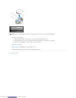
Page 149: ...10 Replace the computer cover Back to Contents Page 3 captive screw housing 2 ...

Page 150: ...he release button located on the floor of the computer chassis 6 Slide the power supply toward the front of the computer by approximately 1 inch 7 Lift the power supply up and out of the computer 8 Slide the replacement power supply into place 9 Replace the screws that secure the power supply to the back of the computer chassis 10 Reconnect the DC power cables CAUTION Before you begin any of the p...

Page 151: ... Pin Number Signal name 18 AWG Wire 1 3 3 VDC Orange 2 3 3 VDC Orange 3 GND Black 4 VCC 5 V Red 5 GND Black 6 VCC 5 V Red 7 GND Black 8 PS_PWRGOOD Gray 9 P5AUX Purple 10 V_12P0_DIG Yellow 11 V_12P0_DIG Yellow 12 3 3 V Orange 13 3 3 V Orange 14 12 V Blue 15 GND Black 16 PWR_PS_ON Green 17 GND Black 18 GND Black 19 GND Black 20 NC N C 21 VCC 5V Red ...

Page 152: ...Red 24 GND Black Use 22 AWG wire instead of 18 AWG wire Pin Number Signal Name 18 AWG Wire 1 COM Black 2 COM Black 3 12 VDC Yellow 4 12 VDC Yellow Pin Number Signal name 18 AWG Wire 1 12 VDC Yellow 2 COM Black 3 COM Black 4 5 VDC Red Pin Number Signal Name 22 AWG Wire 1 5 VCD Red 2 COM Black 3 COM Black 4 12 VDC Yellow ...

Page 153: ...Back to Contents Page Pin Number Signal name 18 AWG Wire 1 3 3 VDC Orange 2 COM Black 3 5 VDC Red 4 COM Black 5 12 VDC Yellow ...

Page 154: ...bits DMA channels eight Interrupt levels 24 BIOS chip NVRAM 4 Mb Memory speed 400 MHz and 533 MHz NIC integrated network interface with ASF 1 03 and 2 0 support as defined by DMTF Capable of 10 100 1000 communication l Green A good connection exists between a 10 Mbps network and the computer l Orange A good connection exists between a 100 Mbps network and the computer l Yellow A good connection ex...

Page 155: ...rnally accessible one bay for a 1 inch high hard drive Connectors External connectors Serial 9 pin connector 16550C compatible Parallel 25 hole connector bidirectional Video 15 hole VGA connector Network adapter RJ45 connector Optional PS 2 with secondary serial port adapter two 6 pin mini DINs USB two front panel and six back panel USB 2 0 compliant connectors Audio three connectors for line in l...

Page 156: ...e light for 100 Mb operation yellow light for a 1000 Mb 1 Gb operation Activity light on integrated network adapter yellow blinking light Diagnostic lights four lights on the back panel see Diagnostic Lights Standby power light AUX_PWR on the system board Power DC power supply Wattage 220 W Heat dissipation 751 BTU hr NOTE Heat dissipation is calculated based upon the power supply wattage rating V...

Page 157: ...Back to Contents Page ...

Page 158: ...using the slot provided near the bottom of the badge 4 LAN indicator light This light indicates that a LAN network connection is established 5 diagnostic lights Use these lights to help you troubleshoot a computer problem based on the diagnostic code For more information see Diagnostic Lights 6 hard drive activity light This light flickers when the hard drive is being accessed 7 power light The po...

Page 159: ...printer to the parallel connector If you have a USB printer plug it into a USB connector NOTE The integrated parallel connector is automatically disabled if the computer detects an installed card containing a parallel connector configured to the same address For more information see System Setup Options 2 link integrity light l Green A good connection exists between a 10 Mbps network and the compu...

Page 160: ...ogram On computers with a sound card the microphone connector is on the card 8 USB 2 0 connectors 6 Use the back USB connectors for devices that typically remain connected such as printers and keyboards 9 video connector Plug the cable from your VGA compatible monitor into the blue connector NOTE If you purchased an optional graphics card this connector will be covered by a cap Connect your monito...

Page 161: ... socket BATT 4 memory module connectors DIMM_1 and DIMM_2 13 PCI connector SLOT2 5 serial ATA drive connector SATA0 14 serial connector SER2 6 front panel connector FNT_PANEL 15 floppy drive connector DSKT 7 power connector POWER 16 standby power indicator AUX_PWR 8 CD DVD drive connector IDE 17 system board speaker BEEP 9 RTC reset jumper RTCRST 18 internal speaker INT_SPKR Small Form Factor Comp...

Page 162: ...Back to Contents Page default Password features are disabled RTCRST default The real time clock has not been reset The real time clock is being reset jumpered temporarily jumpered unjumpered ...

Page 163: ...ep 6 5 If you are replacing a card that is already installed in the computer remove the card If necessary disconnect any cables connected to the card If your card includes a card retention bar remove the bar Gently pull the securing tab grasp the card by its top corners and ease it out of its connector 6 Prepare the new card for installation See the documentation that came with the card for inform...

Page 164: ...cable to the integrated network connector on the back panel of the computer 14 Install any drivers required for the card as described in the card documentation Removing a PCI Card 1 Follow the procedures in Before You Begin 2 Gently push the release tab on the card retention latch from the inside to pivot the latch open Because the latch is captive it will remain in the open position 3 Use the car...

Page 165: ...ever 3 If necessary disconnect any cables connected to the adapter 4 Grasp the serial port adapter bracket by its top corners and ease it out of its connector 5 Replace the computer cover NOTE Installing filler brackets over empty card slot openings is necessary to maintain FCC certification of the computer The brackets also keep dust and dirt out of your computer NOTICE To connect a network cable...

Page 166: ...Back to Contents Page ...

Page 167: ...everage points 5 Remove the cover from the hinge tabs and set it aside on a soft nonabrasive surface Back to Contents Page CAUTION Before you begin any of the procedures in this section follow the safety instructions in the Product Information Guide CAUTION To guard against electrical shock always unplug your computer from the electrical outlet before removing the computer cover NOTICE Ensure that...

Page 168: ... cables a DC power cable and a data cable to the back of the drive and to the system board Drive Interface Connectors Most interface connectors are keyed for correct insertion that is a notch or a missing pin on one connector matches a tab or a filled in hole on the other connector Keyed connectors ensure that the pin 1 wire in the cable goes to the pin 1 end of the connector The pin 1 end of a co...

Page 169: ...at the system board is on the bottom of the inside of the computer 4 Press in on the two blue securing tabs on each side of the drive and slide the drive up and out of the computer NOTICE When you connect an IDE interface cable do not place the colored stripe away from pin 1 of the connector Reversing the cable prevents the drive from operating and could damage the controller the drive or both 1 p...

Page 170: ...r installation 3 If your replacement hard drive does not have the plastic drive bracket attached remove the bracket from the existing drive by unsnapping it from the drive NOTICE Do not pull the drive out of the computer by the drive cables Doing so may cause damage to cables and the cable connectors 1 securing tabs 2 2 hard drive 1 power cable 2 serial ATA data cable NOTICE To avoid damage to the...

Page 171: ...erly cabled and firmly seated 6 Gently position the drive until it clicks into place 7 Check all connectors to be certain that they are properly cabled and firmly seated 8 Replace the computer cover 1 drive 2 release tabs 2 3 hard drive bracket 1 power cable 2 serial ATA data cable 1 release tabs 2 2 hard drive ...

Page 172: ...ter on its side so that the system board is on the bottom of the inside of the computer 3 Remove the computer cover 4 Pull up on the drive release latch and slide the drive towards the back of the computer Then lift up to remove the drive from the computer 5 Disconnect the CD DVD drive cable from the system board connector labeled IDE CAUTION Before you begin any of the procedures in this section ...

Page 173: ...re the drive for the cable select setting 2 Connect the CD DVD drive cables to the drive 3 Lower the drive into the drive bracket and align the two drive bracket tabs with the holes on the side of the drive Then attach the two screws to the side to secure it 4 Gently position the drive until it clicks into place 5 Reconnect the CD DVD drive cable to the system board connector labeled IDE 1 screws ...

Page 174: ...side so that the system board is on the bottom of the inside of the computer 4 Remove the CD DVD drive and carefully set it aside 5 Pull up the cable release tab to unlock it and disconnect the floppy drive cable from the back of the floppy drive 6 Use the pull tab on the cable connector to disconnect the floppy drive cable from the system board CAUTION Before you begin any of the procedures in th...

Page 175: ...he drive until it clicks into place 3 Insert the floppy drive cable into the cable release tab on the floppy drive and press down on the tab until it clicks to lock it in place 4 Reconnect the data cable to the system board connector labeled DSKT 1 cable release tab 2 data cable edge connector 3 data cable pull tab NOTE In the event the replacement or new floppy drive does not have the shoulder sc...

Page 176: ...he fan and cooling vents 8 Replace the computer cover 9 Enter and use the Diskette Drive option to enable your new floppy drive See the documentation that came with the drive for instructions on installing any software required for drive operation 10 Verify that your computer works correctly by running the Dell Diagnostics Back to Contents Page 1 cable release tab 2 data cable edge connector 3 sys...

Page 177: ...emove the I O panel from the computer Replacing the I O Panel To replace the I O panel follow the removal procedures in the reverse order Back to Contents Page CAUTION Before you begin any of the procedures in this section follow the safety instructions located in the Product Information Guide CAUTION To guard against electrical shock always unplug your computer from the electrical outlet before r...

Page 178: ...ons located in the Product Information Guide NOTICE To prevent static damage to components inside your computer discharge static electricity from your body before you touch any of your computer s electronic components You can do so by touching an unpainted metal surface on the computer chassis CAUTION Despite having a plastic shield the heat sink assembly may be very hot during normal operation Be...

Page 179: ...alignment notches on the socket 5 Align the pin 1 corners of the processor and socket 1 center cover latch 2 processor cover 3 processor 4 socket 5 release lever NOTICE When replacing the processor do not touch any of the pins inside the socket or allow any objects to fall on the pins in the socket NOTICE Ground yourself by touching an unpainted metal surface on the back of the computer NOTICE Whe...

Page 180: ...l the heat sink assembly a Place the heat sink assembly back onto the heat sink assembly bracket b Rotate the heat sink assembly down towards the computer base and tighten the two captive screws 1 processor cover 6 release lever 2 tab 7 front alignment notch 3 processor 8 socket and processor pin 1 indicator 4 processor socket 9 rear alignment notch 5 center cover latch NOTICE To avoid damage ensu...

Page 181: ...10 Replace the computer cover Back to Contents Page 3 captive screw in housing 2 ...

Page 182: ...DMA channels eight Interrupt levels 24 BIOS chip NVRAM 4 Mb Memory speed 400 MHz and 533 MHz NIC integrated network interface with ASF 1 03 and 2 0 support as defined by DMTF Capable of 10 100 1000 communication l Green A good connection exists between a 10 Mbps network and the computer l Orange A good connection exists between a 100 Mbps network and the computer l Yellow A good connection exists ...

Page 183: ... 7 pin connector Floppy drive 34 pin connector Serial 12 pin connector for optional second serial port card Fan 5 pin connector PCI 2 2 120 pin connector CD drive audio interface 4 pin connector Front panel 40 pin connector Key Combinations Ctrl Alt Del in Microsoft Windows XP brings up the Windows Security window in MS DOS mode restarts reboots the computer F2 or Ctrl Alt Enter starts embedded sy...

Page 184: ...BTU hr NOTE Heat dissipation is calculated based upon the power supply wattage rating Voltage manual selection power supplies 90 to 135 V at 50 60 Hz 180 to 265 V at 50 60 Hz Backup battery 3 V CR2032 lithium coin cell Physical Height 9 26 cm 3 65 inches Width 31 37 cm 12 35 inches Depth 34 03 cm 13 40 inches Weight 7 4 kg 16 4 lb Environmental Temperature Operating 10 to 35 C 50 to 95 F Storage 4...

Page 185: ...n Agency As an ENERGY STAR partner Dell Inc has determined that this product meets the ENERGY STAR guidelines for energy efficiency Other trademarks and trade names may be used in this document to refer to either the entities claiming the marks and names or their products Dell Inc disclaims any proprietary interest in trademarks and trade names other than its own Model DCSM October 2006 P N W9246 ...

Page 186: ...er s instructions CAUTION Before you begin any of the procedures in this section follow the safety instructions located in the Product Information Guide Replace the battery If you have to repeatedly reset time and date information after turning on the computer or if an incorrect time or date displays during start up replace the battery If the battery still does not work properly contact Dell CAUTI...

Page 187: ...estart it 2 When F2 Setup appears in the upper right corner of the screen press Ctrl Alt d 3 Follow the instructions on the screen Run Check Disk 1 Click the Start button and click My Computer 2 Right click Local Disk C 3 Click Properties 4 Click the Tools tab 5 Under Error checking click Check Now 6 Click Scan for and attempt recovery of bad sectors 7 Click Start CAUTION Before you begin any of t...

Page 188: ...NOTICE You might lose data if you are unable to perform an operating system shutdown Turn the computer off If you are unable to get a response by pressing a key on your keyboard or moving your mouse press and hold the power button for at least 8 to 10 seconds until the computer turns off Then restart your computer End the program 1 Press Ctrl Shift Esc simultaneously 2 Click Applications 3 Click t...

Page 189: ...m See Beep Codes for more information CAUTION Before you begin any of the procedures in this section follow the safety instructions located in the Product Information Guide If you receive an insufficient memory message l Save and close any open files and exit any open programs you are not using to see if that resolves the problem l See the software documentation for minimum memory requirements If ...

Page 190: ...tware and hardware conflicts CAUTION Before you begin any of the procedures in this section follow the safety instructions located in the Product Information Guide Check the network cable connector Ensure that the network cable is firmly inserted into both the network connector on the back of the computer and the network jack Check the network lights on the front or back of the computer depending ...

Page 191: ...able is securely connected to the system board Eliminate interference Some possible causes of interference are l Power keyboard and mouse extension cables l Too many devices on a power strip l Multiple power strips connected to the same electrical outlet CAUTION Before you begin any of the procedures in this section follow the safety instructions located in the Product Information Guide NOTE If yo...

Page 192: ...ial port adapter installed or the LPT Port Mode setting matches the recommended settings Run the Dell Diagnostics CAUTION Before you begin any of the procedures in this section follow the safety instructions located in the Product Information Guide NOTE The volume control in some MP3 players overrides the Windows volume setting If you have been listening to MP3 songs ensure that you did not turn t...

Page 193: ...eadphones do not work if the CD drive is operating in digital mode 1 Click the Start button click Control Panel and then click Sounds Speech and Audio Devices 2 Click Sounds and Audio Devices 3 Click the Hardware tab 4 Double click the name of your CD drive 5 Click the Properties tab 6 Uncheck the Enable digital CD audio for this CD ROM device box Adjust the Windows volume control Click or double ...

Page 194: ...ctly Exit system setup and restart your computer Run the monitor self test Check the monitor documentation for more information Check the monitor settings See the monitor documentation for instructions on adjusting the contrast and brightness demagnetizing degaussing the monitor and running the monitor self test Move the subwoofer away from the monitor If your speaker system includes a subwoofer e...

Page 195: ...er s instructions CAUTION Before you begin any of the procedures in this section follow the safety instructions located in the Product Information Guide Replace the battery If you have to repeatedly reset time and date information after turning on the computer or if an incorrect time or date displays during start up replace the battery If the battery still does not work properly contact Dell CAUTI...

Page 196: ...estart it 2 When F2 Setup appears in the upper right corner of the screen press Ctrl Alt d 3 Follow the instructions on the screen Run Check Disk 1 Click the Start button and click My Computer 2 Right click Local Disk C 3 Click Properties 4 Click the Tools tab 5 Under Error checking click Check Now 6 Click Scan for and attempt recovery of bad sectors 7 Click Start CAUTION Before you begin any of t...

Page 197: ...NOTICE You might lose data if you are unable to perform an operating system shutdown Turn the computer off If you are unable to get a response by pressing a key on your keyboard or moving your mouse press and hold the power button for at least 8 to 10 seconds until the computer turns off Then restart your computer End the program 1 Press Ctrl Shift Esc simultaneously 2 Click Applications 3 Click t...

Page 198: ...m See Beep Codes for more information CAUTION Before you begin any of the procedures in this section follow the safety instructions located in the Product Information Guide If you receive an insufficient memory message l Save and close any open files and exit any open programs you are not using to see if that resolves the problem l See the software documentation for minimum memory requirements If ...

Page 199: ...tware and hardware conflicts CAUTION Before you begin any of the procedures in this section follow the safety instructions located in the Product Information Guide Check the network cable connector Ensure that the network cable is firmly inserted into both the network connector on the back of the computer and the network jack Check the network lights on the front or back of the computer depending ...

Page 200: ...able is securely connected to the system board Eliminate interference Some possible causes of interference are l Power keyboard and mouse extension cables l Too many devices on a power strip l Multiple power strips connected to the same electrical outlet CAUTION Before you begin any of the procedures in this section follow the safety instructions located in the Product Information Guide NOTE If yo...

Page 201: ...ial port adapter installed or the LPT Port Mode setting matches the recommended settings Run the Dell Diagnostics CAUTION Before you begin any of the procedures in this section follow the safety instructions located in the Product Information Guide NOTE The volume control in some MP3 players overrides the Windows volume setting If you have been listening to MP3 songs ensure that you did not turn t...

Page 202: ...eadphones do not work if the CD drive is operating in digital mode 1 Click the Start button click Control Panel and then click Sounds Speech and Audio Devices 2 Click Sounds and Audio Devices 3 Click the Hardware tab 4 Double click the name of your CD drive 5 Click the Properties tab 6 Uncheck the Enable digital CD audio for this CD ROM device box Adjust the Windows volume control Click or double ...

Page 203: ...ctly Exit system setup and restart your computer Run the monitor self test Check the monitor documentation for more information Check the monitor settings See the monitor documentation for instructions on adjusting the contrast and brightness demagnetizing degaussing the monitor and running the monitor self test Move the subwoofer away from the monitor If your speaker system includes a subwoofer e...

Page 204: ...Protection Agency As an ENERGY STAR partner Dell Inc has determined that this product meets the ENERGY STAR guidelines for energy efficiency Other trademarks and trade names may be used in this document to refer to either the entities claiming the marks and names or their products Dell Inc disclaims any proprietary interest in trademarks and trade names other than its own Model DCTR October 2006 P...

Page 205: ...of Microsoft Corporation IBM is a registered trademark of International Business Machines Corporation Bluetooth is a trademark owned by Bluetooth SIG Inc and is used by Dell Inc under license ENERGY STAR is a registered trademark of the U S Environmental Protection Agency As an ENERGY STAR partner Dell Inc has determined that this product meets the ENERGY STAR guidelines for energy efficiency Othe...

Page 206: ...n your computer and try again 3 When the boot device list appears highlight Boot to Utility Partition and press Enter 4 When the Dell Diagnostics Main Menu appears select the test you want to run Starting the Dell Diagnostics From the Drivers and Utilities CD Optional 1 Insert the Drivers and Utilities CD optional 2 Shut down and restart the computer When the DELL logo appears press F12 immediatel...

Page 207: ... want to run Symptom Tree Lists the most common symptoms encountered and allows you to select a test based on the symptom of the problem you are having NOTE The Service Tag for your computer is located at the top of each test screen If you contact Dell technical support will ask for your Service Tag Your computer s Service Tag is listed in the System Info option in system setup Tab Function Result...

Page 208: ...r button A possible BIOS failure has occurred the computer is in the recovery mode Run the BIOS Recovery utility wait for recovery completion and then restart the computer A possible processor failure has occurred Reinstall the processor and restart the computer Memory modules are detected but a memory failure has occurred l If you have one memory module installed reinstall it and restart the comp...

Page 209: ...ition None Light Pattern Problem Description Suggested Resolution Code Cause 1 1 2 Microprocessor register failure 1 1 3 NVRAM read write failure 1 1 4 ROM BIOS checksum failure 1 2 1 Programmable interval timer failure 1 2 2 DMA initialization failure 1 2 3 DMA page register read write failure 1 3 Video Memory test failure 1 3 1 through 2 4 4 Memory not being properly identified or used 3 1 1 Sla...

Page 210: ... attempts at booting this system have failed at checkpoint nnnn For help in resolving this problem please note this checkpoint and contact Dell Technical Support Contact Dell and report the checkpoint code nnnn to the support technician Attachment failed to respond See Drive Problems Bad command or file name Ensure that you spelled the command correctly put spaces in the proper place and used the ...

Page 211: ...ard drive is your boot device ensure that the cables are connected and that the drive is installed properly and partitioned as a boot device l Enter system setup and ensure that the boot sequence information is correct No boot sector on hard disk drive Enter system setup and ensure that the computer configuration information for the hard drive is correct No timer tick interrupt Run the Dell Diagno...

Page 212: ... failure Run the Dell Diagnostics Time of day clock stopped Time of day not set please run the System Setup program Enter system setup and correct the date or time If the problem persists replace the battery Timer chip counter 2 failed Run the Dell Diagnostics Unexpected interrupt in protected mode Run the Dell Diagnostics WARNING Dell s Disk Monitoring System has detected that drive 0 1 on the pr...

Page 213: ...es window reports the devices that need to be re configured 6 Reconfigure the devices or remove the devices from the Device Manager See the documentation that came with the device for information on configuring the device To resolve incompatibilities using the Windows XP Hardware Troubleshooter 1 Click the Start button and click Help and Support 2 Type hardware troubleshooter in the Search field a...

Page 214: ...ft Windows desktop Then shut down your computer and try again 3 When the boot device list appears highlight Boot to Utility Partition and press Enter 4 When the Dell Diagnostics Main Menu appears select the test you want to run Starting the Dell Diagnostics From the Drivers and Utilities CD Optional 1 Insert the Drivers and Utilities CD optional 2 Shut down and restart the computer When the DELL l...

Page 215: ...om Test Tests a specific device You can customize the tests you want to run Symptom Tree Lists the most common symptoms encountered and allows you to select a test based on the symptom of the problem you are having NOTE The Service Tag for your computer is located at the top of each test screen If you contact Dell technical support will ask for your Service Tag Your computer s Service Tag is liste...

Page 216: ...ical outlet and press the power button A possible BIOS failure has occurred the computer is in the recovery mode Run the BIOS Recovery utility wait for recovery completion and then restart the computer A possible processor failure has occurred Reinstall the processor and restart the computer Memory modules are detected but a memory failure has occurred l If you have one memory module installed rei...

Page 217: ...ition None Light Pattern Problem Description Suggested Resolution Code Cause 1 1 2 Microprocessor register failure 1 1 3 NVRAM read write failure 1 1 4 ROM BIOS checksum failure 1 2 1 Programmable interval timer failure 1 2 2 DMA initialization failure 1 2 3 DMA page register read write failure 1 3 Video Memory test failure 1 3 1 through 2 4 4 Memory not being properly identified or used 3 1 1 Sla...

Page 218: ... attempts at booting this system have failed at checkpoint nnnn For help in resolving this problem please note this checkpoint and contact Dell Technical Support Contact Dell and report the checkpoint code nnnn to the support technician Attachment failed to respond See Drive Problems Bad command or file name Ensure that you spelled the command correctly put spaces in the proper place and used the ...

Page 219: ...oot device ensure that a bootable floppy disk is in the drive l If the hard drive is your boot device ensure that the cables are connected and that the drive is installed properly and partitioned as a boot device l Enter system setup and ensure that the boot sequence information is correct No boot sector on hard disk drive Enter system setup and ensure that the computer configuration information f...

Page 220: ...ard drive Seek error See Drive Problems Shutdown failure Run the Dell Diagnostics Time of day clock stopped Time of day not set please run the System Setup program Enter system setup and correct the date or time If the problem persists replace the battery Timer chip counter 2 failed Run the Dell Diagnostics Unexpected interrupt in protected mode Run the Dell Diagnostics WARNING Dell s Disk Monitor...

Page 221: ...atus area in the Properties window reports the devices that need to be re configured 6 Reconfigure the devices or remove the devices from the Device Manager See the documentation that came with the device for information on configuring the device To resolve incompatibilities using the Windows XP Hardware Troubleshooter 1 Click the Start button and click Help and Support 2 Type hardware troubleshoo...

Page 222: ...Back to Contents Page Dell OptiPlex GX520 User s Guide Back to Contents Page ...

Page 223: ...are products from parts and components that are new or equivalent to new in accordance with industry standard practices For information about the Dell warranty for your computer see the Product Information Guide or separate paper warranty document that shipped with your computer Back to Contents Page ...

Page 224: ...CD and click Next 5 When the Now go to your old computer screen appears go to your old or source computer Do not click Next at this time To copy data from the old computer 1 On the old computer insert the Windows XP Operating System CD 2 On the Welcome to Microsoft Windows XP screen click Perform additional tasks 3 Under What do you want to do click Transfer files and settings 4 On the Files and S...

Page 225: ...oftware might not work with Fast User Switching For more information see the Windows Help and Support Center Setting Up a Home and Office Network Connecting to a Network Adapter Before you connect your computer to a network the computer must have a network adapter installed and a network cable connected to it To connect a network cable 1 Connect the network cable to the network adapter connector o...

Page 226: ...ext 3 Click Checklist for creating a network 4 Complete the checklist and required preparations 5 Return to the Network Setup Wizard and follow the instructions on the screen Back to Contents Page NOTE Selecting the connection method This computer connects directly to the Internet enables the integrated firewall provided with Windows XP SP1 ...

Page 227: ...CD and click Next 5 When the Now go to your old computer screen appears go to your old or source computer Do not click Next at this time To copy data from the old computer 1 On the old computer insert the Windows XP Operating System CD 2 On the Welcome to Microsoft Windows XP screen click Perform additional tasks 3 Under What do you want to do click Transfer files and settings 4 On the Files and S...

Page 228: ...oftware might not work with Fast User Switching For more information see the Windows Help and Support Center Setting Up a Home and Office Network Connecting to a Network Adapter Before you connect your computer to a network the computer must have a network adapter installed and a network cable connected to it To connect a network cable 1 Connect the network cable to the network adapter connector o...

Page 229: ...ext 3 Click Checklist for creating a network 4 Complete the checklist and required preparations 5 Return to the Network Setup Wizard and follow the instructions on the screen Back to Contents Page NOTE Selecting the connection method This computer connects directly to the Internet enables the integrated firewall provided with Windows XP SP1 ...

Reviews: