background image

Dell PowerEdge VRTX Enclosure
Owner's Manual

Regulatory Model: E22S

Regulatory Type: E22S001

Summary of Contents for PowerEdge M520

Page 1: ...Dell PowerEdge VRTX Enclosure Owner s Manual Regulatory Model E22S Regulatory Type E22S001 ...

Page 2: ...problem WARNING A WARNING indicates a potential for property damage personal injury or death Copyright 2014 Dell Inc All rights reserved This product is protected by U S and international copyright and intellectual property laws Dell and the Dell logo are trademarks of Dell Inc in the United States and or other jurisdictions All other marks and names mentioned herein may be trademarks of their res...

Page 3: ...s 28 I O Module Indicators 29 CMC Indicators 30 CMC Features 30 CMC Fail Safe Mode 31 Configuration Wizard 31 System Messages 32 LCD Messages 32 Related Documentation 32 Quick Resource Locator 33 2 Initial System Configuration 35 Before You Begin 35 Initial Setup Sequence 35 Logging In To The CMC 36 3 Configuring Enclosure Components 37 Fabric A 37 Fabrics B And C 37 I O Module And PCIe Mezzanine ...

Page 4: ...Removing A 3 5 Inch Hard Drive Blank 50 Installing A 3 5 Inch Hard Drive Blank 51 Removing A Hot Swap Hard Drive 51 Installing A Hot Swap Hard Drive 52 Removing A Hard Drive From A Hard Drive Carrier 53 Installing A Hard Drive Into A Hard Drive Carrier 54 Server Modules 54 Removing A Server Module 55 Configuring A Server Module 57 Installing A Server Module 58 Server Module Partitions 58 Removing ...

Page 5: ...Ie Cage 85 Expansion Cards 85 Expansion Card Installation Guidelines 85 Expansion Card Operational Power Status 86 PCIe Slot Indicators 87 Removing A Low Profile Expansion Card 88 Installing A Low Profile Expansion Card 89 Removing The Low Profile Expansion Card Divider Unit 90 Installing The Low Profile Expansion Card Divider Unit 91 Removing A Full Height Expansion Card 92 Installing A Full Heig...

Page 6: ...Expander Boards 117 Removing A Backplane Expander Board 117 Installing A Backplane Expander Board 118 Hard Drive Backplane 119 Removing The Hard Drive Backplane 119 Installing The Hard Drive Backplane 121 Power Distribution Board 122 Removing The Power Distribution Board 122 Installing The Power Distribution Board 124 System Board 125 Removing The System Board 125 Installing The System Board 127 P...

Page 7: ...eshooting The System Battery 143 Troubleshooting Cooling Problems 144 Troubleshooting Cooling Fans 144 Troubleshooting An Optical Drive 144 Troubleshooting A Storage Controller 145 Troubleshooting Hard Drives 145 Troubleshooting Expansion Cards 146 Troubleshooting The I O Module 146 7 System Board Connectors 149 8 Technical Specifications 153 Enclosure Specifications 153 I O Module Specifications ...

Page 8: ...8 ...

Page 9: ...installed in the chassis PCIe mezzanine card s Server modules configured for the VRTX enclosure have PCIe mezzanine cards installed in Fabrics B and C to provide I O expansion NOTE Ethernet Fibre Channel or InfiniBand mezzanine cards are not supported on the VRTX enclosure PCIe expansion card s PCIe cards installed in the enclosure provide I O expansion to the chassis Warm plug A slot is considere...

Page 10: ...losure 1 PCIe label on the server module 2 server module 3 VRTX enclosure If you install server modules that are not configured for the enclosure an error message is displayed The enclosure supports power supplies hard drives Chassis Management Controllers CMC blower modules and an I O module These are shared resources for the server modules NOTE To ensure proper operation and cooling all bays in ...

Page 11: ...Server Module And Hard Drive Numbering Tower Mode Figure 2 Half Height Server Module and Hard Drive Numbering 2 5 Inch Hard Drive Chassis 1 server module numbering 2 hard drive numbering 11 ...

Page 12: ...Figure 3 Full Height Server Module and Hard Drive Numbering 2 5 Inch Hard Drive Chassis 1 server module numbering 2 hard drive numbering 12 ...

Page 13: ...Figure 4 Server Module Half Height and Full Height Server Modules and Hard Drive Numbering 2 5 Inch Hard Drive Chassis 1 server module numbering 2 hard drive numbering 13 ...

Page 14: ...d Hard Drive Numbering 3 5 Inch Hard Drive Chassis 1 server module numbering 2 hard drive numbering Figure 6 Full Height Server Module and Hard Drive Numbering 3 5 Inch Hard Drive Chassis 1 server module numbering 2 hard drive numbering 14 ...

Page 15: ...Figure 7 Server Module Half Height and Full Height Server Modules and Hard Drive Numbering 3 5 Inch Hard Drive Chassis 1 server module numbering 2 hard drive numbering 15 ...

Page 16: ...Server Module And Hard Drive Numbering Rack Mode Figure 8 Half Height Server Module and Hard Drive Numbering 2 5 Inch Hard Drive Chassis 1 server module numbering 2 hard drive numbering 16 ...

Page 17: ...odule and Hard Drive Numbering 2 5 Inch Hard Drive Chassis 1 server module numbering 2 hard drive numbering Figure 10 Server Module Half Height and Full Height Server Modules and Hard Drive Numbering 2 5 Inch Hard Drive Chassis 17 ...

Page 18: ...d Hard Drive Numbering 3 5 Inch Hard Drive Chassis 1 server module numbering 2 hard drive numbering Figure 12 Full Height Server Module and Hard Drive Numbering 3 5 Inch Hard Drive Chassis 1 server module numbering 2 hard drive numbering 18 ...

Page 19: ...Figure 13 Server Module Half Height and Full Height Server Modules and Hard Drive Numbering 3 5 Inch Hard Drive Chassis 1 server module numbering 2 hard drive numbering 19 ...

Page 20: ...Front Panel Features And Indicators Figure 14 Front Panel Features And Indicators 2 5 Inch Hard Drive Chassis 20 ...

Page 21: ...stem is operating correctly or when the system needs attention 3 LCD menu scroll buttons 4 Moves the cursor in one step increments 4 Selection check button Selects and saves an item on the LCD screen and moves to the next screen 5 Enclosure power on indicator power button The power on indicator lights when the enclosure power is on The power button controls the power supply output to the system 6 ...

Page 22: ...cted to the system 11 Server modules Up to four PowerEdge M520 or M620 server modules or up to two M820 server modules specifically configured for the enclosure KVM Features Local KVM access can be remotely disabled on a per server module basis using the server module iDRAC interface access is enabled by default One VGA connector The KVM supports a video display resolution range from 640 480 at 60...

Page 23: ...ive rebuilding Steady green Drive online Blinks green three seconds amber three seconds and off six seconds Rebuild aborted LCD Module You can use the LCD panel on the enclosure chassis to perform configuration and diagnostics and to obtain status information about the chassis and its contents Figure 17 LCD Display 1 LCD screen 2 selection check button 3 scroll buttons 4 LCD Module Features The pr...

Page 24: ...lect and save an item and move to the next screen Main Menu From the Main menu you can navigate to one of the following screens Screen Description LCD Setup Contains the options such as Language Setup LCD Orientation and the Default Screen KVM Mapping Contains the options to map or unmap the KVM to the servers DVD Mapping Contains the option to map or unmap the DVD drive on the chassis to the serv...

Page 25: ...t Status Rear Side Enclosure status Use the navigation buttons to highlight the desired item highlight the Back icon to return to the Main menu and press the center button The selected screen is displayed IP Summary Menu The IP Summary screen displays the IP information for CMC IPv4 and IPv6 and iDRAC IPv4 and IPv6 on each of the installed servers Use the up and down arrow buttons to scroll throug...

Page 26: ...full height 3 Allows you to connect up to three full height PCI Express expansion cards 3 CMC GbE port 2 Connects the network cable from the management system to the secondary CMC 4 CMC GbE port 1 Connects the network cable from the management system to the primary CMC 5 Serial connector DB 9 serial connector for CMC configuration 6 Blower modules 4 Provide cooling for the server modules 7 I O mod...

Page 27: ...andby mode the handle lights green indicating that a valid power source is connected to the power supply and that the power supply is operational Flashing amber Indicates a problem with the power supply CAUTION When correcting a power supply mismatch replace only the power supply with the flashing indicator Swapping the opposite power supply to make a matched pair can result in an error condition ...

Page 28: ...e indicators provide the following information Indicator Description Blower module power indicator Steady Green The blower module is receiving power Off The blower module is not receiving power Blower module fault indicator Blinking Amber The blower module is in a fault condition Off The blower module is operating normally 28 ...

Page 29: ...n The I O module is operating normally Off The I O module is powered off Status indicator Blue The I O module is operating normally Blinking Blue The CMC is identifying the I O module Blinking Amber The I O module is in a fault condition Off The I O module is powered off or booting is in progress For more information see the I O module documentation at dell com poweredgemanuals 29 ...

Page 30: ...l time automatic power and thermal management Monitors system power requirements and supports the optional Dynamic Power Supply Engagement DPSE mode The DPSE mode improves power efficiency by allowing the CMC to dynamically place power supplies in standby mode depending on the load and redundancy requirements Reports real time power consumption which includes logging high and low points with a tim...

Page 31: ...MC CMC network cable removal or network connection loss Chassis management resumes after the chassis fails over to the standby CMC Network failover is only enabled in redundant CMC mode CMC reset Chassis management resumes after the CMC reboots or chassis fails over to the standby CMC CMC failover command issued Chassis management resumes after the chassis fails over to the standby CMC CMC firmwar...

Page 32: ...r the iDRAC using the LCD configuration wizard To set a static IP address use the CMC web based interface or Remote Access Controller Administrator RACADM 6 Review the settings on the Network Summary screen If the settings are correct press the center button to close the configuration wizard and return to the Main Menu If the settings are not correct use the left arrow key to return to the screen ...

Page 33: ...Guide provides information on the error and event messages generated by the firmware or other agents that monitor system components This document is available at dell com esmmanuals The CMC Online Help provides information and instructions for the current page on the CMC web interface To access the Online Help click Help on the CMC web interface The Integrated Dell Remote Access Controller iDRAC U...

Page 34: ...34 ...

Page 35: ...nd iDRAC firmware on the server module s Download the latest version of CMC firmware from dell com support Also make sure that you have the Dell Systems Management Tools and Documentation DVD that was included with your system If your network uses static addressing you need the IP address subnet mask and gateway to configure the CMC and other modules in the enclosure Initial Setup Sequence CAUTION...

Page 36: ...For a detailed description on configuring the CMC settings see the Dell Chassis Management Controller for Dell PowerEdge VRTX User s Guide at dell com esmmanuals 7 Connect to the CMC IP address through the Web browser using the default logon credentials The default user name is root and password is calvin 8 Provide each iDRAC with an IP address in the CMC Web interface and enable the LAN and IPMI ...

Page 37: ...es integrated on the system board to connect the server modules to the Shared PoweEdge RAID Controller PERC card slots and eight PCIe expansion card slots on the enclosure NOTE To locate the Shared PERC card slots and the PCIe slots on the enclosure system board see System Board Connectors The PCIe switch mapping to the PCIe card slots is dependent on the firmware and the software license installe...

Page 38: ...uring the network settings for the I O module make sure the I O module is turned on To configure the network setting you must have Administrator privileges for Fabric A to configure the I O module in Group A You can configure the network settings using the following CMC web interface RACADM For more information on configuring the network settings see the Dell Chassis Management Controller for Dell...

Page 39: ...C cards on each server module are mapped to the PCIe switches which further map to the PCIe slots and the Shared PERC slots on the enclosure s system board NOTE For information on the specifications of the supported PCIe cards see Technical Specifications Figure 23 Mapping PCIe Expansion Slots Half Height Server Modules Figure 24 Mapping PCIe Expansion Slots Full Height Server Modules Managing PCI...

Page 40: ...l Disk VD or multiple VDs that are located on the shared storage For more information on the Shared PERC cards see the Dell Shared PowerEdge RAID Controller 8 User s Guide at dell com poweredgemanuals You can perform the following tasks related to the enclosure storage View the status of physical disks and storage controllers View the properties of controllers physical disks virtual disks and encl...

Page 41: ...pectively NOTE To ensure proper operation and cooling all bays in the enclosure must be populated at all times with either a module or with a blank NOTE It is recommended that you remove the front bezel server modules hard drives and power supplies from the chassis to reduce weight before laying the enclosure on its side Recommended Tools You may need the following items to perform the procedures ...

Page 42: ...at the top of the bezel toward the right 4 Move the top end of the bezel away from the system 5 Unhook the bezel tabs from the slots on the front of the chassis System Feet Tower Mode The system feet provide stability to the system in the tower mode Removing The System Feet 1 To reduce the chassis weight remove the following if required a Front bezel if installed b Hard drives See Removing A Hot S...

Page 43: ...flat stable surface and rotate the system feet outward 4 If removed reinstall the hard drives server modules power supplies and front bezel Wheel Assembly Optional Tower Mode The wheel assembly provides mobility to the system in the tower mode The wheel assembly consists of the following Wheel assembly units front and back Power cable retention bracket Installing The Wheel Assembly WARNING Wheneve...

Page 44: ... system base cover 6 Tighten the screw on the front wheel plate to secure it to the system base cover 7 Tilting the back wheel plate toward the hooks on the system base cover align the metal stand on the wheel plate with the hooks 8 Insert the metal stand on the back wheel plate into the hooks until firmly seated 9 Lower the other end of the back wheel plate to the chassis base and align the slot ...

Page 45: ...bles through the power cable retention bracket Figure 27 Removing and Installing the Wheel Assembly 1 hooks for the metal stands 4 2 metal stands 2 3 back wheel plate 4 front wheel plate 5 screws 2 6 tabs on system base cover 4 45 ...

Page 46: ...nd away from the chassis 4 To reduce the chassis weight remove the following if required a Front bezel if installed b Hard drives See Removing A Hot Swap Hard Drive c Server modules See Removing A Server Module d Power supplies See Removing A Power Supply 5 Lay the enclosure on a sturdy stable surface with the cover release latch side on top and the base of the enclosure extending slightly off the...

Page 47: ...ion for the system Failure to install the feet poses the risk of having the system tip over possibly causing damage to the system or bodily injury NOTE It is recommended that you always use a static mat and static strap while working on components in the interior of the system NOTE To replace hot swappable components inside the enclosure you do not need to turn off the enclosure or lay it on its s...

Page 48: ...rface and rotate the system feet outward 6 If removed reinstall the hard drives server modules and power supplies 7 Reconnect the enclosure to its electrical outlet and turn the enclosure on including any attached peripherals 8 Turn on the server modules using the operating system commands or the CMC 9 If applicable install the front bezel Inside The System CAUTION Many repairs may only be done by...

Page 49: ...drive backplane Hard Drives The 3 5 inch hard drive enclosure supports up to twelve hot swappable 3 5 inch hard drives The 2 5 inch hard drive enclosure supports up to twenty five hot swappable 2 5 inch hard drives All hard drives connect to the system board through the hard drive backplane Hard drives are supplied in hot swappable hard drive carriers that fit in the hard drive slots Use only hard...

Page 50: ... the hard drive slot Figure 31 Removing and Installing a 2 5 Inch Hard Drive Blank 1 hard drive blank 2 release button Installing A 2 5 Inch Hard Drive Blank 1 If installed remove the front bezel 2 Insert the hard drive blank into the hard drive slot until the release button clicks into place 3 If applicable install the front bezel Removing A 3 5 Inch Hard Drive Blank CAUTION To maintain proper sy...

Page 51: ... CAUTION To prevent data loss ensure that your operating system supports hot swap drive installation See the documentation supplied with your operating system 1 If installed remove the front bezel 2 From the management software prepare the hard drive for removal Wait until the indicators on the hard drive carrier signal that the hard drive can be removed safely For more information see the documen...

Page 52: ...the partially installed carrier s shield spring and make it unusable CAUTION To prevent data loss ensure that your operating system supports hot swap drive installation See the documentation supplied with your operating system CAUTION When a replacement hot swappable hard drive is installed and the system is powered on the hard drive automatically begins to rebuild Make absolutely sure that the re...

Page 53: ...For the 2 5 inch hard drive turn the hard drive carrier upside down and remove the screws from the side rails on the hard drive carrier 2 Lift the hard drive out of the hard drive carrier Figure 34 Removing and Installing a 2 5 Inch Hard Drive Into a Hard Drive Carrier 1 hard drive carrier 2 hard drive 3 screws 4 53 ...

Page 54: ... end of the hard drive toward the back 2 Align the screw holes on the hard drive with the set of screw holes on the hard drive carrier When aligned correctly the back of the hard drive is flush with the back of the hard drive carrier 3 Attach the screws to secure the hard drive to the hard drive carrier Server Modules NOTE Your system supports Dell PowerEdge M520 M620 and M820 server modules that ...

Page 55: ... out the server module handle to unlock the server module from the enclosure CAUTION If you are permanently removing the server module install a server module blank s Operating the system for an extended period of time without a server module blank installed can cause the enclosure to overheat 5 Slide the server module out of the enclosure CAUTION To protect the I O connector pins install the I O ...

Page 56: ... the I O connector cover s over the I O connector s Figure 36 Removing and Installing the I O Connector Cover 1 I O connector cover NOTE There are two I O connector covers on the PowerEdge M820 server module 56 ...

Page 57: ...le is identical to removing and installing a half height server module Configuring A Server Module NOTE Follow this procedure to install PowerEdge M520 M620 or M820 server modules that are not configured for the VRTX enclosure NOTE If you install PowerEdge M520 M620 or M820 server modules that are not configured for the VRTX enclosure an error message is displayed To configure a server module for ...

Page 58: ...ht server module s you must remove the server module partitions For more information see Removing The Server Module Partitions 1 If you are installing a new server module remove the plastic cover s from the I O connector s and save for future use 2 If applicable configure the server module For more information see Configuring A Server Module 3 Orient the server module so that the module handle is ...

Page 59: ...ation or as directed by the online or telephone service and support team Damage due to servicing that is not authorized by Dell is not covered by your warranty Read and follow the safety instructions that came with the product NOTE You must remove the server module partitions to install full height server modules 1 If installed remove the front bezel 2 Turn off the server modules using the operati...

Page 60: ...until it stops sliding The tabs on the partition move to unlock position c Rotate the partition upward in the counter clockwise direction to disengage the tabs from the slots on the metal partition d Slide the partition out from the system and save for future use Figure 39 Removing and Installing the Server Module Partition Between Slots 1 and 3 1 locking tab on server module partition 2 server mo...

Page 61: ...the tabs from the slots on the metal partition d Slide the partition out from the system and save for future use Figure 40 Removing and Installing the Server Module Partition Between Slots 2 and 4 1 metal partition 2 server module partition 3 tabs on the server module partition 4 slots on the inner chassis wall 5 locking tab on server module partition 6 inner chassis wall 7 Install the server modu...

Page 62: ...e electrical outlet and peripherals 4 Remove the server modules or server module blanks 5 To install the server module partition between Slots 1 and 3 a Angle the partition and slide it into the chassis b Align the tabs on the partition with the slots on the outer chassis wall and insert the tabs into the slots c Rotate the partition downward in the clockwise direction until the tabs on the other ...

Page 63: ...nd 4 1 metal partition 2 tabs on server module partition 3 slots on the metal partition 4 slots on the inner chassis wall 5 tabs on the server module partition 6 inner chassis wall 7 Install the server modules 8 Reconnect the enclosure to its electrical outlet and turn the enclosure on including any attached peripherals 9 Turn on the server modules using the operating system commands or the CMC 10...

Page 64: ...wer supply bay and insert it into the chassis until it clicks into place Removing A Power Supply CAUTION Many repairs may only be done by a certified service technician You should only perform troubleshooting and simple repairs as authorized in your product documentation or as directed by the online or telephone service and support team Damage due to servicing that is not authorized by Dell is not...

Page 65: ... intend to remove a In systems without the wheel assembly installed remove the power cable from the cable strap b In systems with the wheel assembly installed remove the power cable from the power cable retention bracket slot 2 Press the release latch and slide the power supply out of the chassis Figure 44 Removing and Installing a Power Supply 1 connector 2 power supply 3 power supply handle 4 re...

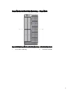
Page 66: ...Figure 45 Securing the Power Cable Without Wheel Assembly 1 power cable 2 strap 66 ...

Page 67: ...pply blank 2 Slide the new power supply into the enclosure until the power supply is fully seated and the release latch snaps into place 3 Connect the power cable to the power supply and plug the cable into a power outlet a In systems without the wheel assembly installed secure the power cable with the strap b In systems with the wheel assembly installed route the power cable from the power supply...

Page 68: ...te your system with the cooling shroud removed The system may get overheated quickly resulting in shutdown of the system and loss of data 1 If installed remove the front bezel 2 Turn off the server modules using the operating system commands or the CMC 3 Turn off the enclosure including any attached peripherals and disconnect the enclosure from the electrical outlet and peripherals 4 To reduce the...

Page 69: ...r warranty Read and follow the safety instructions that came with the product 1 Align the slot on the cooling shroud with the pin on the cooling fan assembly When aligned the slots on the other edge of the shroud align with the release pins on the hard drive backplane 2 Lower the cooling shroud into the chassis 3 Press down the shroud over the release pins on the hard drive backplane until it is f...

Page 70: ... removing or installing cooling fans WARNING The cooling fan can continue to spin for some time after it has been powered down Allow time for the fan to stop spinning before removing it from the system CAUTION Many repairs may only be done by a certified service technician You should only perform troubleshooting and simple repairs as authorized in your product documentation or as directed by the o...

Page 71: ...h the product 1 Align the plug at the base of the cooling fan with the connector on the system board 2 Slide the cooling fan into the securing slots until the tabs lock into place 3 Close the system Cooling Fan Assembly Removing The Cooling Fan Assembly CAUTION Many repairs may only be done by a certified service technician You should only perform troubleshooting and simple repairs as authorized i...

Page 72: ...e surface with the cover release latch side on top 6 Open the system 7 Remove the cooling shroud 8 Unlock the cooling fan assembly from the chassis by rotating the release levers upward 9 Lift the cooling fan assembly out of the chassis Figure 49 Removing and Installing the Cooling Fan Assembly 1 release levers 2 2 cooling fan assembly 3 cooling fans 6 4 cooling fan connectors 6 5 support brackets...

Page 73: ...10 If applicable install the front bezel Blower Modules Your system supports four hot swappable blower modules to ensure proper cooling of the server modules To provide increased cooling for the server modules in the enclosure you can set the blower configuration to the Enhanced Cooling Mode in the CMC web interface For more information on the Enhanced Cooling Mode option see Advanced Fan Configur...

Page 74: ...ple repairs as authorized in your product documentation or as directed by the online or telephone service and support team Damage due to servicing that is not authorized by Dell is not covered by your warranty Read and follow the safety instructions that came with the product CAUTION Exercise care while handling the blower module to prevent damage to the connector on the blower module CAUTION The ...

Page 75: ...g the operating system commands or the CMC 3 Turn off the enclosure including any attached peripherals and disconnect the enclosure from the electrical outlet and peripherals 4 Remove the four blower modules 5 Loosen the four screws securing the blower module bay to the chassis 6 Pull the blower module bay out of the chassis Figure 51 Removing and Installing the Blower Module Bay 1 blower module b...

Page 76: ...he CMC 6 If applicable install the front bezel I O Module Removing The I O Module CAUTION Many repairs may only be done by a certified service technician You should only perform troubleshooting and simple repairs as authorized in your product documentation or as directed by the online or telephone service and support team Damage due to servicing that is not authorized by Dell is not covered by you...

Page 77: ... documentation of the I O module for information about its cable connections Optical Drive Optional Removing The Optical Drive CAUTION Many repairs may only be done by a certified service technician You should only perform troubleshooting and simple repairs as authorized in your product documentation or as directed by the online or telephone service and support team Damage due to servicing that is...

Page 78: ...rd and connect the SAS cables See Installing The Backplane Expander Board For the 3 5 inch hard drive chassis reinstall the hard drive backplane See Installing The Hard Drive Backplane 16 Reinstall the cooling fan assembly 17 Reinstall the cooling shroud 18 Close the system 19 If applicable place the system upright on a flat stable surface and rotate the system feet outward 20 If removed reinstall...

Page 79: ...e chassis remove the hard drives and the hard drive backplane See Removing The Hard Drive Backplane 10 To remove the optical drive blank press the blue release tab at the back of the blank and push the blank out of the system 11 Align the optical drive with the optical drive slot on the front of the enclosure 12 Slide the optical drive into the slot until the latch snaps into place 13 Connect the ...

Page 80: ...guration only the power indicator is enabled on the standby CMC Removing A CMC Card CAUTION Many repairs may only be done by a certified service technician You should only perform troubleshooting and simple repairs as authorized in your product documentation or as directed by the online or telephone service and support team Damage due to servicing that is not authorized by Dell is not covered by y...

Page 81: ...le repairs as authorized in your product documentation or as directed by the online or telephone service and support team Damage due to servicing that is not authorized by Dell is not covered by your warranty Read and follow the safety instructions that came with the product 1 Align the CMC card with the card support bracket and holding the release tabs slide it down the bracket 2 Lower the CMC ca...

Page 82: ...ervicing that is not authorized by Dell is not covered by your warranty Read and follow the safety instructions that came with the product 1 Open the system 2 Locate the PCIe cage door release tab on the PCIe cage 3 Push the release tab toward the front of the system and lift the cage door from the enclosure 4 Angle the cage door and slide it toward the back of the system to disengage the tabs on ...

Page 83: ... or telephone service and support team Damage due to servicing that is not authorized by Dell is not covered by your warranty Read and follow the safety instructions that came with the product NOTE If the system is in the rack mode the rack door may prevent the removal and installation of the PCIe cage 1 If installed remove the front bezel 2 Turn off the server modules using the operating system c...

Page 84: ... and away from the chassis Figure 57 Removing and Installing the PCIe Cage 1 metal standoffs 2 2 screws 2 3 release latch 4 PCIe cage 5 guide pin 6 expansion card riser connectors 2 7 metal tabs on the chassis 4 8 screw holes 2 9 bracket on chassis side 84 ...

Page 85: ...re the PCIe cage to the chassis 5 Reinstall the expansion cards if applicable or the filler brackets 6 Reinstall the cooling fan assembly 7 Reinstall the cooling shroud 8 Close the PCIe cage door 9 Close the system 10 If applicable place the system upright on a flat stable surface and rotate the system feet outward 11 If removed reinstall the hard drives server modules and power supplies 12 Reconn...

Page 86: ... FC HBA Standard height 2 3 1 3 Low profile 6 5 7 4 8 5 6 1Gb NICs Standard height 2 3 1 3 Low profile 6 5 7 4 8 5 7 SAS Non RAID Standard height 2 3 1 2 Low profile 6 5 7 4 8 2 Expansion Card Operational Power Status The following table provides information on the operational power status of the expansion cards when the expansion card is installed in a PCIe slot mapped to a server module the syst...

Page 87: ...rned on using the CMC The PCIe slot indicators show that a PCIe card is ready for removal Figure 58 PCIe Slot Indicators 1 PCIe slot indicators for low profile expansion cards 2 PCIe slot indicators for full height expansion cards The PCIe slot indicators provide the following information Indicator Description Slot power indicator Steady Green The slot is receiving power Blinking Green Warm plug o...

Page 88: ...h the product NOTE The system must be closed to initiate expansion card discovery in the CMC 1 Turn off the server module to which the expansion card is assigned using the operating system commands or the CMC 2 Open the system 3 Disconnect any cables connected to the expansion card 4 Press the release tab of the expansion card latch to lift the latch out of the chassis slot 5 Grasp the expansion c...

Page 89: ...nly perform troubleshooting and simple repairs as authorized in your product documentation or as directed by the online or telephone service and support team Damage due to servicing that is not authorized by Dell is not covered by your warranty Read and follow the safety instructions that came with the product 1 Unpack the expansion card and prepare it for installation For instructions see the doc...

Page 90: ... service technician You should only perform troubleshooting and simple repairs as authorized in your product documentation or as directed by the online or telephone service and support team Damage due to servicing that is not authorized by Dell is not covered by your warranty Read and follow the safety instructions that came with the product 1 If installed remove the front bezel 2 Turn off the ser...

Page 91: ...rranty Read and follow the safety instructions that came with the product 1 Align the expansion card divider unit with the guide pin on the system board 2 Lower the divider unit into the chassis When properly seated the screw holes on the divider unit align with the screw holes on the chassis 3 Install the screws to secure the divider unit to the chassis 4 If applicable reinstall the expansion car...

Page 92: ...door 4 If applicable disconnect the power cable on the card from the power cable connector on the PCIe cage Figure 61 Removing and Installing the Power Cable to the Expansion Card 1 power cable connector to PCIe cage 2 expansion card bracket 3 power cable connector on expansion card 5 Pull the tabs on the expansion card divider to release the expansion card 6 Remove the expansion card from the exp...

Page 93: ...icing that is not authorized by Dell is not covered by your warranty Read and follow the safety instructions that came with the product 1 Unpack the expansion card and prepare it for installation For instructions see the documentation accompanying the card 2 Turn off the server module to which the expansion card is assigned using the operating system commands or the CMC 3 Open the system 4 Open th...

Page 94: ...g that is not authorized by Dell is not covered by your warranty Read and follow the safety instructions that came with the product 1 If installed remove the front bezel 2 Turn off the server modules using the operating system commands or the CMC 3 Turn off the enclosure including any attached peripherals and disconnect the enclosure from the electrical outlet and peripherals 4 To reduce the chass...

Page 95: ...at came with the product 1 Align the screw holes on the expansion card divider unit with the screw holes on the expansion card riser 2 Lower the divider unit into the PCIe cage and attach the screws to secure the unit to the riser and PCIe cage 3 If applicable reinstall the expansion cards 4 Reinstall the PCIe cage 5 Reinstall the cooling fan assembly 6 Reinstall the cooling shroud 7 Close the PCI...

Page 96: ...ng the operating system commands or the CMC 3 Turn off the enclosure including any attached peripherals and disconnect the enclosure from the electrical outlet and peripherals 4 If applicable rotate the system feet inward and lay the system on its side on a flat stable surface with the cover release latch side on top 5 Open the system 6 Open the PCIe cage door 7 Remove the cooling shroud 8 Remove ...

Page 97: ...ling the Expansion Card Riser 1 PCIe cage 2 screw holes 6 3 expansion card riser 4 screws 6 Figure 65 Expansion card Riser Connectors 1 expansion card connector SLOT3 2 expansion card connector SLOT2 3 expansion card connector SLOT1 4 chassis intrusion switch 5 power cable connector 97 ...

Page 98: ...on the server modules using the operating system commands or the CMC 14 If applicable install the front bezel Double Wide GPGPU Card Optional The optional double wide General Purpose Computation on Graphics Processors GPGPU card is shipped with a double wide PCIe cage You must install the double wide GPGPU card in the double wide PCIe cage NOTE The procedure for removing and installing the double ...

Page 99: ...the power cable of the double wide GPGPU card Figure 66 Removing and Installing the Auxiliary Power Cable to the Power Cable Connectors 1 6 pin connector of the auxiliary power cable 2 2 power cable connectors on the double wide PCIe cage 3 auxiliary power cable 4 8 pin connector of the auxiliary power cable 5 power cable of the double wide GPGPU card 10 Remove the double wide PCIe cage See Removi...

Page 100: ...g a double wide GPGPU card install the single wide PCIe cage in the enclosure See Installing The PCIe Cage 13 If applicable install the expansion card s See Installing A Full Height Expansion Card 14 Close the PCIe cage door 15 Close the system 16 If applicable place the system upright on a flat stable surface and rotate the system feet outward 17 If removed reinstall the hard drives server module...

Page 101: ...ff the enclosure including any attached peripherals and disconnect the enclosure from the electrical outlet 4 To reduce the chassis weight remove the following if required a hard drives b server modules c power supplies 5 If applicable rotate the system feet inward and lay the system on its side on a flat stable surface with the cover release latch side on top 6 Open the system 7 Open the PCIe cag...

Page 102: ...e 68 Installing the Double Wide GPGPU Card into the Double Wide PCIe Cage 1 tab on the double wide PCIe cage 2 double wide GPGPU card bracket 3 double wide GPGPU card 4 double wide PCIe cage 12 Install the double wide PCIe cage See Installing The PCIe Cage 13 Route the power cable from the double wide GPGPU card into the double wide PCIe cage 14 Connect the 8 pin connector on one end of the auxili...

Page 103: ...face and rotate the system feet outward 19 If removed reinstall the hard drives server modules and power supplies 20 Reconnect the enclosure to its electrical outlet and turn the enclosure on including any attached peripherals 21 Turn on the server modules using the operating system commands or the CMC 22 If applicable install the front bezel 23 Map the double wide GPGPU card to the server module ...

Page 104: ...elled as INT_STORAGE_1 on the system board Off The status of the integrated storage controller card slot 2 labelled as INT_STORAGE_2 on the system board in a single storage controller configuration The following table provides information on the operational power status of a storage controller when the storage controller card is replaced in the storage controller slot the system cover is removed C...

Page 105: ...on Power indicator on system board Steady Green The storage controller slot is receiving power Blinking Green Hot swap operation is in progress and insertion or removal of the adapter is not allowed Off Power supply to the storage controller slot is off and the controller can be removed Attention indicator on system board Steady Amber The storage controller slot is in a fault condition Blinking Am...

Page 106: ...e and support team Damage due to servicing that is not authorized by Dell is not covered by your warranty Read and follow the safety instructions that came with the product 1 If installed remove the front bezel 2 Turn off the server modules using the operating system commands or the CMC 3 Turn off the enclosure including any attached peripherals and disconnect the enclosure from the electrical out...

Page 107: ...pairs as authorized in your product documentation or as directed by the online or telephone service and support team Damage due to servicing that is not authorized by Dell is not covered by your warranty Read and follow the safety instructions that came with the product 1 Align one end of the card with the card holder on the system board 2 Lower the other end of the card into the storage controlle...

Page 108: ...ectrical outlet and peripherals 4 To reduce the chassis weight remove the following if required a hard drives b server modules c power supplies 5 If applicable rotate the system feet inward and lay the system on its side on a flat stable surface with the cover release latch side on top 6 Open the system 7 Remove the cooling shroud 8 Remove the cooling fan assembly 9 Locate the battery socket 10 To...

Page 109: ...ur warranty Read and follow the safety instructions that came with the product 1 If installed remove the front bezel 2 Turn off the server modules using the operating system commands or the CMC 3 Turn off the enclosure including any attached peripherals and disconnect the enclosure from its electrical outlet 4 If applicable remove the power cable retention bracket 5 To reduce the chassis weight re...

Page 110: ... that is not authorized by Dell is not covered by your warranty Read and follow the safety instructions that came with the product NOTE To install the top cover extend the top of the system slightly off the surface edge To install the base cover extend the base of the system slightly off the surface edge 1 Align the tabs on the inside of the covers with the slots on the chassis 2 Lower the covers ...

Page 111: ...nd follow the safety instructions that came with the product 1 If installed remove the front bezel 2 Turn off the server modules using the operating system commands or the CMC 3 Turn off the enclosure including any attached peripherals and disconnect the enclosure from the electrical outlet 4 To reduce the chassis weight remove the following if required a hard drives b server modules c power suppl...

Page 112: ...arranty Read and follow the safety instructions that came with the product 1 Align the slots on the mounting ears with the metal tabs on the chassis When properly aligned the screw holes on the mounting ears align with the screw holes on the chassis 2 Attach the screws to secure the mounting ears to the chassis 3 To install the top mounting ear a Route the LCD cable properly to prevent it from bei...

Page 113: ... Damage due to servicing that is not authorized by Dell is not covered by your warranty Read and follow the safety instructions that came with the product 1 If installed remove the front bezel 2 Turn off the server modules using the operating system commands or the CMC 3 Turn off the enclosure including any attached peripherals and disconnect the enclosure from the electrical outlet and peripheral...

Page 114: ...rranty Read and follow the safety instructions that came with the product 1 Route the LCD module cable properly to prevent it from being pinched or crimped 2 Align the slot on the cable holder with the metal standoff on the chassis 3 Slide the cable holder into the chassis and install the screw to secure it to the chassis 4 Connect the LCD module cable to the new control panel 5 Align the slots on...

Page 115: ...afety instructions that came with the product 1 If installed remove the front bezel 2 Turn off the server modules using the operating system commands or the CMC 3 Turn off the enclosure including any attached peripherals and disconnect the enclosure from the electrical outlet and peripherals 4 Remove the server modules installed in Slots 1 and 2 5 Remove the hard drives installed in Slots 0 to 5 o...

Page 116: ...uthorized by Dell is not covered by your warranty Read and follow the safety instructions that came with the product 1 Align the slots on the control panel board with the metal standoffs on the control panel and slide the control panel board into the control panel When firmly seated the KVM connectors on the control panel board align with the slots on the control panel 2 Attach the two screws to s...

Page 117: ...ervice and support team Damage due to servicing that is not authorized by Dell is not covered by your warranty Read and follow the safety instructions that came with the product 1 If installed remove the front bezel 2 Turn off the server modules using the operating system commands or the CMC 3 Turn off the enclosure including any attached peripherals and disconnect the enclosure from the electrica...

Page 118: ...d by Dell is not covered by your warranty Read and follow the safety instructions that came with the product 1 Align the slots on the two ends of the backplane expander board with the guide pins on the hard drive backplane 2 Holding the backplane expander board by the release lever slide it into the connectors on the hard drive backplane until fully seated The securing screws and standoff on the r...

Page 119: ...nstalled remove the front bezel 2 Turn off the server modules using the operating system commands or the CMC 3 Turn off the enclosure including any attached peripherals and disconnect the enclosure from the electrical outlet 4 To reduce the chassis weight remove the following if required a hard drives b server modules c power supplies 5 If applicable rotate the system feet inward and lay the syste...

Page 120: ...nectors 25 2 release pins 2 3 SAS cables on backplane expander board 2 4 power cables 2 5 backplane expander board 6 hard drive backplane Figure 79 Back View of the 2 5 inch x25 Hard drive Backplane 1 release pins 2 2 slots for chassis hooks 10 3 backplane expander board connectors 6 4 guide pins for the backplane expander boards 4 5 backplane expander board brackets 2 6 power cable connectors 2 1...

Page 121: ...may only be done by a certified service technician You should only perform troubleshooting and simple repairs as authorized in your product documentation or as directed by the online or telephone service and support team Damage due to servicing that is not authorized by Dell is not covered by your warranty Read and follow the safety instructions that came with the product 1 Align the slots on the ...

Page 122: ...rized in your product documentation or as directed by the online or telephone service and support team Damage due to servicing that is not authorized by Dell is not covered by your warranty Read and follow the safety instructions that came with the product 1 If installed remove the front bezel 2 Turn off the server modules using the operating system commands or the CMC 3 Turn off the enclosure inc...

Page 123: ...ve the PDB from the bracket Figure 82 Removing and Installing the Power Distribution Board 1 PDB bracket 2 handle 3 spring loaded screw 4 PDB connector on power pass through board 5 screw hole for PDB bracket on the power supply cage 6 PDB connector on the system board 123 ...

Page 124: ...e handle position the PDB bracket so that the two PDB edge connectors align with the connectors on the system board and the power pass through board 4 Aligning the slot on the PDB bracket with the metal standoffs on the chassis wall slide the PDB into the connectors until firmly seated When firmly seated the spring loaded screw on the PDB bracket aligns with the screw hole on the power supply cage...

Page 125: ...s the encrypted data on your hard drives 1 If installed remove the front bezel 2 Turn off the server modules using the operating system commands or the CMC 3 Turn off the enclosure including any attached peripherals and disconnect the enclosure from the electrical outlet 4 Remove the following a hard drives b power supplies c server modules 5 If applicable rotate the system feet inward and lay the...

Page 126: ...CMC connectors from the chassis slots slide the system board out of the chassis Figure 84 Removing and Installing the System Board 1 system board 2 system board handle 3 spring loaded screw 4 guide pin 5 midplane planar connectors 3 6 securing pins 2 7 system board holder 126 ...

Page 127: ...uring pins on the chassis 6 Tighten the spring loaded screw on the system board handle to secure it to the chassis 7 Replace the following a integrated storage controller card b CMC cards c power distribution board d PCIe cage e hard drive backplane f backplane expander board g cooling fan assembly h cooling shroud 8 Reconnect all cables to the system board 9 Close the system 10 If applicable plac...

Page 128: ...als and disconnect the enclosure from the electrical outlet and peripherals 4 Remove the following a hard drives b server modules c power supplies 5 If applicable rotate the system feet inward and lay the system on its side on a flat stable surface with the cover release latch side on top 6 Open the system 7 Remove the following a cooling shroud b cooling fan assembly c backplane expander board d ...

Page 129: ...t documentation or as directed by the online or telephone service and support team Damage due to servicing that is not authorized by Dell is not covered by your warranty Read and follow the safety instructions that came with the product 1 Align the slots on the power pass through board bracket with the metal standoffs on the chassis and lower the board into the chassis 2 Grasping the power pass th...

Page 130: ... certified service technician You should only perform troubleshooting and simple repairs as authorized in your product documentation or as directed by the online or telephone service and support team Damage due to servicing that is not authorized by Dell is not covered by your warranty Read and follow the safety instructions that came with the product 1 If installed remove the front bezel 2 Turn o...

Page 131: ...mbly c backplane expander board d hard drive backplane e PCIe cage f power distribution board g system board h power pass through board i blower module bay 8 Holding the midplane by its slots disengage the midplane from the two securing pins on the chassis 131 ...

Page 132: ...e the midplane out and away from the system Figure 86 Removing and Installing the Midplane 1 midplane Figure 87 Front View of the Midplane 1 power pass through board connector 2 server module connectors 4 132 ...

Page 133: ...e chassis The planar connectors align with the chassis slots 2 Rotate the other side of the midplane until the midplane is aligned with the two securing pins on the chassis 3 Press the midplane to the chassis until it engages with the securing pins and is firmly seated 4 Replace the following a blower module bay b power pass through board c system board d power distribution board e PCIe cage f har...

Page 134: ...9 Turn on the server modules using the operating system commands or the CMC 10 If applicable install the front bezel 134 ...

Page 135: ...nd safety of the system in rack mode Your rack kit has been approved for the rack enclosure Ensure that installation of the equipment into any other rack complies with all applicable standards Dell disclaims all liability and warranties with respect to combinations of equipment with any other rack Before installing your equipment in a rack install all front and side stabilizers Failure to install ...

Page 136: ...over hooks from the chassis and remove the cover away from the chassis Figure 89 Removing and Installing the System Side Cover 1 system side cover 2 hooks on the system side cover 15 3 release button 6 Rotate the system feet inward and lay the system on its side on a flat stable surface with the cover release latch side on top NOTE For systems installed with the wheel assembly ensure that you lay ...

Page 137: ...lide the cage door cover out of the cage door Figure 90 Removing and Installing the PCIe Cage Door Cover 1 PCIe cage door cover 2 screws 2 3 hooks on the door cover 2 4 PCIe cage door 12 Remove the following a system top cover b cooling shroud c cooling fan assembly d control panel e top and bottom mounting ears 137 ...

Page 138: ...rtridge until firmly seated When properly seated the screw holes on the other end of the cartridge align with the screw holes on the ear c Attach the two screws to secure the cartridge to the ear CAUTION Take care while installing the cartridge to prevent the LCD module cable from being pinched or crimped Figure 91 Converting the Top Mounting Ear to Left Rack Ear 1 ear cover 2 cartridge 3 screws 2...

Page 139: ...Mounting Ear to Right Rack Ear 1 mounting ear 2 cartridge 3 screws 2 4 tabs on cartridge 2 The mounting ears are converted to rack ears 15 Attach the rack ears to the chassis See Installing The Mounting Ears 16 Reinstall the following a control panel b cooling fan assembly c cooling shroud d PCIe cage door 17 Close the system 18 Reinstall the following a blower module bay b blower modules c hard d...

Page 140: ...Installing The Enclosure In A Rack To install the enclosure in a rack see the rack documentation that shipped with your rack solution 140 ...

Page 141: ...ystems Management Alert Message The Chassis Management Controller CMC management applications monitor critical system voltages and temperatures and the cooling fans in the system For information about the CMC alert messages see the Dell Chassis Management Controller for Dell PowerEdge VRTX User s Guide at dell com esmmanuals Troubleshooting External Connections Ensure that all external cables are ...

Page 142: ... that is not authorized by Dell is not covered by your warranty Read and follow the safety instructions that came with the product 1 Turn off the system and attached peripherals 2 Disconnect the power supplies from the PDU or electrical outlet CAUTION Wait until all of the indicators on the power supplies turn off before proceeding 3 Remove the following components from the system a Server modules...

Page 143: ...g Blower Modules CAUTION The blower modules are hot swappable Remove and replace only one blower module at a time in a system that is turned on Operating the system without all four blower modules for extended periods of time can cause the system to overheat 1 Locate the faulty blower module using the back panel blower module indicators 2 Remove the blower module 3 Examine the server modules for d...

Page 144: ...cumentation or as directed by the online or telephone service and support team Damage due to servicing that is not authorized by Dell is not covered by your warranty Read and follow the safety instructions that came with the product 1 Log in to the CMC interface and identify the faulty fan For more information see the Dell Chassis Management Controller for Dell PowerEdge VRTX User s Guide at dell ...

Page 145: ...ment Controller for Dell PowerEdge VRTX User s Guide at dell com esmmanuals If the problem is not resolved see Getting Help Troubleshooting Hard Drives CAUTION Many repairs may only be done by a certified service technician You should only perform troubleshooting and simple repairs as authorized in your product documentation or as directed by the online or telephone service and support team Damage...

Page 146: ...irmly seated in its connector 6 Close the system 7 If the problem is not resolved turn off the system and attached peripherals and disconnect the system from the electrical outlet 8 Open the system 9 Remove all expansion cards installed in the system 10 Close the system 11 Run the appropriate diagnostic test from the server If the tests fail see Getting Help 12 For each expansion card you removed ...

Page 147: ...switch port properties If the switch is configured correctly back up the switch configuration and replace the switch See the switch module documentation for details 7 Ensure that the appropriate Network Daughter Card s NDC are installed in the server module s If the network link indicator on the server module is green then the server module has a valid link to the I O module 8 Ensure that the appr...

Page 148: ...148 ...

Page 149: ...hernet port 3 J_CMC2_RJ45 Ethernet port 4 P_FH_RISER1 Expansion card riser connector 5 P_SLOT4_G2_X8_HP Low profile expansion card connector 6 P_SLOT5_G2_X8_HP Low profile expansion card connector 7 P_SLOT6_G2_X8_HP Low profile expansion card connector 8 P_SLOT7_G2_X8_HP Low profile expansion card connector 9 P_SLOT8_G2_X8_HP Low profile expansion card connector 149 ...

Page 150: ...7 J_SAS_2A SAS connector 18 J_SAS_2B SAS connector 19 J_BP_PWR Hard drive backplane power connector 20 FAN 4 Cooling fan connector 21 BAT Battery connector 22 J_DVD_PWR Optical drive power connector 23 J_DVD_SATA Optical drive SATA connector 24 FAN 3 Cooling fan connector 25 J_CONTROL_PANEL Control panel connector 26 FAN 2 Cooling fan connector 27 FAN 1 Cooling fan connector 28 P_CMC_2_X16 CMC car...

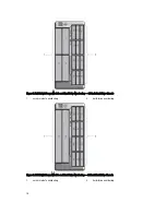
Page 151: ...Figure 94 System Board Connectors Back 1 midplane planar connectors 3 151 ...

Page 152: ...152 ...

Page 153: ...s type PCI Express Generation 2 Expansion slots Riser Slot 1 One standard height full length x8 link Slot 2 One standard height full length x8 link Slot 3 One standard height full length x8 link System board Slot 4 One low profile half length x8 link Slot 5 One low profile half length x8 link Slot 6 One low profile half length x8 link Slot 7 One low profile half length x8 link Slot 8 One low profi...

Page 154: ...tible Enclosure Control Panel Externally accessible connectors USB Two 4 pin USB 2 0 compliant connectors for keyboard and mouse support Video 15 pin VGA LCD panel features Four cursor control keys one select key LCD screen I O Module Specifications NOTE For more information on the technical specifications for the I O modules see the I O module documentation at dell com poweredgemanuals Environmen...

Page 155: ... 950 m 3 117 ft 35 C to 40 C 95 F to 104 F Maximum temperature is reduced by 1 C 175 m 1 F 319 ft above 950 m 3 117 ft 40 C to 45 C 104 F to 113 F Maximum temperature is reduced by 1 C 125 m 1 F 228 ft above 950 m 3 117 ft Particulate Contamination NOTE This section defines the limits to help avoid IT equipment damage and or failure from particulates and gaseous contamination If it is determined t...

Page 156: ...d in the System Event Log 10 of annual operating hours 5 C to 40 C at 5 to 85 RH with 26 C dew point NOTE Outside the standard operating temperature 10 C to 35 C the system can operate down to 5 C or up to 40 C for a maximum of 10 of its annual operating hours For temperatures between 35 C and 40 C de rate maximum allowable dry bulb temperature by 1 C per 175 m above 950 m 1 F per 319 ft 1 of annu...

Page 157: ...perature NOTE For more information on the server module specific restrictions for the expanded operating temperature range see the technical specifications in the server module Owner s Manual at dell com poweredgemanuals 157 ...

Page 158: ...158 ...

Page 159: ...ort page that lists the various support categories is displayed 4 For general support a Select your product category b Select your product segment c Select your product The support page that lists the various support categories is displayed Quick Resource Locator Use the Quick Resource Locator QRL to get immediate access to system information and how to videos This can be done by visiting dell com...

Reviews: