background image

Dell Vostro 5370

Owners's Manual

Regulatory Model: P87G
Regulatory Type: P87G001

Summary of Contents for Vostro 5370

Page 1: ...Dell Vostro 5370 Owners s Manual Regulatory Model P87G Regulatory Type P87G001 ...

Page 2: ...amage to hardware or loss of data and tells you how to avoid the problem WARNING A WARNING indicates a potential for property damage personal injury or death 2017 Dell Inc or its subsidiaries All rights reserved Dell EMC and other trademarks are trademarks of Dell Inc or its subsidiaries Other trademarks may be trademarks of their respective owners 2017 11 Rev A00 ...

Page 3: ...alling the coin cell battery 14 Solid State Drive optional 14 Removing the M 2 Solid State Drive SSD 14 Installing the M 2 Solid State Drive SSD 15 WLAN card 15 Removing the WLAN card 15 Installing the WLAN card 16 System fan 16 Removing the system fan 16 Installing the system fan 17 Heat sink 18 Removing the heat sink 18 Installing the heat sink 18 Input Output board 19 Removing the Input Output ...

Page 4: ...DC in 34 Palm rest 34 Removing and installing palmrest 34 eDP cable 35 Removing the eDP cable 36 Installing the eDP cable 36 Display back cover assembly 37 Removing the display back cover 37 Installing the display back cover 37 3 Technology and components 39 DDR4 39 DDR4 Details 39 Memory Errors 40 USB features 40 USB 3 0 USB 3 1 Gen 1 SuperSpeed USB 40 Speed 41 Applications 41 Compatibility 42 US...

Page 5: ...ptions 55 Performance 56 Power management 57 Post behavior 58 Virtualization support 59 Wireless options 59 Maintenance 60 System logs 60 SupportAssist system resolution 61 Updating the BIOS in Windows 61 Updating BIOS on systems with bitlocker enabled 62 Updating your system BIOS using a USB flash drive 62 Updating the Dell BIOS in Linux and Ubuntu environments 62 Flashing the BIOS from the F12 O...

Page 6: ...Software device drivers 71 Human Interface Device drivers 71 Firmware 71 Intel Dynamic Platform and Thermal Framework 72 7 Troubleshooting 73 Dell Enhanced Pre Boot System Assessment ePSA diagnostic 3 0 73 Running the ePSA diagnostics 73 Diagnostic LED 73 Battery status lights 74 8 Contacting Dell 75 6 Contents ...

Page 7: ...online or telephone service and support team Damage due to servicing that is not authorized by Dell is not covered by your warranty Read and follow the safety instructions that came with the product CAUTION To avoid electrostatic discharge ground yourself by using a wrist grounding strap or by periodically touching an unpainted metal surface at the same time as touching a connector on the back of ...

Page 8: ...mputer from the electrical outlet before performing Step 8 CAUTION To avoid electrostatic discharge ground yourself by using a wrist grounding strap or by periodically touching an unpainted metal surface at the same time as touching a connector on the back of the computer 8 Remove any installed ExpressCards or Smart Cards from the appropriate slots After working inside your computer After you comp...

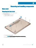
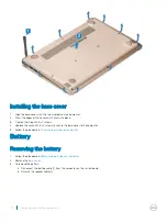
Page 9: ...inside your computer 2 To remove the base cover a Remove the seven M2 5 x 4 screws 1 b Loosen the three M2 5 x 7 screws 2 c Pry the base cover from the edge 1 NOTE You may need a plastic scribe to pry the base cover from the edge d Lift the base cover away from the system 2 2 Removing and installing components 9 ...

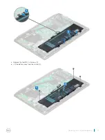
Page 10: ...ven M2 5 x 4 screws to secure the base cover to the computer 5 Follow the procedure in After working inside your computer Battery Removing the battery 1 Follow the procedure in Before working inside your computer 2 Remove the base cover 3 To remove the battery a Disconnect the battery cable 1 from the connector on the system board b Unroute the speaker cable 2 10 Removing and installing components...

Page 11: ...c Remove the four M2 0 x 3 screws 1 d Lift the battery away from the system 2 Removing and installing components 11 ...

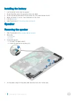
Page 12: ...secure the battery to the system 5 Install the base cover 6 Follow the procedure in After working inside your computer Speaker Removing the speaker 1 Follow the procedure in Before working inside your computer 2 Remove the a base cover b battery 3 To remove the speaker a Disconnect the speaker cable 1 b Unroute the cable from routing channel 2 4 Lift the speakers along with the speaker cable and r...

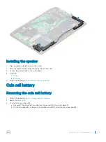
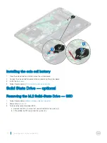
Page 13: ...e procedure in After working inside your computer Coin cell battery Removing the coin cell battery 1 Follow the procedure in Before working inside your computer 2 Remove the base cover 3 To remove the coin cell battery a Disconnect the coin cell battery cable from the connector on the system board 1 b Pry the coin cell battery to release from the adhesive and lift it away from the system board 2 R...

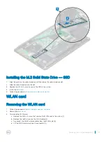
Page 14: ... Follow the procedure in After working inside your computer Solid State Drive optional Removing the M 2 Solid State Drive SSD 1 Follow the procedure in Before working inside your computer 2 Remove the base cover 3 To remove the solid state drive SSD a Remove the M2 0 x 3 screw that secure the SSD to the system 1 b Lift and slide the SSD away from the system 2 14 Removing and installing components ...

Page 15: ...llow the procedure in After working inside your computer WLAN card Removing the WLAN card 1 Follow the procedure in Before working inside your computer 2 Remove the base cover 3 To remove the WLAN card a Remove the M2 0 x 3 screw that secures the WLAN card to the system 1 b Remove the tab that secures the WLAN cables 2 c Disconnect the WLAN antenna cables from the WLAN card 3 d Lift the WLAN card ...

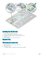
Page 16: ... 3 screw to secure it to the system 4 Install the base cover 5 Follow the procedure in After working inside your computer System fan Removing the system fan 1 Follow the procedure in Before working inside your computer 2 Remove the base cover 3 To remove the system fan a Disconnect the system fan cable from the connector on the system board 16 Removing and installing components ...

Page 17: ...e system fan to the system 1 c Lift the system fan away from the system 2 Installing the system fan 1 Place the system fan into the slot on the system 2 Replace the two M2 0 x 5 screws to secure it to the system Removing and installing components 17 ...

Page 18: ... To remove the heat sink a In sequential order as indicated on the heat sink loosen the four M2 0 x 4 screws that secure the heat sink to the system board 1 b Lift the heat sink away from the system 2 Installing the heat sink 1 Place the heat sink to its slot in the system 2 Tighten the four M2 0 x 4 screws to secure the heat sink to the system board 3 Install the a system fan b base cover 4 Follo...

Page 19: ...o remove the Input Output I O board a Remove the two M2 5 x 6 screws that secure the left display hinge to the system 1 b Lift the hinge 2 c Lift the latch and disconnect the I O cable from the connector on the I O board 3 4 d Remove the two M2 0 x 2 screws that secure the I O board to the system 1 e Lift the I O board away from the system Removing and installing components 19 ...

Page 20: ... with the two M2 5 x 6 screws to the system 5 Install the a WLAN b base cover 6 Follow the procedure in After working inside your computer Power button Removing the power button 1 Follow the procedure in Before working inside your computer 2 Remove the a base cover b WLAN card c solid state drive SSD d Input output I O board 3 To remove the power button a Remove the two M2 0 x 2 5 screws securing ...

Page 21: ...3 Install the a Input output I O board b WLAN c solid state drive SSD d base cover 4 Follow the procedure in After working inside your computer System board Removing the system board 1 Follow the procedure in Before working inside your computer 2 Remove the a base cover b battery c system fan d heat sink Removing and installing components 21 ...

Page 22: ...acklight cable 3 Keyboard and Touchpad cable 4 b Disconnect the eDP cable 1 power adapter port cable 2 and speaker cable 5 from the connector c Remove the two M2 0 x 5 screws that secure the USB Type C port bracket to the system board 3 d Lift the USB Type C port bracket away from the system 4 22 Removing and installing components ...

Page 23: ...e Remove the six M2 0 x 2 screws that secure the system board to the system 1 f Lift and remove the system board from the system 2 Removing and installing components 23 ...

Page 24: ... Connect the Input output board cable speaker cable keyboard backlight cable keyboard cable and touchpad cable to the system board 6 Install the a solid state drive SSD b heat sink c system fan d battery e base cover 7 Follow the procedure in After working inside your computer Touchpad Removing touchpad 1 Follow the procedure in Before working inside your computer 2 Remove the a base cover b batte...

Page 25: ...ce the four screws to secure the touchpad to the system 4 Paste the adhesive to the touchpad 5 Install the a battery b base cover 6 Follow the procedure in After working inside your computer Display assembly Removing display assembly 1 Follow the procedure in Before working inside your computer 2 Remove the a base cover b WLAN card 3 To remove the display assembly a Unroute the WLAN cable 1 and di...

Page 26: ...b Remove the four M2 5 x 4 screws 1 that secure the hinge bracket to the system and lift the display assembly c Lift and slide the display assembly 26 Removing and installing components ...

Page 27: ...display assembly Installing display assembly 1 Align and place the display assembly on the system 2 Place the hinge bracket on the system and replace the screws to secure the display assembly to the system Removing and installing components 27 ...

Page 28: ...uter Display bezel Removing display bezel 1 Follow the procedure in Before working inside your computer 2 Remove the a base cover b WLAN card c display assembly 3 To remove the display bezel a Using a plastic scribe pry the outer edges to release the display bezel from the display assembly 1 2 b Remove the display bezel from display assembly 28 Removing and installing components ...

Page 29: ... base cover 4 Follow the procedure in After working inside your computer Camera Removing the camera 1 Follow the procedure in Before working inside your computer 2 Remove the a base cover b WLAN card c display assembly d display bezel 3 To remove the camera a Slide the camera from the display assembly with a plastic scribe 1 b Disconnect the camera cable from the connector 2 c Lift the camera away...

Page 30: ...embly 3 Install the a display bezel b display assembly c WLAN card d base cover 4 Follow the procedure in After working inside your computer Display panel Removing display panel 1 Follow the procedure in Before working inside your computer 2 Remove the a base cover b WLAN card c display assembly d display bezel 30 Removing and installing components ...

Page 31: ...embly 1 and lift to turn over the display panel to access the eDP cable 2 b Remove the adhesive tape 1 c Lift the latch and disconnect the display cable from the connector on the display panel 2 d Lift the display panel 3 e The component you are left with is the display panel Removing and installing components 31 ...

Page 32: ...l b display assembly c WLAN card d base cover 6 Follow the procedure in After working inside your computer Display hinges Removing display hinge 1 Follow the procedure in Before working inside your computer 2 Remove the a base cover b WLAN card c display assembly d display bezel e display panel 3 To remove the display hinge a Remove the eight M2 5 x 4 screws that secure the display hinge to the di...

Page 33: ...w the procedure in After working inside your computer DC in Removing the DC in 1 Follow the procedure in Before working inside your computer 2 Remove the a base cover b WLAN card c display assembly 3 To remove the DC in a Remove the 3 M2 5 x 6 screws that secure the right display hinge bracket to the system 1 b Lift the hinge bracket 2 c Disconnect the power adapter port cable from the connector i...

Page 34: ...ard 3 Place the right display hinge and replace the 3 screws to secure the hinge to the system 4 Install the a display assembly b WLAN card c base cover 5 Follow the procedure in After working inside your computer Palm rest Removing and installing palmrest 1 Follow the procedure in Before working inside your computer 2 Remove the a base cover b battery 34 Removing and installing components ...

Page 35: ...s the component that you are left with is the palm rest 3 Install the following components on the new palm rest a display assembly b system board c powered button d Input Output I O board e WLAN card f solid state drive SSD g heat sink h system fan i touchpad j speaker k battery l base cover 4 Follow the procedure in After working inside your computer eDP cable Removing and installing components 3...

Page 36: ...the eDP cable 1 2 4 Peel the adhesive from the eDP cable connector and disconnect the cable from the display 3 Installing the eDP cable 1 Place the eDP cable on the display panel 2 Route the eDP cable through the routing channel 3 Connect the eDP cable to the connector and stick the adhesive 4 Install the a display hinge b display panel c camera d display bezel e display assembly f WLAN card 36 Re...

Page 37: ...WLAN card c display assembly d display bezel e camera f display panel g display hinge h eDP cable 3 The display back cover assembly is the remaining component after removing all the components Installing the display back cover 1 The display back cover assembly is the remaining component after removing all the components 2 Install the a eDP cable b display hinge c display panel d camera Removing an...

Page 38: ...e display bezel f display assembly g WLAN card h base cover 3 Follow the procedure in After working inside your computer 38 Removing and installing components ...

Page 39: ...olts of electrical power to operate DDR4 also supports a new deep power down mode that allows the host device to go into standby without needing to refresh its memory Deep power down mode is expected to reduce standby power consumption by 40 to 50 percent DDR4 Details There are subtle differences between DDR3 and DDR4 memory modules as listed below Key notch difference The key notch on a DDR4 modu...

Page 40: ...ters and peripheral devices like mice keyboards external drivers and printers Let s take a quick look on the USB evolution referencing to the table below Table 1 USB evolution Type Data Transfer Rate Category Introduction Year USB 3 0 USB 3 1 Gen 2 5 Gbps Super Speed 2010 USB 2 0 480 Mbps High Speed 2000 USB 3 0 USB 3 1 Gen 1 SuperSpeed USB For years the USB 2 0 has been firmly entrenched as the d...

Page 41: ...ifferential data USB 3 0 USB 3 1 Gen 1 adds four more for two pairs of differential signals receive and transmit for a combined total of eight connections in the connectors and cabling USB 3 0 USB 3 1 Gen 1 utilizes the bidirectional data interface rather than USB 2 0 s half duplex arrangement This gives a 10 fold increase in theoretical bandwidth With today s ever increasing demands placed on dat...

Page 42: ... Windows which continue to require separate drivers for USB 3 0 USB 3 1 Gen 1 controllers Microsoft announced that Windows 7 would have USB 3 1 Gen 1 support perhaps not on its immediate release but in a subsequent Service Pack or update It is not out of the question to think that following a successful release of USB 3 0 USB 3 1 Gen 1 support in Windows 7 SuperSpeed support would trickle down to ...

Page 43: ... or high definition video plus multichannel digital audio on a single cable NOTE The HDMI 1 4 will provide 5 1 channel audio support HDMI 1 4 Features HDMI Ethernet Channel Adds high speed networking to an HDMI link allowing users to take full advantage of their IP enabled devices without a separate Ethernet cable Audio Return Channel Allows an HDMI connected TV with a built in tuner to send audio...

Page 44: ...peed 2133 2400 MHz Connectors 2 Capacity 4 GB 8 GB 16 GB Minimum Memory 4 GB 1 x 4 GB Maximum memory 32 GB Video specification Feature Specification Video controller Intel Integrated UHD Graphics 620 8th Gen Core i5 i7 processors AMD Radeon 530 Graphics with 2GB 4GB GDDR5 vRAM Memory Shared system memory 2 GB 4 GB GDDR5 dedicated memory Audio specification Feature Specification Controller Realtek ...

Page 45: ...1 with Gen 1 Two one with PowerShare Video HDMI Memory card reader microSD card reader Display specification Feature Specification Type FHD 1920 x 1080 anti glare LED backlit display Size 13 3 inches Dimensions Height Width Diagonal 13 3 inches Active area X Y HD 1920 x 1080 Maximum resolution HD 1920 x 1080 Maximum Brightness 13 3 inch HD Anti Glare LCD display with LED backlight Operating angle ...

Page 46: ...h Configurable single finger and multi finger gestures Camera Feature Specification Camera type HD fixed focus Sensor type CMOS Sensor Still Resolution 1280 x 720 Pixels Maximum Video Resolution 1280 x 720 Pixels Maximum Diagonal 74 degrees Storage specification Features Specification Storage 128 GB M 2 SSD 256 GB M 2 SSD 512 GB M 2 SSD Battery specification Feature Specification Wattage 3 Cell 38...

Page 47: ...y 38 Whr Coin cell battery 3 V CR2032 lithium ion cell AC adapter Feature Specification Wattage 45 W and 65 W Input voltage 100 VAC to 240 VAC Input current maximum 1 3 A 1 7 A Input frequency 50 Hz to 60 Hz Output current continuous 2 31 A 3 34 A Rated output voltage 19 50 VDC Height 45 W 26 mm 1 02 inches 65 W 29 5 mm 1 16 inches Width 45 W 40 mm 1 57 inches 65 W 46 mm 1 81 inches Depth 45 W 94 ...

Page 48: ...on Temperature range Operating 10 C to 35 C 50 F to 95 F Storage 40 C to 65 C 40 F to 149 F Relative humidity maximum Storage 20 to 80 non condensing Maximum vibration Operating 5 to 350 Hz at 0 0002 G Hz Storage 5 to 500 Hz at 0 001 to 0 01 G Hz Maximum shock Operating 40 G 5 with pulse duration of 2 msec 10 equivalent to 51 cm sec 20 in sec Storage 105 G 5 with pulse duration of 2 msec 10 equiva...

Page 49: ...s for the system Diagnostics and BIOS Setup options are also included in this menu The devices listed on the boot menu depend on the bootable devices in the system This menu is useful when you are attempting to boot to a particular device or to bring up the diagnostics for the system Using the boot menu does not make any changes to the boot order stored in the BIOS The options are Legacy Boot Secu...

Page 50: ...y not appear General options Table 2 General Option Description System Information This section lists the primary hardware features of your computer The options are System Information Memory Configuration Processor Information Device Information Battery Information Displays the battery status and the type of AC adapter connected to the computer Boot Sequence Allows you to change the order in which...

Page 51: ...CI RAID On Default NOTE SATA is configured to support RAID mode Drives Allows you to enable or disable various drives on board The options are SATA 2 M 2 PCIe SSD 0 All the options are set by default SMART Reporting This field controls whether hard drive errors for integrated drives are reported during system startup This technology is part of the SMART Self Monitoring Analysis and Reporting Techn...

Page 52: ...he keyboard brightness level can be set from 0 to 100 The options are Disabled Dim Bright Default Keyboard Backlight Always on with AC Power The Keyboard Backlight with AC option does not affect the main keyboard illumination feature Keyboard Illumination will continue to support the various illumination levels This field has an effect when the backlight is enabled selected by default Keyboard Bac...

Page 53: ...ed to Not set Hence password has to be set for the first time you login and then you can change or delete the password The entries to set password are NOTE For the first time login Enter the old password field is marked to Not set Hence password has to be set for the first time you login and then you can change or delete the password M 2 SATA SSD Password Allows you to set change or delete the pas...

Page 54: ...eless Switch Changes This option is not set by default UEFI Capsule Firmware Updates Allows you to update the system BIOS via UEFI capsule update packages Enable UEFI Capsule Firmware Updates This option is set by default TPM 2 0 Security Allows you to enable or disable the Trusted Platform Module TPM during POST The options are TPM On Default Clear PPI Bypass for Enable Commands PPI Bypass for Di...

Page 55: ...n Secure Boot Enable Allows you to enable or disable the Secure Boot Feature Click one of the following options Disabled Default Enabled Expert Key Management Allows you to enable or disable Expert Key Management Enable Custom Mode This option is not set by default The Custom Mode Key Management options are PK Default KEK db dbx Intel Software Guard Extensions options Table 7 Intel Software Guard ...

Page 56: ...all cores enabled The performance of some applications improves with the additional cores All Default 1 2 3 Intel SpeedStep Allows you to enable or disable the Intel SpeedStep mode of processor Enable Intel SpeedStep This option is set by default C States Control Allows you to enable or disable the additional processor sleep states C states This option is set by default Hyper Thread Control Allows...

Page 57: ... option is not set by default USB Wake Support Allows you to enable USB devices to wake the system from standby Enable USB Wake Support This option is not set by default Peak shift This option minimizes AC power usage at times of peak demand Primary Battery Charge Configuration Allows you to select the charging mode for the battery The options are Adaptive Default Standard Fully charges your batte...

Page 58: ...owing options Minimal Thorough Default Auto Extended BIOS POST Time Allows you to create an additional preboot delay Click one of the following options 0 seconds Default 5 seconds 10 seconds Full Screen Logo Allows you to display full screen logo if your image matches screen resolution Enable Full Screen Logo This option is not set by default Sign of Life Indication Allows the system to indicate d...

Page 59: ...or VMM from utilizing the additional hardware capabilities provided by the Intel Virtualization technology for direct I O Enable VT for Direct I O This option is set by default Wireless options Table 12 Wireless Option Description Wireless Switch Allows to set the wireless devices that can be controlled by the wireless switch The options are WLAN WiGig Bluetooth All the options are enabled by defa...

Page 60: ... set by default Bios Recovery BIOS Recovery from Hard Drive This option is set by default Allows you to recover the corrupted BIOS from a recovery file on the HDD or an external USB key BIOS Auto Recovery Allows you to recover the BIOS automatically NOTE BIOS Recovery from Hard Drive field should be enabled Always Perform Integrity Check Performs integrity check on every boot System logs Table 14 ...

Page 61: ... Code and click Submit Click Detect Product and follow the instructions on screen 3 If you are unable to detect or find the Service Tag click Choose from all products 4 Choose the Products category from the list NOTE Choose the appropriate category to reach the product page 5 Select your computer model and the Product Support page of your computer appears 6 Click Get drivers and click Drivers and ...

Page 62: ...ase refer to the following article for further details http www dell com support article us en 19 SLN143196 how to create a bootable usb flash drive using dell diagnostic deployment package dddp lang EN 1 Download the BIOS update EXE file to another system 2 Copy the file e g O9010A12 EXE onto the bootable USB Flash drive 3 Insert the USB Flash drive into the system that requires the BIOS update 4...

Page 63: ... Updating from the One Time Boot Menu To update your BIOS from the F12 One Time boot menu you will need USB key formatted to the FAT32 file system key does not have to be bootable BIOS executable file that you downloaded from the Dell Support website and copied to the root of the USB key AC power adapter connected to the system Functional system battery to flash the BIOS Perform the following step...

Page 64: ...exe file is shown as an example in the following screenshot The actual file name may vary 5 Once the file is selected it will show in the file selection box and you can click the OK button to continue 64 System setup ...

Page 65: ...6 Click the Begin Flash Update button 7 A warning box is displayed asking you if you want to proceed Click the Yes button to begin the flash System setup 65 ...

Page 66: ...ould take as long as 10 minutes Generally this process takes two to three minutes 9 Once complete the system will reboot and the BIOS update process is completed System and setup password You can create a system password and a setup password to secure your computer Password type Description System password Password that you must enter to log on to your system Setup password Password that you must ...

Page 67: ...ck OK 4 Press Esc and a message prompts you to save the changes 5 Press Y to save the changes The computer reboots Deleting or changing an existing system and or setup password Ensure that the Password Status is Unlocked in the System Setup before attempting to delete or change the existing System and or Setup password You cannot delete or change an existing System or Setup password if the Passwor...

Page 68: ...64 bit Downloading drivers 1 Turn on the computer 2 Go to Dell com support 3 Click Product Support enter the Service Tag of your system and then click Submit NOTE If you do not have the Service Tag use the auto detect feature or manually browse for your system model 4 Click Drivers and Downloads 5 Select the operating system installed on your system 6 Scroll down the page and select the driver to ...

Page 69: ...Graphics controller driver Verify if the graphics controller driver is already installed in the computer Software 69 ...

Page 70: ...uter Network drivers The driver is labeled as Intel I219 LM Ethernet Driver Audio drivers Verify if the audio drivers are already installed in the computer Storage controller drivers Verify if the storage controller drivers are already installed in the computer 70 Software ...

Page 71: ... device drivers are already installed in the computer Software device drivers Verify if the software device drivers are already installed in the computer Human Interface Device drivers Verify if the human interface device drivers are already installed in the computer Firmware Verify if the Firmware drivers are already installed in the computer Software 71 ...

Page 72: ...Intel Dynamic Platform and Thermal Framework Verify if the Intel Dynamic Platform and Thermal Framework drivers are already installed in the computer 72 Software ...

Page 73: ...nd validation number and contact Dell Diagnostic LED This section details the diagnostic features of the battery LED in a notebook Instead of beep codes errors are indicated via the bicolor Battery Charge LED A specific blink pattern is followed by flashing a pattern of flashes in amber followed by white The pattern then repeats NOTE The diagnostic pattern will consist of a two digit number being ...

Page 74: ...found 3 4 BIOS recovery 2 recovery image found but invalid Battery status lights If the computer is connected to an electrical outlet the battery light operates as follows Alternately blinking amber light and white light An unauthenticated or unsupported non Dell AC adapter is attached to your laptop Alternately blinking amber light with steady white light Temporary battery failure with AC adapter...

Page 75: ... service options Availability varies by country and product and some services may not be available in your area To contact Dell for sales technical support or customer service issues 1 Go to Dell com support 2 Select your support category 3 Verify your country or region in the Choose a Country Region drop down list at the bottom of the page 4 Select the appropriate service or support link based on...

Reviews: