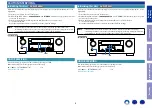

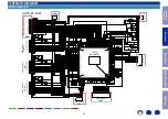
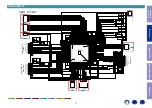
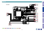

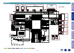

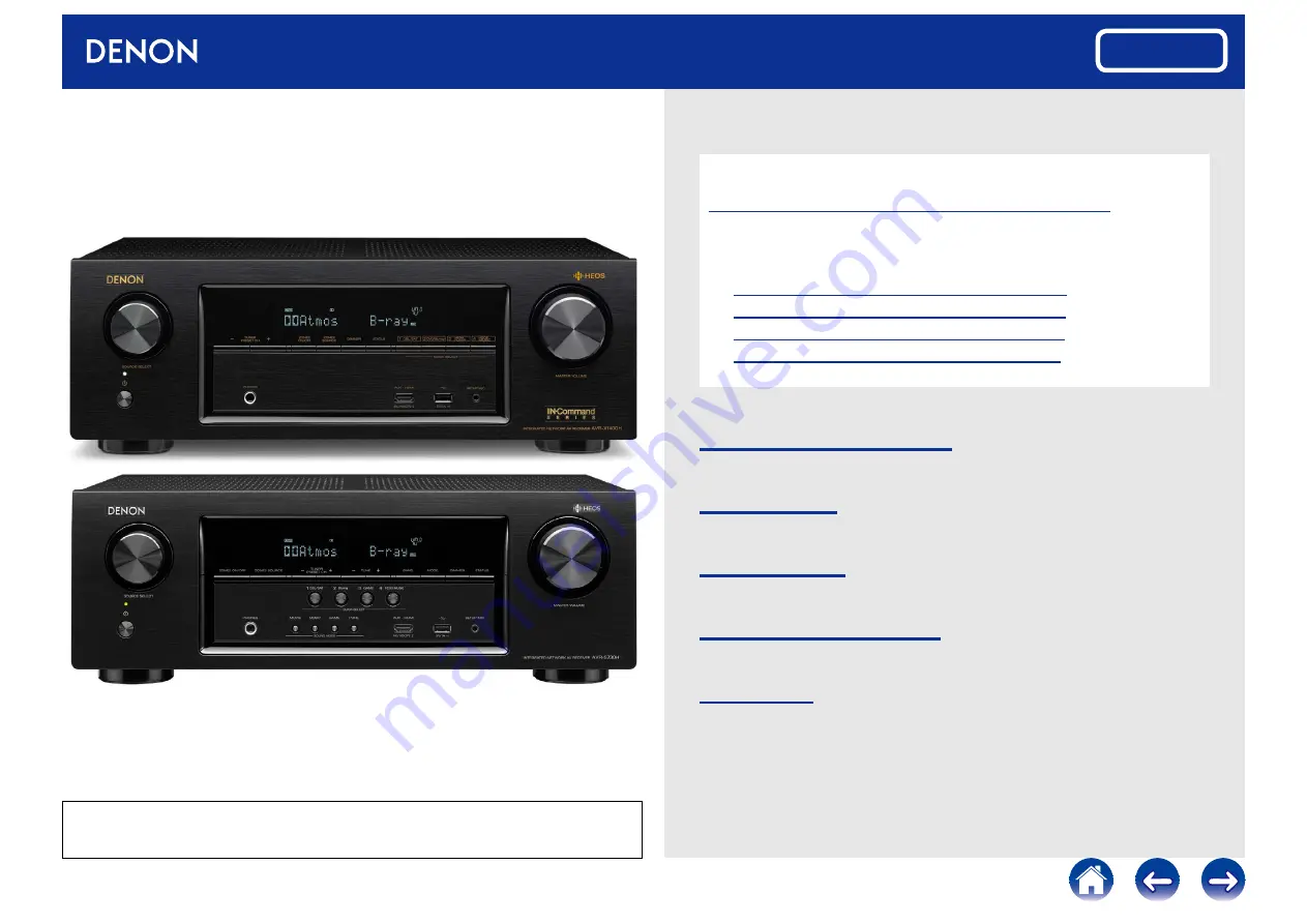
INTEGRATED NETWORK AV RECEIVER
AVR-X1400H
AVR-S730H
Service Manual
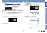
Click here!
On-line service parts list
URL:http://dmedia.dmglobal.com/Document/DocumentDetails/23150
Online Parts List
(P5 to P7)
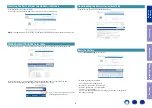
On-line owner’s manual
NA
: http://manuals.denon.com/AVRX1400H/NA/EN/index.php
EU:
http://manuals.denon.com/AVRX1400H/EU/EN/index.php
AP:
http://manuals.denon.com/AVRX1400H/AP/ZH/index.php
NA:
http://manuals.denon.com/AVRS730H/NA/EN/index.php
CAUTION IN SERVICING
ELECTRICAL
MECHANICAL
REPAIR INFORMATION
UPDATING
Ver. 2
Please refer to the MODIFICATION NOTICE.
purposes of improvement, specifications and design are subject to change without notice.
• Please use this service manual with referring to the operating instructions without fail.
• Some illustrations using in this service manual are slightly different from the actual set.
Summary of Contents for AVR-S730H
Page 148: ...www denon com ...