background image

Summary of Contents for AirWolf

Page 1: ......

Page 2: ...y start the vehicle if it is in GEAR Do not attempt to remotely start the vehicle if the ignition is on Do not remotely start the vehicle if it is indoors or in a poorly ventilated area Do not attempt to remotely start the vehicle if anyone is standing in front or behind of the vehicle Do not attempt remotely start the vehicle if anyone is inside of the vehicle Always apply the parking brake and p...

Page 3: ...control output connector CON 3 6 Valet switch CON 4 7 LED CON 5 8 Shock sensor CON 6 9 Trigger input connector CON 7 10 Programming the remote control 11 Programming for Tach Voltage Sense 12 Configuring Function timing 13 Configuration summary table 14 Antenna location 15 Relay diagram 5 6 8 10 14 18 18 18 19 23 24 26 30 30 31 ...

Page 4: ... circuits before making connections Always connect the ground wire CON 1 black before applying power to the unit The tach wire and the siren wire should never be grounded or come in contact with chassis ground in any way Always use fuses when using external relays Designtech International is not responsible for damages or injuries due to misuse or improper installation of the unit ...

Page 5: ...connected internally Switch One down hood open Switch one up hood closed Note that when switch one is down the remote may indicate the hood is open This unit is factory set for use with MANUAL TRANSMISSIONS If installing into a vehicle with an AUTOMATIC TRANSMISSION Cut the Manual Automatic RED LOOP DIP Switch Manual Automatic Loop DIP Switch OFF ON Normal Program DIP Switch Manual Automatic Red L...

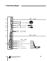
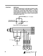
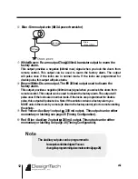
Page 6: ...6 v4 2 2 Overallwiringdiagram ...

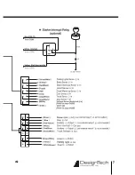
Page 7: ...7 v4 2 ...

Page 8: ...utput to power the additional wire s White ACC 12V output In most installations this wire will power the vehicle heater AC Connect this wire to the wire in the vehicle s ignition switch harness which shows 12 volts ONLY when the key is in the run position The correct wire will not have power with the key in the OFF ACC or CRANK positions If you have more than one wire which tests as described you ...

Page 9: ... bypass modules The ignition 3 output behaves exactly like ignition 1 except this output provides a ground while running Note As this output is connected internally to the ignition 1 relay a diode such as Radio Shacks 1n4001 not included may be needed to provide isolation if any feedback problems occur ...

Page 10: ... 300mA transistor Yellow Parking light output 10A relay Parking light output max of 10A Connect this wire to the parking light wire in the vehicle The correct wire in the vehicle will show 12 volts only when the parking lights are turned on When the parking lights are off the wire will show 0 volts NOTE In most cases connecting to one wire in the vehicle will illuminate all parking lights If not t...

Page 11: ...se is activated Refer to the following diagrams for proper connection White Starter Interrupt Signal output 300 mA transistor The 300mA output is used to disable starter via an external relay Green White type Starter Interrupt Relay Blue IGN 1 from CON1 Interrupt Start from module not included Green White type ...

Page 12: ...ck the doors from remote control This output can be used to disarm the factory alarm The output will pulse once if the locks are in normal mode If the locks are programmed for double pulse this output will pulse twice Note If the vehicle contains a factory alarm you MUST unlock the doors by remote to disarm the factory alarm prior to remote starting the vehicle Red Yellow Auxiliary 1 output 300 mA...

Page 13: ...om remote control This wire MUST be connected to a relay and MUST be configured EXACTLY as per the diagrams below If the door pin switches are not isolated from the Dome Light output it will cause the alarm to trigger and may cause the remote to incorrectly identify door status Brown Gray Black 3 type Brown Gray 4 type ...

Page 14: ...t is connected to a Type C configured as a Type A Damage will result Always use fuses when using external relays We suggest a maximum of 15A fuse Type A Positive This system supplies a 12V pulse from the factory switch to the factory relays IF you measure the resistance between the lock unlock wires and ground WITHOUT pressing the door lock switch the resistance should be more than 50 ohms If the ...

Page 15: ...orrect wires to fall to zero volts Connect the lock unlock wires from the unit to the described wires in the vehicle No additional parts should be required Type C Reverse Polarity Reverse Polarity In the vehicle the correct lock unlock wires will show continuity to ground less than 50 ohms when the lock unlock switch is not being pressed The same wires will show 12 volts when the lock unlock butto...

Page 16: ... lock button on the driver door is moved Central lock have no motor in the driver door Adding an actuator will work for central locking and vacuum type systems Vacuum lock systems are common in some European vehicles Type E Vacuum pump type Usually the door locks are locked and unlocked by using the key or plunger on a door often working only from the drivers door These types of systems are found ...

Page 17: ...17 v4 2 Type F One Wire System This system sends for unlock and becomes open for lock The system requires one external relay ...

Page 18: ...e proper connector on the main module 6 Valetswitch CON4 7 LED CON5 8 Shocksensor CON6 Mount the shock sensor to a solid structure underneath the dash Connect to the proper port on the unit Help reduce false alarms by adjusting the shock sensor so that a medium impact no damage to vehicle triggers the warning mode A severe impact damages vehicle should trigger the full alarm DO NOT test by hitting...

Page 19: ...Switch Input foot Brake Input Voltage sense IGN 1 Input see page 26 Trunk Input Glow Input Glow Input Parking light Input 9 2 Gray Black Door pin switch Input One of the door input wires MUST be installed to allow the unit to properly function including the programming and alarm functions If your vehicle uses a negative trigger door pin switch connect this wire to a wire in the vehicle which shows...

Page 20: ...e to a wire in the vehicle which shows 12 V when any door is open and 0V when all doors are closed NOTE If your vehicle uses a negative trigger door pin switch see 2 Gray Black Negative door pin switch wire The AirWolf system will not properly function without one of these door pin wires connected 9 4 Purple hood pin Switch Input This wire is used to detect opening of the hood via a pin switch tha...

Page 21: ...ack Glow Input optional This wire is used only in diesel applications to detect when the wait to start light has turned off Connect this wire to a wire in the vehicle which shows 0 volts when the glow plugs are on and 12 volts when the glow plugs are off In most vehicles this wire will be found in the instrument cluster If you wire in the vehicle shows 12 volts when the plugs are on and 0 when off...

Page 22: ...n the parking lights are left on If your vehicle has a positive parking light system connect this wire directly to the Yellow Parking Lights Wire from the remote start If your vehicle has a negative parking light system please refer to the diagram below Yellow White Parking light Input type F type ...

Page 23: ...n Step 1 Step 3 Step 2 Press and hold the buttons A and D at the same time for more than 2 seconds Adding Additional Handheld Remote Controls Up to 4 two way remote controls and 4 one way remote controls can be used with one vehicle Anytime within 5 minutes and before exiting the learning mode simply teach it another remote control Once you have completed the learning of all remote controls simply...

Page 24: ...ngine Start the warmed engine and open the door Step 1 Step2 Step 4 Step 3 Place the DIP switch at OFF position or close hood Because the measured value is saved in the permanent memory of the unit the tach is saved even if power is removed Note Return the DIP switch to OFF after programming Note door pin wire CON 7 must be connected and IGN 1 and ACC CON 1 must see 12 Volts For the above steps to...

Page 25: ... Alternatively you may open the hood if the hood pin switch is properly installed If you press and hold the Valet button for more than 4 seconds the car makes a tone and the function ends Step 2 Open the door Programming if connected in Voltage Sense mode If the Alternator Tachometer wire IS NOT connected to the tach wire as per PAGE 19 perform the steps below Do NOT use the Green Tach wire Connec...

Page 26: ...ntrol and the unit and is stored until the values are changed again Button A to transmit data after completing the configuration Button B and C to move menu or change the timing Button D to select menu or finish the timing configuration For data transmission after completing the configuration of the unit the ignition key should be in the on position and the hood and door should be open Timing Conf...

Page 27: ...e same time for more than 2 seconds Step 1 Step 2 Press the button A for transmission After completing the configuration press button D In LOCK status PressbuttonCfive timestomovetothe menu TRUNK is displayedonthe bottomoftheLCD Press button D to select Change the value using button B and C ...

Page 28: ...s to control an rear defrost windows sunroof neon etc Pulse mode will send a negative signal for the configured length of time while latched mode will provide a continuous output until the remote control button is pressed again 12 6 Trunk Controls the length of the trunk output pulse This is especially useful to control a device other than the factory trunk release 12 7 Alarm mode waiting time aft...

Page 29: ...consistently If the start overcranks reduce the time If the start does not crank long enough increase the time Adjustable from 0 1 to 1 second when it connected in TACH mode this setting controls the number of tach pulses the unit must see before releasing the starter A lower setting will fine tune the unit to disengage the start earlier while a higher value will cause the unit to crank the vehicl...

Page 30: ...econtrol Alternatorsetting TACHsetting Dip Switch 4 sec 4 sec 4 sec Door Open Engine running Brake Valetswitch Ignition On One chirp Valet ON 2 chirps Valet OFF Refer to the page 23 One chirp Switch OFF One chirp Transmission And Exit 4 chirps Error tone Action 3 inches 3 i n c h e s ...

Page 31: ...e current Note The colors of wires in the harness may be different from time to time The pin s always stay constant Supply and output to 85 and 86 polarity is not important and port 30 is transferred from 87A to 87 Using this schematic various applications circuits can be created Basic relay schematic The coil The contacts power supply Orange Ground ...

Page 32: ...32 v4 2 Example 1 To change the output to output Example 2 To change the output to output ...

Page 33: ...33 v4 2 MEMO ...

Page 34: ...34 v4 2 MEMO ...

Page 35: ...35 v4 2 MEMO ...

Page 36: ......

Reviews: