
QUICK INSTALLATION AND USER GUIDE V2.0
Full manual available on the unit's
web server
RTD-150T
Introduction
The
RTD-150T
is a 10" touch screen
repeater
.
When connected to an addressable panel, it
allows you to easily identify
events by displaying
them by type
, and to perform
actions
on the
panel, locate events on
maps
and send
informative
emails
.
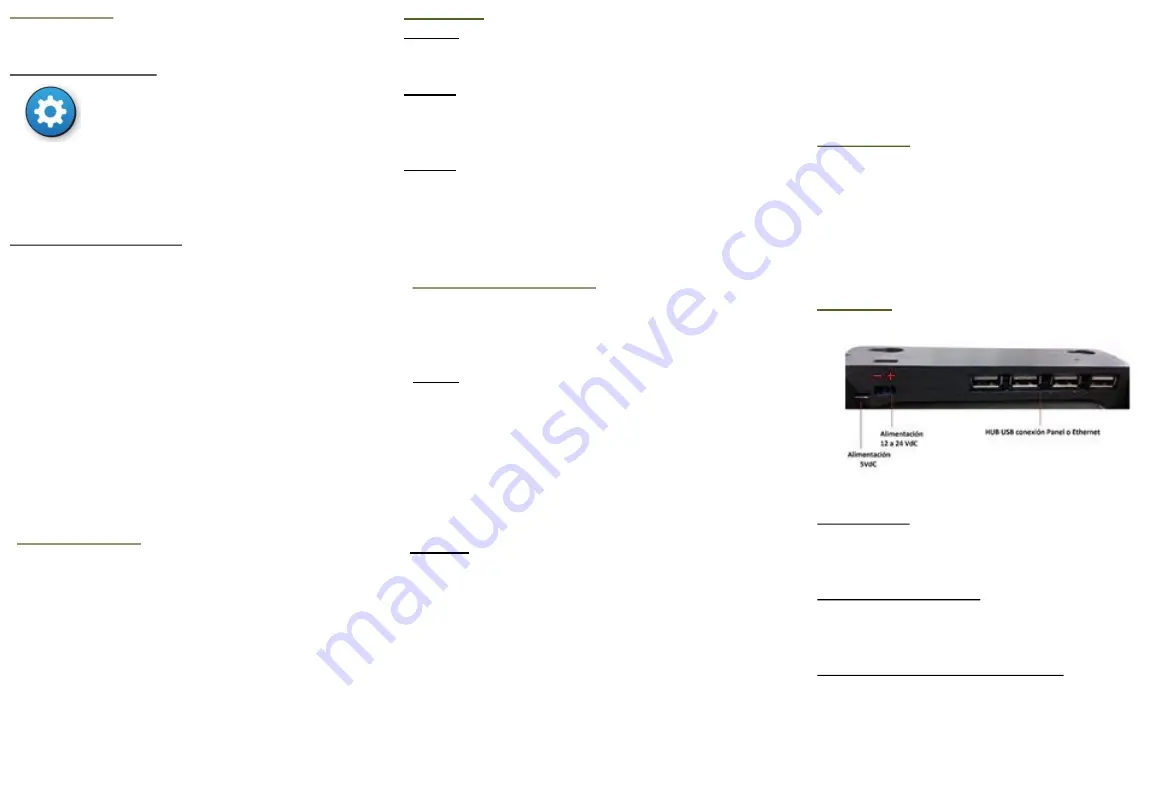
Hardware
Power supply:
Micro USB connector:
for 5 Vdc supply (inc)
Power strip:
for 12-24 Vdc power supply
Connection to the panel :
USB-RS-485 converter (inc)
: connect it to the unit's
USB hub and the panel's Modbus connection.
Connection to an IDR-
TS’s
IP network:
It is possible to create a network of RTD-150T and
RTD-150E repeaters.
Wi-Fi connection
802.11 b/g/n (inc)
Ethernet connection
through a
USB-RJ45
converter
(optional)
Configuration
The RTD-150T can be configured on the
touch screen
or
through its
web server.
1-On the touch screen:
+
password level 3
+
SYSTEM
tab
On the touch screen you configure the network options,
communication with the panel, the sound options,
emails, zone filters, etc. After changing the configuration,
press
“
Reboot
”
.
2-Through the web server:
Here you update the firmware and perform backups and
restores. To access it: using a browser on a computer that
is connected to the same network as the RTD-150T,
enter:
http://IP of unit
Ip of the unit:
By default, the RTD-150T is supplied with
the Wi-Fi connection enabled and the Ethernet disabled.
To connect the unit to a Wi-Fi network, on the
touch
screen
go to
SYSTEM
configuration and press the
CONFIGURACION
button.
In the WLAN section, select the network that you want to
connect the unit to and configure the password. Return
to the program, leave the configuration screen and then
re-enter. The unit will show the assigned IP.
Networked units
You can connect multiple repeaters in a single
installation. Each installation will always have a
master
unit and the rest will be
slaves
.
The
master
is the unit that will be connected to the
panel; you have to configure its connection parameters
with the panel. The other units will be
slaves
and you have
to configure the
master
unit's IP and port for them.
To
monitor
the connected units, they must
ALL
be
assigned a name under the
Repeater Name
option in the
SISTEMA (SYSTEM) tab in Configuration .
And on the master unit, you must enter the names
(separated by commas) under the option
List of names of
repeaters to be monitored
.
Areas, maps and devices
Maps are added by connecting a pen drive to one of
the unit's USB connectors. The pen drive will contain the
maps on its root directory. To add them on the
Zones/Maps
configuration tab, press
Upload maps
.
-Areas:
-
These are configured on the
screen Zones/Maps
tab.
-Areas can be associated with one of the panel's
zones
or they can be used to
connect maps
.
-To
locate the area
on a
map
, press
Define on map
and
mark the corner points of the sector that will form the
area. It is possible to draw more than one sector for an
area. To do this, press
New sector
.
-When you have finished, press
Save
.
-Devices:
-
These are configured on the
screen Devices
tab.
-For each device, configure the description, associated
area, type and model of device, the device's
Panel/Loop/Point and the icons associated with its
normal, alarm and fault statuses.
-You must also locate the device within the associated
map, by pressing
Place
. A sliding button allows you to
change the size of the device.
-When you have finished, press
Add
.
User levels
Level 1:
No password. Allows you to stop the RTD-
150E's warning sound by pressing the screen.
Level 2:
User password
1111
. Allows you to access the
alarm panel's actions menu:
Sounders On
,
Sounders
silence, Silenced buzzer and Reset
Level 3:
Installer password
2222
. Allows you to access
the unit's configuration.


