background image

2015-07-29

X40010 Rev. K

Caution: Do not tamper with 
the unit or its controls.
Call a qualified service 
technician.

Save these instructions for future reference.

Printed in Canada
Printed on 100% recycled paper

SIDEWALL VENTER

Models :

SMH-1-DE

SMH-6-DE

SMH-3-DE
SMH-4-DE
SMH-5-DE

SMH-1-BR
SMH-4-BR

Manufactured by:

DETTSON

Industries Dettson Inc.

Sherbrooke, Quebec

– Canada

www.dettson.ca

Summary of Contents for SMH-1-BR

Page 1: ...ied service technician Save these instructions for future reference Printed in Canada Printed on 100 recycled paper SIDEWALL VENTER Models SMH 1 DE SMH 6 DE SMH 3 DE SMH 4 DE SMH 5 DE SMH 1 BR SMH 4 B...

Page 2: ......

Page 3: ...reech of the heating unit and the power venter inlet This distance is the linear sum of all vertical and horizontal connecting pipes with a maximum of 4 90o elbows See Figure 1 Therefore the maximum e...

Page 4: ...ed between two buildings where their use is common to both buildings The vent terminal shall be installed such a way that the flue gases do not jeopardize people overheat combustible structures or ent...

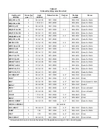
Page 5: ...1 50 SWV 2M 2S SMH 4 DE Beckett or Riello HMS 027 to 035 6 0 65 to 0 85 SWV 1M 2S SMH 1 DE Beckett or Riello HMS 041 to 062 6 1 00 to 1 50 SWV 2M 2S SMH 4 DE Beckett or Riello AMP 075 to 105 5 0 50 to...

Page 6: ...inside wall as closely as possible to the location where the vent pipe enters this wall Secure the junction box to the wall with two screws ensuring that the pressure switch is vertical If the wall i...

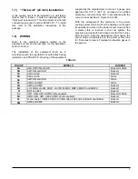
Page 7: ...specified in Figures 5A to 5M With this arrangement the command to the power venting system will come from the heating unit through its operational control to the power venter motor When a steady stat...

Page 8: ...st The installer must verify if the ignition of the burner is smooth when the heating unit operation is interrupted by means of the thermostat limit control or the power venter proving switch If the i...

Page 9: ...m the vent before operation To access the blower wheels remove the fan motor assembly cover and remove the blower wheels by unscrewing the attachment to the blower 3 1 3 Pressure switch The pressure s...

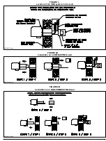
Page 10: ...DNS 0225 Rev A DNS 0226 Rev A FIGURE 1 SMH system General arrangement FIGURE 2 Main system dimensions...

Page 11: ...11 DNS 0229 Rev A DNS 0227 Rev A DNS 0228 Rev A FIGURE 3 Location of the SMH system on the wall Installation on a COMBUSTIBLE wall FIGURE 4A Installation on a NON COMBUSTIBLE wall FIGURE 4B...

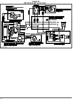
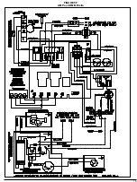
Page 12: ...12 DNS 0230 Rev C DNS 0397 Rev C FIGURE 5A AMI AMT IM and OLS 2 speeds Beckett or Riello AMT SM and OLS 2 speeds Beckett FIGURE 5B...

Page 13: ...13 DNS 0231 Rev C DNS 0232 Rev C FIGURE 5C AMI and HE 1 speed Beckett FIGURE 5D AMI and HE 1 speed Riello...

Page 14: ...14 DNS 0407 Rev C FIGURE 5E AMT SM and OSR 2 speeds Riello...

Page 15: ...15 FIGURE 5F AMP and OMB Riello...

Page 16: ...16 FIGURE 5G AMP and OMB Beckett DNS 0622 Rev A...

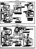
Page 17: ...17 FIGURE 5H FIGURE 5I DNS 0238 Rev B LO 1MQH LO 2M FBR 1 LO 1M3M MBP MBP F MBP 2 CCC and MBP U BRF and BFF DNS 0239 Rev B...

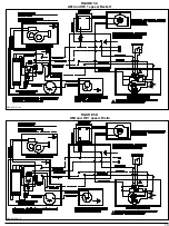
Page 18: ...18 FIGURE 5J FIGURE 5K DNS 0233 Rev D DNS 0234 Rev D FIGURE 5J HMT HML HMI and HMD with triple aquastat Beckett or Riello HMR HML HMT HMI and HMD with double aquastat Beckett...

Page 19: ...19 FIGURE 5L DNS 0235 Rev B DNS 0240 Rev C AME and HME Beckett FIGURE 5M Water heater CMO32 CMO50 30RB 32E2 50E2 IB 30 IB32 R and IB50 O Beckett...

Page 20: ...0 For SMH 4 SMH 5 and SMH 6 12 Cover support insulation B00733 13A Cover support B00705 For SMH 1 and SMH 3 13B Cover support B01074 For SMH 4 SMH 5 and SMH 6 14 Gasket outlet pipe B01150 Brown 1 15 G...

Reviews: