
IMPORTANT: Before using this equipment,
read all safety precautions and instructions.
Keep for future use.
DESCRIPTION
These pressure feed high volume low pres-
sure GTI
®
guns are designed to apply a wide
variety of finishing materials. These guns are
manufactured to provide maximum transfer
efficiency by limiting air cap pressure to 10
psi (complies with rules issued by SCAQMD
and other air quality authorities).
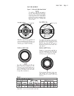
The GTI-520P (#2000 cap) gun will produce
approximately 10 psi cap pressure at 30 psi
gun inlet pressure. The GTI-546P (#46MP
cap) gun will produce approximately 10 psi
cap pressure at 50 psi gun inlet pressure.
Air cap test kits are available (see ACCES-
SORIES) which can be utilized to set the
exact air cap pressure. Air consumption
for the GTI-520P (#2000 cap) is 16.5 SCFM
at 10 psi air cap pressure. Air consumption
for the GTI-546P (#46MP cap) is 22.5 SCFM
at 10 psi air cap pressure.
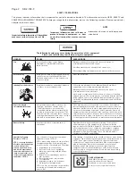
NOTE
These guns include 300 series
stainless steel fluid tips and
needles. Fluid passages are plated
brass and plated aluminum. Guns
may be used with chlorinated
solvent materials. See page 2 for
additional warnings.
Important: These guns may be used with
most common coating and finishing materi-
als. They are designed for use with mildly
corrosive and non-abrasive materials. If
used with other high corrosive or abrasive
materials, it must be expected that frequent
and thorough cleaning will be required and
the necessity for replacement of parts will
be increased.
INSTALLATION
For maximum transfer efficiency, do not use
more pressure than is necessary to atomize
the material being applied.
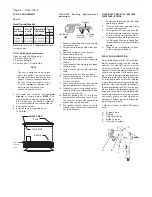
1. Connect the gun to a clean, moisture
and oil free air supply using a hose
size of at least 5/16" I.D. hose. Do not
use 1/4" I.D. hose (25' x 1/4" hose at 18
CFM has a pressure loss of 25 psi. 25'
x 5/16" hose at 18 CFM has a pressure
loss of 8 psi).
NOTE
Depending on hose length, larger
I.D. hose may be required. Install an
HAV-501 air gauge at the gun handle
and air cap test kit over tip. When
gun is triggered on, adjust regulated
SERVICE BULLETIN
SB-2-199-F
Replaces SB-2-199-E
Repair Kit KK-5058-2
GTI-520P and GTI-546P COMPLIANT PRESSURE FEED HVLP SPRAY GUNS
pressure to desired setting to provide
a maximum of 10 psi at the air cap.
Do not use more pressure than is
necessary to atomize the material
being applied. Excess pressure will
create additional overspray and
reduce transfer efficiency.
NOTE
If quick connects are required, use
only high flow quick connects ap-
proved for HVLP use such as DeV-
ilbiss HC-4419 and HC-4719. Other
types will not flow enough air for
proper gun operation.
NOTE
If an air adjusting valve is used at the
gun inlet, use DeVilbiss Model HAV-
500 or HAV-501. Some competitive
adjusting valves have significant
pressure drop that can adversely
affect spray performance. Models
HAV-500 and HAV-501 have minimal
pressure drop, which is important for
HVLP spraying.
2. Attach the fluid hose to the material
inlet.
NOTE
Protective coating and rust inhibi-
tors have been used to keep the
gun in good condition prior to
shipment. Before using the gun,
flush it with solvents so that these
materials will be removed from
fluid passages.
OPERATION
Mix, prepare and strain the material to be
sprayed according to the paint maufacturer's
instructions.
Strain material through a 60 or 90 mesh
screen.
1. Fill the pressure tank with the mate-
rial.
2. Open the spreader adjustment valve
(10) (Fan) by turning the valve stem
counterclockwise.
3. Open fluid adjusting screw (17) by
turning counterclockwise.
4.
Turn on air supply to gun and pressure
tank and set gun inlet pressure to low-
est recommended pressure for material
being sprayed. Spray a test area. Air
pressure and paint flow should be
adjusted to provide a uniform disper-
sion of atomized paint throughout the
pattern. Due to the unique cone shape
of the AV-2120 fluid tip, a slight back
pressure is created against the fluid
column. This will reduce the amount
of fluid output. To compensate, increase
the fluid regulator pressure slightly.
With 10 psi cap pressure, back pres-
sure is approximately 2.0 psi. Keep
air pressure as low as possible to
minimize bounce-back and overspray.
Excessive fluid flow will result in heavy
center spray patterns. Inadequate flows
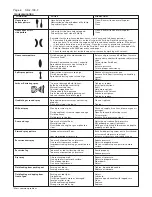
may cause the pattern to split. See
TROUBLESHOOTING, Page 5, if any
problems occur. If finer atomization is
required, increase gun inlet pressure.
If a reduced fluid flow rate is required,
turn fluid adjusting screw (17) clockwise
until desired fluid flow is obtained.
See Spray Gun Guide, SB-2-001 latest
revision, for details concerning setup of
spray guns.
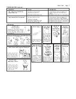
PREVENTIVE MAINTENANCE
To clean air cap and fluid tip, brush exterior
with a stiff bristle brush. If necessary to clean
cap holes, use a broom straw or toothpick
if possible. If a wire or hard instrument is
used, extreme care must be used to prevent
scratching or burring of the holes which will
cauase a distorted spray pattern.
To clean fluid passages, remove excess
material from cup, then flush with a suit-
able solvent. Wipe gun exterior with a
solvent dampened cloth. Never completely
immerse in solvent as this is detrimental to
the lubricants and packings.
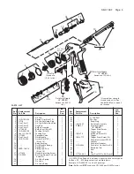
NOTE
When replacing the fluid tip or
fluid needle, replace both at the
same time. Using worn parts can
cause fluid leakage. See Chart 2.
Also, replace the needle packing
at this time. Lightly lubricate the
threads of the fluid tip before reas-
sembling. Torque to 15-20 ft. lbs.
Do not overtighten the fluid tip.
To prevent damage to fluid tip (5) or
fluid needle (11), be sure to either
1) pull the trigger and hold while
tightening or loosening the fluid
tip, or 2) remove fluid needle ad-
justing screw (17) to relieve spring
pressure against needle collar.


