background image

Grid-tied PV String Inverter

User Manual

R

Summary of Contents for SUN-10K-G

Page 1: ...Grid tied PV String Inverter User Manual R ...

Page 2: ...3 16 5 4 Max over current protection device 17 5 5 Inverter monitoring connection 17 5 6 Installation of Wi Fi Plug 5 7 Configuration of Wi Fi Plug 6 Startup and Shutdown 6 1 Start up the inverter 6 2 Inverter Shutdown 7 Zero export function Optional 7 1 Zero export function Optional 7 2 Sensor Clamp optional 7 3 Use of limiter function 18 18 19 19 19 20 20 22 23 7 4 Notes while using limiter func...

Page 3: ...o Use This Manual Read the manual and other related documents before performing any opera on on the inverter Documents must be stored carefully and be available at all mes Contents may be periodically updated or revised due to product development The informa on in this manual is subject to change without no ce The latest manual can be acquired via service deye com cn Single Phase String Power Inve...

Page 4: ...s steel screws M4 12 x4 Grid ed PV String Inverter x1 DC power connectors including Inserted spring x3 Stainless steel an collision bolt M6 80 x2 AC power connectors x1 User manual User manual x1 Square hole sealing plate For WIFI func on x1 Sensor Clamp op onal x1 Meter op onal x1 Datalogger op onal x1 DDSU666 DIN RAIL METER 230V 5 60 A 800imp kWh ...

Page 5: ...ruc ons which if not correctly followed could result in burns Safety Hint Note symbol indicates important safety instruc ons which if not correctly followed could result in some damage or the destruc on of the inverter Warning Warning symbol indicates important safety instruc ons which if not correctly followed could result in serious injury or death Shock Hazard Prohibit disassembling inverter ca...

Page 6: ... local power supply department the professionals can connect the inverter to the grid 5 Please take appropriate an sta c measure 6 Please install where children can not touch 7 When star ng the inverters first close the circuit breaker at the grid side then close the DC side when closing the inverters first disconnect the circuit breaker at the AC side then disconnect the DC side 8 Don t insert or r...

Page 7: ...lights in the front panel of the inverter Please see table 3 1 for details Explanation Inverter detects DC input Low DC input voltage Grid Connected Grid Unavailable Under normal opera ng Stop opera ng Detected faults or report faults Under normal opera ng Indicator status DC AC NORMAL ALARM on off on off on off on off Table 3 1 Status indicator lights ...

Page 8: ...lling through the displayed op ons the Up and Down keys Access to modify the adjustable se ngs the Esc and Enter keys The two line Liquid Crystal Display LCD is located on the front panel of the Inverter which shows the following informa on Inverter opera on status and data Service messages for operator Alarm messages and fault indica ons Esc Up Down Enter ...

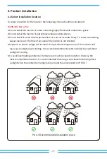
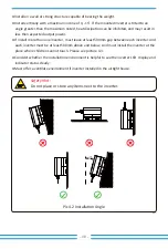
Page 9: ...reely To avoid overhea ng always make sure the flow of air around the inverter is not blocked Exposure to direct sunlight will increase the opera onal temperature of the inverter and may cause output power limi ng It is recommended that inverter installed to avoid direct sunlight or raining To avoid overhea ng ambient air temperature must be considered when choosing the inverter installa on loca on...

Page 10: ...ne inverter must leave at least 500mm gap between each inverter And each inverter must be at least 500mm above and below And must install the inverter at the place where children cannot touch Please see picture 4 3 Consider whether the installa on environment is helpful to see the inverter LCD display and indicator status clearly Must offer a ven late environment if inverter installed in the air gh...

Page 11: ...lla on The inverter is designed according to the wall mounted type installa on please use the wall mounted the brick wall of the expansion bolt when installing Pic 4 3 Installa on Gap Anchoring Moun ng bracket Stainless steel screws Inverter 500mm 500mm ...

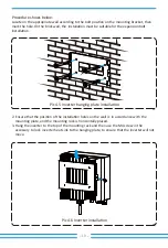
Page 12: ...en use the M4 screw in the accessory to lock inverter heat sink to the hanging plate to ensure that the inverter will not move Procedure shows below Locate on the appropriate wall according to the bolt posi on on the moun ng bracket then mark the hole On the brick wall the installa on must be suitable for the expansion bolt installa on Pic 4 5 Inverter hanging plate installa on Pic 4 6 Inverter in...

Page 13: ...se serious damages to the inverter Safety Hint Before connec ng inverter please make sure the PV array open circuit voltage is within the 550V of the inverter Safety Hint Before connec on please make sure the polarity of the output voltage of PV array matches the DC and DC symbols Safety Hint Please use approved DC cable for PV system Pic 5 1 DC connector MC4 Pic 5 2 DC connector MC4 Cable type Ra...

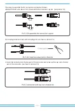
Page 14: ... 3 b Crimping metal terminals with crimping pliers as shown in picture 5 4 c Insert the contact pin to the top part of the connector and screw up the cap nut to the top part of the connector as shown in picture 5 5 Pic 5 3 Disassemble the connector cap nut 7mm 7mm Pic 5 4 Crimp the contact pin to the wire Pic 5 5 connector with cap nut screwed on ...

Page 15: ...arning Sunlight shines on the panel will generate voltage high voltage in series may cause danger to life Therefore before connec ng the DC input line the solar panel needs to be blocked by the opaque material and the DC switch should be OFF otherwise the high voltage of the inverter may lead to life threatening condi ons Warning Prohibit using a single circuit breaker for mul ple inverters prohib...

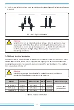
Page 16: ...tor body has two locking holes and press the locking valve in the hole inward to separate the matching socket from the sleeve Step 3 Use strippers to strip the protec ve sheath and insula on layer of the AC cable to the right length as shown in Picture 5 8 Step 4 Insert the cable L N PE into the sealing sleeve and sleeve Warning Be careful to dis nguish the L N and PE of the AC cables 1 Matching s...

Page 17: ...rn and insert each cable core into the corresponding jack and set each screw The connec on hole of AC connec on terminal labeling is shown in picture 5 9 Step 6 Set the sleeve and sealing ring in place Step 7 Connect the terminals to the inverter as shown in picture 5 10 Pic 5 9 AC Connector Hole Pa ern ...

Page 18: ...machine systems all PE cables of the inverter need to be connected to the same grounding copper platoon to ensure the equipoten al connec on The installa on of the shell ground wire is shown as picture 5 11 Warning Inverter has built in leakage current detec on circuit If an external leakage current protec on device is connected its opera ng current must be greater than 300 mA or higher otherwise ...

Page 19: ...8K G 230 32 6 34 8 50 SUN 10K G 230 43 5 60 Table 5 3 Recommended current protector specifica ons 5 5 Inverter monitoring connec on Pic 5 12 Internet monitoring solu on PC Web Server Smart Phone Router GPRS WIFI Inverter Inverter has the func on of wireless remote monitoring The inverter with Wi Fi func on is equipped with Wi Fi Plug to connect the inverter and network Wi Fi Plug s opera on install...

Page 20: ...the accessories and ghten the screws Insert the datalogger into the interface and fix it with a screw The configura on of the datalogger needs to be performed a er various electrical connec ons have been completed and the inverter DC power on When the inverter is on the DC power it is determined whether the datalogger is normally electrified The LED light shines out of the shell For the configura on o...

Page 21: ...hall not exceed the rated power of each channel Must follow below steps while shu ng down the inverter 1 Switch off the AC breaker 2 Wait for 30 seconds turn off the DC switch if any or simply disconnect the DC input connector The inverter will close the LCD and all indicators within two minutes When start up the single phase string inverter should fellow below steps 1 First switch on the AC breaker...

Page 22: ...tch we recommend to connect to the inverter output can refer to Table 7 2 If there is no integrated DC switch inside the inverter you purchased we commend you to connect the DC switch The voltage and current of the switch depend on the PV array you access DDSU666 DIN RAIL METER 230V 5 60 A 800imp kWh 2 5 6 1 4 7 8 3 Pulse Output RS 485 INPUT Pic 7 1 CHINT meter The string inverter supports zero ex...

Page 23: ...default password 1234 through pressing the bu on up down enter enter the opera on parameter se ng interface shown as picture 7 4 Warning Ensuring grid input cables connect 1 3 port of energy meter and inverter AC output cables connect 2 4 port of energy meter when connec ng 7 1 2 Use of zero export func on Pic 7 4 Meter switch Pic 7 3 Parameter se ng System Param Run Param Island OFF Meter OFF Pic...

Page 24: ...en the inverter outlet and the u lity grid the specs of the AC switch is determined according to the load capacity The AC switch we recommend to connect to the inverter output can refer to Table 5 1 If there is no integrated DC switch inside the inverter you purchased were commend you to connect the DC switch The voltage and current of the switch depends on the PV array you access 4 Operate the bu...

Page 25: ...n on the LCD panel in the main interface into the menu op ons select parameter se ng to enter setup submenu and then select running parameters as shown in picture 7 8 at this me please input the default password 1234 through pressing the bu on up down enter enter the opera on parameter se ng interface shown as picture 7 9 System Param Param 0FF Limiter Pic 7 9 Limit switch Pic 7 8 Parameter se ng ...

Page 26: ...d or current transformer arrow direc on is in wrong direc on Please read more on chapter 7 9 8 A er properly connec on is done wait for inverter star ng If the power of the PV array meets the current power consump on the inverter will maintain a certain output to counteract the power of the grid without backflow Safety Hint While the u lity power is nega ve and inverter has no output power that mea...

Page 27: ...nd the Down key to see the current DC voltage DC current AC voltage AC current inverter radiator temperature so ware version number and Wifi connec on state of the inverter Pic8 1 LCD opera on flow chart Start Devive Informa on Fault Record ON OFF Param Se ng System Param Run Param Protect Param Com Param PV VA LCD Main menu Time Meter ImpEp PV1 ExpEp LoadEp Load Grid and Fred U lity Power E Day and...

Page 28: ...5 2020 15 57 08 Pic 8 7 Meter power Meter Power 0W ImpEp Daily energy purchased from grid Total Total energy purchased from grid Pic 8 8 Electrical energy ImpEp 0 00KWh Total 0 00KWh ExpEp Daily energy sold to grid Total Total energy sold to grid Pic 8 9 Electrical energy ExpEp 0 00KWh Total 0 00KWh From the ini al interface you can check PV power PV voltage grid voltage inverter ID model and othe...

Page 29: ...Wh Total 0 00KWh E Day 0Wh E Total 134KWh Pic 8 13 Device informa on There are five submenus in the Main Menu 8 2 Submenus in the Main Menu 8 2 1 Device informa on Device Info Fault Record GL1030 SN 01 ID 0000000012 ID 0000000012 Ver0201 Ver1970 You can see the LCD so ware Ver0201 and Control So ware Version Ver1970 In this interface there are parameters such as rated power communica on addresses ...

Page 30: ...5 ON OFF se ng 8 2 3 ON OFF se ng 8 2 4 PV VA se ng ON OFF Setup Setup PV VA Turn ON Turn OFF Turn ON OK Cancel Turn OFF OK Cancel Branch 1 0 0A Branch 2 0 0A When the inverter is turned off it stops working immediately and go to standby mode and then will go to self test program again If it passed the self test it will start to work again Pic 8 16 PV String current Each PV string current and this ...

Page 31: ...et Pic 8 17 Submenus of the parameter setup 8 2 5 Parameter se ng 8 3 System param se ng Pic 8 18 System Param Pic 8 19 Time Setup PV VA System Param Run Param Protect Param Com Param 20200522 OK 08 11 21 Cancel Time Set Language Set Display Set Factory Reset Pic 8 20 Language Bright Keep Delay time 055 Delay time 055 OK Cancel Confirm Reset Cancel Pic 8 21 LCD Screen se ngs Pic 8 22 Delay me set ...

Page 32: ...ter s self check me The default value 60s Island An islanding protec on Meter Energy meter If inverter will connect meter then set here to ON Pic 8 25 8 4 1 Ac veP set ActiveP 0 ReactiveP 0 Island OFF Meter OFF PF 1 000 Fun ISO OFF Pic 8 26 Fun RCD OFF SelfCheck 0s Pic 8 27 Pic 8 28 Note Password required only for access authorized engineer Un authorized access may avoid the warranty The ini al pa...

Page 33: ...irements so customers don t need to reset it The password is same as 8 4 Running param WindTurbine when connec ng windturbine turn on this item Those parameters is used for setup wind trubine MPPT curve 8 5 Protect Param Pic 8 30 Pic 8 31 WindTurbine set WindTurbine OK Cancel V1 0 0V 0 0A DC1 Wind OFF DC2 Wind OFF OK Cancel Pic 8 32 Password MPPT Num 0 WindTurbine ...

Page 34: ...re not clear about it please consult your installer Note Engineer only Pic 8 33 CUSTOMIZED 00 INMETRO 00 EN50549 00 EN50438 00 IEC61727 00 CUSTOM OK Cancel AC OverVoltage 265 0V AC LowVoltage 185 0V AC OverFreq 51 50Hz AC LowFreq 47 50Hz Pic 8 34 Com Param 8 6 Com param set Address 16 BaudRate 9600 Address 16 BaudRate 9600 ...

Page 35: ... high and the touch can cause burns Turn off the inverter and wait for it cooling then you can clean and maintain Warning No solvent abrasive materials or corrosive materials can be used for cleaning any parts of the inverter Error code Description Ongrid Single Phase F01 DC input polarity reverse fault Check the PV in put polarity F03 DC leakage current fault Hardly appear the code Never ever happ...

Page 36: ...t the inverter if the error s ll exists please contact your installer or Deye service Three phase current over current fault F22 Contact your installer for help Crash stop if there is a stop bu on F19 1 When inverter is running wifi plug plugin will occur F19 2 Restart the inverter or factory reset if the error s ll exists please contact your installer or Deye service All hardware failure synthesis...

Page 37: ...t the inverter if the error s ll exists please contact your installer or Deye service Three phase current over current fault F22 Contact your installer for help Crash stop if there is a stop bu on F19 1 When inverter is running wifi plug plugin will occur F19 2 Restart the inverter or factory reset if the error s ll exists please contact your installer or Deye service All hardware failure synthesis...

Page 38: ... 1 It tells the PV input voltage is low and it always happens in the early morning 2 Check PV voltage and Ubus voltage When inverter is running then showing F56 maybe Loss of driver or need update firmware 3 Restart the inverter if the fault s ll exists contact your installer or Deye service F57 AC reverse irriga on AC reverse irriga on F58 AC grid U over current Hardly appear the code Never ever h...

Page 39: ...rrent A Max AC Output Current A Output Power Factor 0 5 47 52 or 57 62 op onal 97 7 97 5 120 550 100 550 12 5 25 2 1 2 12 5 25 2 1 2 25 25 2 2 2 230 180 300 this may vary with grid standards 50 60 Op onal Single phase SUN 7 5K G 9 8 7 5 8 3 32 6 35 9 0 8 leading 0 8 lagging 2 SUN 10K G 13 10 11 43 5 47 8 SUN 8K G 10 4 8 8 8 34 8 38 3 Grid Current THD 330 310 198 5 Transformerless Size mm W H D 11 ...

Page 40: ...Add No 26 30 South Yongjiang Road Beilun 315806 Ningbo China Fax 86 0 574 8622 8852 Tel 86 0 574 8622 8957 E mail service deye com cn Web www deyeinverter com 502012003 Ver 2 0 2020 11 ...

Reviews: