

1
ES121-LR
Installation Guide
Package Contents
1 x ES121 system unit
1 x Quick Installation Guide
1 x CD disk includes:
-
Drivers
-
Manual
1 x 60W power adaptor
Optional Items
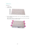
1 x VESA mount kit
- 1 VESA bracket
- 6 bracket screws
1 x Wallmount kit
- 2 wallmount brackets
- 4 bracket screws
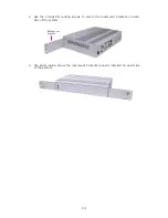
1 x Rackmount kit
- 2 L-shape rackmount brackets with handle
- 8 bracket screws
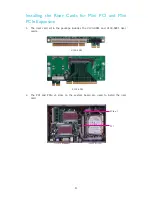
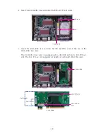
1 Riser card kit (X100-4PE1 + X100-5PE1)
- Equipped with a Mini PCI slot and a Mini PCIe x1 slot
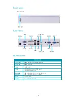
System Models
CPU
Intel
®
Atom
TM
D510
Intel
®
Atom
TM
D410
Intel
®
Atom
TM
N450
Model
ES121-LRD510
ES121-LRD410
ES121-LRN450


