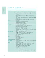
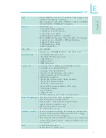
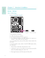
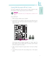
background image

935-UX5831-000G

08300848E

System Board
User’s Manual

Summary of Contents for LANPARTY UT X58 t3eh8

Page 1: ...935 UX5831 000G 08300848E System Board User s Manual ...

Page 2: ... Class B This equipment has been tested and found to comply with the limits for a Class B digital device pursuant to Part 15 of the FCC rules These limits are designed to provide reasonable protection against harmful interference when the equip ment is operated in a residential installation This equipment generates uses and can radiate radio frequency energy and if not installed and used in accord...

Page 3: ...l Warranty Static Electricity Precaution Safety Measures About the Package Before Using the System Board System Board Layout English Français Deutsch Italiano Español Debug LED POST and Troubleshooting 4 4 5 5 6 6 7 8 38 70 102 137 168 ...

Page 4: ...oduct inability to use the product unauthorized replacement or alteration of components and product specifica tions 2 The warranty is void if the product has been subjected to physi cal abuse improper installation modification accidents or unau thorized repair of the product 3 Unless otherwise instructed in this user s manual the user may not under any circumstances attempt to perform service adju...

Page 5: ...r ends Important Electrostatic discharge ESD can damage your processor disk drive and other components Perform the upgrade instruction procedures described at an ESD workstation only If such a station is not available you can provide some ESD protection by wearing an antistatic wrist strap and attaching it to a metal part of the system chassis If a wrist strap is unavailable estab lish and maintai...

Page 6: ... accessories in the package may not come similar to the information listed above This may differ in accordance to the sales region or models in which it was sold For more infor mation about the standard package in your region please contact your dealer or sales representative Before Using the System Board Before using the system board prepare basic system components If you are installing the syste...

Page 7: ... 1 13 ATX power 1 IDE 1 1 Intel X58 Battery JMicron JMB363 LGA 1366 USB 2 3 Clear CMOS J P2 Intel ICH10R 1 1 1 1 Speaker On Off J P8 Safe boot J P1 Secondary RTC Reset J P12 PCIE1 PCIE3 PCIE4 1 1 DIMM 1 DIMM 2 DIMM 4 DIMM 3 DIMM 6 DIMM 5 Fan 3 SPI Flash BIOS PS 2 power select J P7 DRAM Power LED USB 6 11 select JP5 power Marvell 88E8052 Marvell 88E8053 PCI 1 JP26 JP27 1 CPU FSB select JP13 JP15 5V...

Page 8: ...240 pin DDR3 DIMM sockets DDR3 800 1066 1333 1600 O C MHz DIMMs Triple channel memory architecture Supports up to 24GB system memory Delivers up to 43 2GB s bandwidth Unbuffered x8 x16 non ECC and ECC up to 4Gb DDR3 devices 3 PCI Express Gen 2 x16 slots a 2 way CrossFire at x16 x16 transfer rate lanes or b 3 way SLI at x16 x8 x8 transfer rate lanes 1 PCI Express x4 slot 2 PCI slots Award BIOS 8Mbi...

Page 9: ...dditional external USB 2 0 ports 1 connector for an external COM port 1 connector for an IEEE 1394 port 1 connector for the Bernstein audio module 1 IrDA connector and 1 CIR connector 8 Serial ATA connectors 1 40 pin IDE connector and 1 floppy connector 1 24 pin ATX power connector 1 8 pin 12V power connector 2 4 pin 5V 12V power connectors FDD type 1 front panel connector 6 fan connectors 1 diagn...

Page 10: ...boot up problems you can reconfigure the system with the default values stored in the ROM BIOS To load the default values stored in the ROM BIOS please follow the steps below 1 Power off the system then unplug the power cord 2 Set JP2 pins 2 and 3 to On Wait for a few seconds and set JP2 back to its default setting pins 1 and 2 On 3 Now plug the power cord then power on the system Clear CMOS Data ...

Page 11: ... 1 Make sure the standby power is present 2 Using the EZ touch switches on the system board first press the Reset button then the Power button simultaneously for approxi mately 4 seconds If the system board is already enclosed in a chassis apply the same method using the Reset button and Power button located at the front panel of the chassis 3 After 4 seconds release the power button first then th...

Page 12: ...3 1 2 3 1 2 USB Power Select X USB 6 11 JP5 X USB 0 5 JP6 2 3 On 5VSB 1 2 On 5V default 1 3 2 1 3 2 2 3 On 5VSB 1 2 On 5V default Selecting 5VSB will allow you to use the USB keyboard or USB mouse to wake up the system Important The 5VSB power source of your power supply must support 720mA Important The 5VSB power source of your power supply must support 1 5A 2 devices or 2A 3 or more devices 3 1 ...

Page 13: ...as the PC s speaker By default the buzzer is on allowing you to hear the system s beep messages and warnings If you intend to use an exter nal speaker turn this function off by setting JP8 pins 1 and 2 to On Speaker On Off Select JP8 2 3 On Speaker On default 1 2 On Speaker Off Buzzer 3 1 2 3 1 2 X ...

Page 14: ... system 1 Power off the system then unplug the power cord 2 Set pins 2 and 3 to On Wait for a few seconds then set the jumper back to its default setting pins 1 and 2 On 3 Plug the power cord then power on the system The system will reboot normally without losing all data stored in the CMOS Safe Boot 1 2 On Default 3 1 2 3 1 2 X JP1 2 3 On Safe boot ...

Page 15: ...sets the manageability register bits in the RTC Note 1 The SRTCRST input must always be high when all other RTC power planes are on 2 In the case where the RTC battery is dead or missing on the platform the SRTCRST pin must rise before the RSMRST pin 3 1 2 3 1 2 X JP12 2 3 On RTC reset 1 2 On Normal default ...

Page 16: ... 2 On This setting will allow the system to automatically run according to the CPU s FSB If you want to change the setting please refer to the table below JP15 JP14 JP13 By CPU 1 2 On 1 2 On 1 2 On FSB 800 3 4 On 2 3 On 2 3 On FSB 1066 2 3 On 2 3 On 2 3 On FSB 1333 2 3 On 2 3 On 3 4 On JP15 1 3 2 JP14 JP13 ...

Page 17: ...el ICH9R 1 1 1 CPU_VTT Select X 3 1 2 3 1 2 3 1 2 3 1 2 1 2 On 2 3 On 1 2 On 2 3 On JP26 JP27 CPU_VTT 1 2V default 1 4V 1 6V JP26 1 2 On 2 3 On 2 3 On JP27 1 2 On 2 3 On 1 2 On JP26 and JP27 are used to select the CPU s voltage ...

Page 18: ...r storage peripherals The 10 pin connector allows you to connect an additional 1394 port Your 1394 port may come mounted on a card edge bracket Install the card edge bracket to an available slot PS 2 Ports and IEEE 1394 Ports W 1394 0 W PS 2 Mouse PS 2 KB Rear Panel I O Ports USB 8 9 USB 10 11 USB 6 7 1394 1 W 12V fused 1 TPA Ground TPB 12V fused Key TPA Ground TPB Ground 2 10 9 PS 2 Mouse 1394 0 ...

Page 19: ... connect 6 additional USB 2 0 1 1 ports Your USB ports may come mounted on a card edge bracket Install the card edge bracket to an available slot at the rear of the system chassis then connect the USB port cables to these connectors LAN Ports The LAN ports allow the system board to connect to a local area network by means of a network hub W W W USB 11 USB 10 USB 7 USB 6 USB 9 USB 8 1 VCC Data Data...

Page 20: ...nter and subwoofer speakers of the audio system Rear Right Left Jack Black This jack is used to connect to the rear right and rear left speakers of the audio system Side Right Left Jack Gray This jack is used to connect to the side left and side right speakers of the audio system Line in Line out Mic in Center Subwoofer Rear R L Side R L S PDIF in S PDIF out Side view 1 5 5V Key SPDIF out GND SPDI...

Page 21: ...t are at the front panel of your system Optical S PDIF Connector The optical S PDIF connector is used to connect an external audio output device using an optical S PDIF cable Important DO NOT use optical S PDIF and coaxial RCA S PDIF at the same time Installing the Bernstein Audio Module 1 The Bernstein audio module connects to the system board by means of the provided audio cable 2 Insert one end...

Page 22: ... expansion bracket slot then secure the module by replacing the bracket screw you removed earlier Audio cable Serial ATA Connectors The Serial ATA SATA connectors are used to connect Serial ATA drives Connect one end of the Serial ATA cable to a Serial ATA connector and the other end to your Serial ATA device ICH10R supports SATA 1 to SATA 6 JMB363 supports SATA 7 and SATA 8 Configuring RAID Refer...

Page 23: ...or The IDE disk drive connector is used to connect 2 IDE disk drives An IDE cable have 3 connectors on them one that plugs into this connector and the other 2 connects to IDE devices The connector at the end of the cable is for the Master drive and the connector in the middle of the cable is for the Slave drive The colored edge of the cable should align with pin 1 of this connector Note When using...

Page 24: ...your operating system to use the IrDA CIR function Refer to your operating system s manual or documentation for more information Serial COM Connector The serial COM connector is used to connect modems serial print ers remote display terminals or other serial devices Your COM port may come mounted on a card edge bracket Install the card edge bracket to an available slot at the rear of the system ch...

Page 25: ...ing fans will provide adequate airflow throughout the chassis to prevent over heating the CPU and system board components X X CPU fan 2nd fan System fan X NB fan 1st fan 1 3 Ground Power N C X X X Sense Power Ground Speed Control 1 4 1 3 Ground Power N C 1 3 Ground Power N C Fan 3 3 1 Ground Power N C 3 1 Ground Power N C ...

Page 26: ...ence of the power switch and reset switch on the system board are user friendly especially to DIY users They provide conven ience in powering on and or resetting the system while fine tuning the system board before it is installed into the system chassis X Reset Power ...

Page 27: ...ver you power on the system POST will detect the status of the system and its components Each code displayed on the LED corresponds to a certain system status Warning When the DRAM Power LED and or Standby Power LED lit red it indicates that power is present on the DIMM sockets and or PCI slots Power off the PC then unplug the power cord prior to installing any memory modules or add in cards Failu...

Page 28: ...d into this connector Your power supply unit may come with an 8 pin or 4 pin 12V power connector The 12V power enables the delivery of more 12VDC current to the processor s Voltage Regulator Module VRM If available it is preferable to use the 8 pin power otherwise connect a 4 pin power to this connector X X 13 1 12 24 3 3VDC 3 3VDC COM 5VDC COM 5VDC COM PWR_OK 5VSB 12VDC 12VDC 3 3VDC 3 3VDC 12VDC ...

Page 29: ...d in cards peripherals etc may exceed the minimum power requirement To ensure that adequate power is provided we strongly recommend that you use a minimum of 400 Watt or greater power supply Important Insufficient power supplied to the system may result in instabil ity or the add in boards and peripherals not functioning prop erly Calculating the system s approximate power usage is im portant to e...

Page 30: ...em s configuration such as the wattage of the power supply the se quence of the supplied power as well as the number of periph eral devices connected to the system Due to this reason we strongly recommend that you wait for the Standby Power LED refer to the LEDs section in this chapter for the location of the Standby Power LED to lit off 2 After the Standby Power LED has lit off wait for 6 seconds...

Page 31: ...tem SPEAKER Speaker Connector This connects to the speaker installed in the system chassis ATX SW ATX Power Switch Depending on the setting in the BIOS setup this switch is a dual function power button that will allow your system to enter the Soft Off or Suspend mode PWR LED Power Standby LED When the system s power is on this LED will light When the system is in the S1 POS Power On Suspend or S3 ...

Page 32: ...N C PWRBT PWRBT N C N C Ground H W Reset Speaker Data N C Ground Speaker Power LED Power LED Power LED Power or Standby Signal Download Flash BIOS Connector 1 GROUND 2 8 7 SPI_VCC3 SPI_CS0B SPI_MIS0 SPI_HOLD SPI_CLK SPI_MOSI Note If a system did not boot up and the Power Standby LED did not light after it was powered on it may indicate that the CPU or memory module was not installed properly Pleas...

Page 33: ...e slot then press it down firmly until it is completely seated in the slot The retaining clip of the slot will automatically hold the graphics card in place PCI Express x4 Install PCI Express cards such as network cards or other cards that comply to the PCI Express specifications into the PCI Express x4 slot PCIE 2 2 way CrossFire 3 way SLI PCIE 1 x16 x16 PCI Express Slots Configuration PCIE 3 N C...

Page 34: ...l front panel cables from the chassis to the front panel smart connector Connect according to the pin definition shown on the smart connector Front Panel Connectors USB 1394 Front Panel 2 Connect the front panel smart connector to the front panel connector on the system board USB and IEEE 1394 Connectors 1 Connect your USB 1394 port cable to the USB 1394 smart connector Connect according to the pi...

Page 35: ...AID 1 Mirroring Disk Array with Fault Tolerance RAID 1 copies and maintains an identical image of the data from one drive to the other drive If a drive fails to function the disk array management software directs all applications to the other drive since it contains a complete copy of the drive s data This enhances data protection and increases fault tolerance to the entire system Use two new driv...

Page 36: ...l ruin the entire installation process and operating system The system will not boot and you will lost all data in the hard drives Please give special attention to this warning because there is no way of recovering back the data Step 2 Configure Serial ATA in the Award BIOS 1 Power on the system then press Del to enter the main menu of the Award BIOS 2 Configure Serial ATA in the appropriate field...

Page 37: ...y SCSI or RAID driver message 3 Press S to Specify Additional Device 4 At this point you will be prompted to insert a floppy disk containing the RAID driver Insert the provided RAID driver diskette 5 Locate for the drive where you inserted the diskette then select RAID or AHCI controller that corresponds to your BIOS setup Press Enter to confirm You have successfully installed the driver However y...

Page 38: ... d accès mémoire d Intel Pont sud Intel ICH10R Autobus de système 4 8GT s 6 4GT s Six interfaces de connexion DDR3 DIMM à 240 broches DDR3 800 1066 1333 1600 O C MHz DIMMs Architecture mémoire à triple voies Prend en charge jusqu à 24 Go de mémoire système Délivre jusqu à 43 2 Go s de bande passante Dispositifs sans mémoire tampon x8 x16 avec ou sans ECC jusqu à 4 Go de DDR3 3 PCI Express Gen 2 x1...

Page 39: ...cteur pour 1 série 1 connecteur pour module audio Bernstein 1 connecteur IR et 1 connecteur CIR 8 connecteurs Serial ATA 1 connecteur IDE et 1 connecteur de FDD 1 connecteur d alimentation 24 pin ATX 1 connecteur d alimentation 8 pin 12V ATX 2 prises d alimentation 4 broches 5V 12V type FDD 1 connecteur devant panneau 6 connecteurs de ventilateurs et 1 indicateur diagnostiques EZ interrupteurs bou...

Page 40: ...igurer le système aux valeurs par défaut stockées dans la ROM BIOS Pour charger les valeurs par défaut dans la ROM BIOS veuillez suivre les étapes ci dessous 1 Débrancher le système et retirer le cordon d alimentation 2 Mettre les broches du JP2 2 et 3 sur ON Attendre quelques secondes et remettre JP2 par défaut broches 1 et 2 On 3 Rebrancher maintenant le cordon d alimentation et allumer le systè...

Page 41: ...le soit présente 2 En utilisant les commutateurs à touche EZ de la carte système appuyer d abord sur le bouton réinitialisation et ensuite simultanément sur le bouton d alimentation pendant environ 4 secondes Si la carte système est déjà mise dans le châssis appliquer la même méthode en utilisant le bouton de réinitialisation et le bou ton d alimentation situés sur le panneau frontal du châssis 3 ...

Page 42: ...lavier USB ou la souris USB pour réveiller le système Important The 5VSB power source of your power supply must support 1 5A 2 devices or 2A 3 or more devices Important La source d alimentation 5VSB de votre alimentation doit supportée 720mA 1 Intel ICH9R 1 1 1 X JP7 2 3 On 5VSB 1 2 On 5V default 3 1 2 3 1 2 1 Intel ICH9R 1 1 1 X USB 6 11 JP5 X USB 0 5 JP6 2 3 On 5VSB 1 2 On 5V default 1 3 2 1 3 2...

Page 43: ...vertisseur sonore est ON permettant d entendre les bips des messages et les avertissements Si vous voulez utiliser un haut parleur externe éteindre cette fonction en réglant les broches 1 et 2 du JP8 sur On Sélection des Haut parleurs ON OFF 1 Intel ICH9R 1 1 1 JP8 2 3 On Speaker On default 1 2 On Speaker Off Buzzer 3 1 2 3 1 2 X ...

Page 44: ...retirer le cordon d alimentation 2 Mettre les broches du JP1 2 et 3 sur ON Attendre quelques secondes et remettre JP1 par défaut broches 1 et 2 On 3 Rebrancher maintenant le cordon d alimentation et allumer le système Le système redémarrera normalement sans perte des données stockées dans le CMOS Amorce Sécurisée 1 Intel ICH9R 1 1 1 1 2 On Default 3 1 2 3 1 2 X JP1 2 3 On Safe boot ...

Page 45: ...octets du registre de l horloge Note 1 L entrée SRTCRST doit toujours être élevée lorsque toutes les autres couches Power plane de l horloge sont ON 2 Dans le cas où la pile de l horloge soit inopérante ou manquante sur la plateporme la broche SRTCRST doit être montée avant la broche RSMRST 1 Intel ICH9R 1 1 1 3 1 2 3 1 2 X JP12 2 3 On RTC reset 1 2 On Normal default ...

Page 46: ...ner automatiquement en fonction du FSB du processeur Si vous désirez modifier le réglage veuillez vous référer au tableau ci dessous Sélectionner le FSB du Processeur 4 1 Intel ICH9R 1 1 1 X JP15 1 3 2 JP14 JP13 JP15 JP14 JP13 By CPU 1 2 On 1 2 On 1 2 On FSB 800 3 4 On 2 3 On 2 3 On FSB 1066 2 3 On 2 3 On 2 3 On FSB 1333 2 3 On 2 3 On 3 4 On ...

Page 47: ...rançais Français 1 Intel ICH9R 1 1 1 Sélectionner le CPU_VTT X 3 1 2 3 1 2 3 1 2 3 1 2 1 2 On 2 3 On 1 2 On 2 3 On JP26 JP27 CPU_VTT 1 2V default 1 4V 1 6V JP26 1 2 On 2 3 On 2 3 On JP27 1 2 On 2 3 On 1 2 On ...

Page 48: ...riphériques de stockage Le raccord 10 broches permet de vous connecter à un appareil 1394 supplémentaire Votre port 1394 peut être livré monté sur un support encartable Installer Ports PS 2 et IEEE 1394 1 Intel ICH9R 1 1 1 W 1394 0 W PS 2 Mouse PS 2 KB 1394 1 W 12V fused 1 TPA Ground TPB 12V fused Key TPA Ground TPB Ground 2 10 9 Ports I O de l arrière du Panneau USB 8 9 USB 10 11 USB 6 7 PS 2 Mou...

Page 49: ...nte disponible à l arrière du châssis du système et raccorder les câbles des ports USB à ces connecteurs Ports LAN Les ports LAN permettent à la carte système de se connecter à un réseau local au moyen d un concentrateur réseau 1 Intel ICH9R 1 1 1 LAN 1 LAN 2 W W W USB 11 USB 10 USB 7 USB 6 USB 9 USB 8 1 VCC Data Data GND Key VCC Data Data GND N C 2 10 9 USB 4 5 USB 2 3 USB 0 1 le support encartab...

Page 50: ...ise de caisson de basse central orange Cette prise est utilisée pour se connecter aux haut parleurs de basse et centraux du système audio Prise arrière gauche droite noire Cette prise est utilisée pour se connecter aux haut parleurs arrière droits et gauches du système audio Line in Line out Mic in Center Subwoofer Rear R L Side R L S PDIF in S PDIF out Side view 1 5 5V Key SPDIF out GND SPDIF in ...

Page 51: ...ecevoir les signaux audio d un lecteur CD ROM d une carte TV ou MPEG Connecteur audio frontal Le connecteur audio frontal est utilisé pour raccorder les prises micro d entrée et les sorties de ligne line out sur le panneau frontal de votre système Connecteur optique S PDIF Le connecteur optique S PDIF est utilisé pour raccorder un appareil de sortie audio externe en utilisant un câble optique S PD...

Page 52: ...le audio et retirer le support Mettre le module audio Bernstein dans la fente du suppor t d extension et fixer le module en remettant la vis de support que vous avez retirée à l étape 3 2 Insérer une extrémité du câble sur le connecteur Audio Bernstein sur la carte système et l autre sur le connecteur correspondant sur le module audio Connecteur de module Audio Bernstein 1 Intel ICH9R 1 1 1 X Bern...

Page 53: ... connecteur en série ATA et l autre extrémité sur votre appareil en série ATA ICH10R supporte SATA 1 à SATA 6 JMB363 supporte SATA 7 et SATA 8 Configuration du Système RAID Se référer au chapitre RAID de ce manuel pour obtenir davantage d informations sur la création d un système RAID sur les disques durs en série ATA Connecteurs I O 1 Intel ICH9R 1 1 1 SATA 1 2 SATA 7 8 SATA 5 6 SATA 3 4 ...

Page 54: ... est utilisé pour raccorder 2 disques IDE Il possède un mécanisme d insertion qui empêche la mauvaise installation du cable IDE Un câble IDE comporte 3 connecteurs un qui se branche sur ce connecteur et les deux autres qui se connectent sur les appareils IDE Le connecteur à l extrémité du câble est pour le disque maître et celui au milieu du câble est pour l esclave Le bord coloré du câble devrait...

Page 55: ...urs broches Il se peut que vous deviez installer les disques dans votre système d exploitation convenants à l utilisation de la fonctionnalité IrDA CIR Se référer au manuel de votre système d exploitation ou à la docu mentation pour obtenir davantage d informations Connecteur en Série COM Le connecteur en série COM est utilisé pour raccorder les mo dems les imprimantes en série les terminaux d aff...

Page 56: ...dissement Ces connecteurs de ventilateur sont utilisés pour raccorder les ventilateurs de refroidissement Les ventilateurs de refroidissement fournissent une ventilation adéquate à l intérieur du châssis afin d empêcher toute surchauffe du processeur et des composants de la carte système 1 Intel ICH9R 1 1 1 X X CPU fan 2nd fan System fan X NB fan 1st fan 1 3 Ground Power N C X X X Sense Power Grou...

Page 57: ...r les utilisateurs étant bricoleurs Ils sont très pratiques pour allumer ou réinitialiser le système tout en ajustant la carte système avant l installation sur le châssis Commutateurs à Touche EZ Commutateur Download Flash BIOS 1 Intel ICH9R 1 1 1 X Reset Power 1 Intel ICH9R 1 1 1 1 GROUND 2 8 7 SPI_VCC3 SPI_CS0B SPI_MIS0 SPI_HOLD SPI_CLK SPI_MOSI X ...

Page 58: ...est allumé POST détectera le statut du système et de ses composants Chaque code affiché sur le voyant DEL correspond à un certains statut du système Avertissement Lorsque le voyant DEL d alimentation DRAM et ou d alimentation à l état de veille sont rouge cela indique que le courant passe dans les supports DIMM et ou dans les fentes PCI Eteindre le PC et débrancher le cordon d alimentation avant d...

Page 59: ...ut être livrée avec un connecteur d alimentation 12V à 4 ou 8 broches L alimentation 12V permet la fourniture de courant 12VDC en direction du module de régulation de tension du processeur VRM Voltage Regulator Mod ule Si disponible il est préférable d utiliser une alimentation 8 broches sinon raccorder une alimentation 4 broches à ce connecteur 1 Intel ICH9R 1 1 1 X 13 1 12 24 3 3VDC 3 3VDC COM 5...

Page 60: ...nt pour garantir que l alimentation soit suffisante pour la consommation du système Les connecteurs d alimentation de l unité d alimentation électrique sont conçus pour s adapter aux connecteurs à 24 et 8 broches seulement dans une direction S assurer d observer la bonne orienta tion avant de brancher les connecteurs Les connecteurs d alimentation de type FDD sont des connecteurs supplémentaires d...

Page 61: ...la configuration du système telle que le nombre de Watt de l alimentation de la séquence de l alimentation ainsi que du nombre d appareils périphériques reliés au système Pour ces raisons nous conseillons fortement d attendre que le voyant DEL de veille se référer à la section voyants DEL de ce chapitre pour la localisation de ce voyant s éteigne 2 Une fois le voyant DEL de veille éteint attendre ...

Page 62: ... par conséquent en permettant une durée de vie de l alimentation ou du système prolongée SPEAKER Connecteur du Haut parleur Il se connecte au haut parleur installé dans le châssis du système ATX SW Commutateur d alimentation ATX Dépendant des réglages à l intérieur du BIOS ce commutateur est un bouton d alimentation à deux fonctions qui permettra à votre système d entrer en mode Soft Off ou Suspen...

Page 63: ...pas allumé après le démarrage cela peut indiquer que le processeur ou le module n ont pas été installés correctement Veuillez vous assurer qu ils soient correctement insérés dans leur support Pin 3 5 14 16 8 10 18 20 7 9 13 15 17 19 2 4 6 HD LED Primary Secondary IDE LED Reserved ATX SW ATX power switch Reserved RESET Reset switch SPEAKER Speaker connector PWR LED Power Standby LED Pin Assignment ...

Page 64: ...jusqu à ce qu elle rentre complètement dans la fente Le clip de maintien de la fente maintiendra automatiquement la carte graphique en place PCI Express x4 Installer les cartes PCI Express telles que les cartes de réseau ou autres cartes se conformant avec les spécifications PCI Express dans la fente PCI Express x4 Configuration des Fentes PCI Express 1 Intel ICH9R 1 1 1 PCIE 1 PCIE 2 PCIE 4 PCIE ...

Page 65: ...nneau avant du châssis au connecteur Smart du panneau avant Raccordez en fonction de la définition de la broche indiquée sur le connecteur Smart Connecteurs du Panneau Avant USB 1394 Connecteurs du Panneau Avant 2 Raccordez le connecteur Smart du panneau avant au connecteur du panneau avant de la carte système Connecteurs USB et IEEE 1394 1 Raccordez votre câble du port USB 1394 au connecteur Smar...

Page 66: ...faillant résultera en une perte des données dans la matrice RAID 1 matrice de disque à écriture mirroir à tolérance d erreur RAID 1 copie et conserve une image identique des données d un disque à l autre Si un disque fonctionne incorrectement le logiciel de gestion de la matrice envoie toutes les applications en direction de l autre disque puisqu il contient une copie complète des données du disqu...

Page 67: ...cipal du BIOS 2 Configurer le disque ATA en série dans les champs appropriés 3 Appuyer sur Esc pour retourner au menu principal de l utilitaire d installation du BIOS Sélectionner Save Exit Setup et appuyer ensuite sur Enter 4 Taper Y et appuyer sur Enter 5 Redémarrer le système Etape 1 Raccorder les disques durs en série ATA RAID 5 RAID 5 répartit en écriture les données et les informations conce...

Page 68: ...installé lors de l installation de Windows XP ou de Windows 2000 en utilisant la méthode d installation F6 Ceci est nécessaire afin d installer le SE sur un disque dur ou sur un volume RAID lors du mode RAID ou sur un disque dur lors du mode AHCI 1 Lancer l installation de Windows en démarrant depuis le CD d installation 2 Appuyer sur F6 lors de la demande dans la ligne de statut en utilisant la t...

Page 69: ...e fois les fichiers copiés lors de l installation de Windows retirer la disquette afin de laisser l ordinateur redémarrer après l installation de Windows Etape 5 Installer le Intel Matrix Storage Manager Etape 6 Installer le driver de JMB36X Se référer à la version complète du manuel pour les étapes d installation du progiciel et du pilote Veuillez télécharger le manuel depuis le site Web de DFI w...

Page 70: ...600 O C MHz DIMMs 3 Kanal Speicher Architektur Unterstützung für bis zu 24GB Systemspeicher Bietet bis zu 43 2GB s Bandbreite Ungepufferte x8 x16 nicht ECC und ECC bis zu 4Gb DDR3 3 PCI Express Gen 2 x16 Steckplätze a 2 Way CrossFire Lanes mit x16 x16 Übertragungsrate oder b 3 way SLI Lanes mit x16 x8 x8 Übertragungsrate 1 PCI Express x4 Einbauplätzen 2 PCI Einbauplätzen Kompatibilität mit Award B...

Page 71: ...nittstelle 1 CIR Schnittstelle 8 Serial ATA Anschlüsse 1 40 polige IDE Anschlüsse 1 Floppy Anschlüsse 1 24 polige Anschlußstecker für das ATX Netzgerät 1 8 polige 12V Anschlußstecker für das ATX Netzgerät 2 4 polige 5V 12V Netzstecker für FDD 1 Vorderseite Füllung Anschlüsse 6 ventilator Anschlüsse 1 diagnostischen Außenindikatoren EZ Umschaltern der Knopf der Speisung und des Auslasses ACPI und O...

Page 72: ... das System mit den im ROM BIOS gespeicherten Standardwerten rekonfigurieren Um die im ROM BIOS gespeicherten Standardwerte zu laden führen Sie bitte die folgenden Schritte aus 1 Schalten Sie das System aus und ziehen Sie den Netzstecker 2 Setzen Sie die JP2 Pins 2 und 3 auf On Warten Sie nun einige Sekunden und setzen Sie dann die JP2 Pins zurück in die Ausgangsposition Pins 1 und 2 On Löschen de...

Page 73: ...wendung von EZ Clear 1 Stellen Sie sicher dass das System auf Standby steht 2 Betätigen Sie die EZ touch Schalter auf dem Systemboard zuerst den Reset Schalter und anschliessend gleichzeitig den Power Schalter für ca 4 Sekunden Sollte das Systemboard bereits in ein Gehäuse eingebaut sein so wenden Sie die gleiche Methode mit den Reset und Power Schaltern an der Frontseite des Gehäuses an 3 Nach de...

Page 74: ...Power Wählen Sie Die Auswahl von 5VSB erlaubt es Ihnen Ihr System per USB Key board oder USB Maus aufzuwecken Wichtig Die 5VSB Stromquelle Ihres Netzteils muss 1 5V 2 ports oder 2V 3 oder mehr Ports Vunterstützen 1 Intel ICH9R 1 1 1 X JP7 2 3 On 5VSB 1 2 On 5V default 3 1 2 3 1 2 1 Intel ICH9R 1 1 1 X USB 6 11 JP5 X USB 0 5 JP6 2 3 On 5VSB 1 2 On 5V default 1 3 2 1 3 2 2 3 On 5VSB 1 2 On 5V defaul...

Page 75: ...deinstellung des Summers on wodurch Sie die Warnungen und Piep Nachrichten des Systems hören Falls Sie externe Lautsprecher verwenden wollen so schalten Sie diese Funktion durch das Setzen der JP8 Pins 1 und 2 auf On aus Speaker On Off Auswahl 1 Intel ICH9R 1 1 1 JP8 2 3 On Speaker On default 1 2 On Speaker Off Buzzer 3 1 2 3 1 2 X ...

Page 76: ...r 2 Setzen Sie die JP1 Pins 2 und 3 auf On Warten Sie nun einige Sekunden und setzen Sie dann die Pins zurück in die Ausgangsposition JP1 Pins 1 und 2 On 3 Verbinden Sie nun wieder den Netzstecker und schalten Sie das System ein Das System wird neu starten normalerweise ohne Verlust aller in CMOS gespeicherten Daten Zulässiger Start 1 Intel ICH9R 1 1 1 1 2 On Default 3 1 2 3 1 2 X JP1 2 3 On Safe ...

Page 77: ...it der Registerbits der RTC zurück Hinweis 1 Der SRTCRST Input muss immer hoch sein wenn alle anderen RTC Versorgungslagen laufen 2 In dem Fall dass die RTC Batterie leer ist oder ganz fehlt muss der SRTCRST Pin vor dem RSMRST Pin stehen 1 Intel ICH9R 1 1 1 3 1 2 3 1 2 X JP12 2 3 On RTC reset 1 2 On Normal default ...

Page 78: ... entsprechend dem Frontside Bus der CPU Falls Sie die Einstellungen ändern wollen finden Sie Informationen in der folgenden Tabelle CPU FSB wählen Sie JP15 JP14 JP13 By CPU 1 2 On 1 2 On 1 2 On FSB 800 3 4 On 2 3 On 2 3 On FSB 1066 2 3 On 2 3 On 2 3 On FSB 1333 2 3 On 2 3 On 3 4 On 4 1 Intel ICH9R 1 1 1 X JP15 1 3 2 JP14 JP13 ...

Page 79: ... 9 Deutsch Deutsch 1 Intel ICH9R 1 1 1 CPU_VTT wählen Sie X 3 1 2 3 1 2 3 1 2 3 1 2 1 2 On 2 3 On 1 2 On 2 3 On JP26 JP27 CPU_VTT 1 2V default 1 4V 1 6V JP26 1 2 On 2 3 On 2 3 On JP27 1 2 On 2 3 On 1 2 On ...

Page 80: ... IEEE 1394 Ports Der IEEE 1394 0 Port dient dem Anschluss von Audio Video Geräten oder externen Massenspeichern Der 10 Pin Anschluss erlaubt Ihnen die Verbindung mit einem zusätzlichen 1394 Gerät Ihr 1394 Port könnte auf einem Halterungsblech befestigt sein PS 2 Ports und IEEE 1394 Ports 1 Intel ICH9R 1 1 1 W 1394 0 W PS 2 Mouse PS 2 KB 1394 1 W 12V fused 1 TPA Ground TPB 12V fused Key TPA Ground ...

Page 81: ... verbinden Sie das Kabel des USB Ports mit dem entsprechenden Anschluss LAN Ports Über die LAN Ports können Sie das Systemboard über einen Netzwerk Hub mit einem lokalen Netzwerk verbinden USB Ports und LAN Ports 1 Intel ICH9R 1 1 1 LAN 1 LAN 2 W W W USB 11 USB 10 USB 7 USB 6 USB 9 USB 8 1 VCC Data Data GND Key VCC Data Data GND N C 2 10 9 USB 4 5 USB 2 3 USB 0 1 Installieren Sie das Blech in eine...

Page 82: ...Line in Stecker Hellblau Mit diesem Stecker verbinden Sie beliebige Audiogeräte wie z B Stereoanlagen CD Player Kassettenrecorder AM FM Radios Synthe sizer etc mit dem System Line out Stecker Hellgrün Mit diesem Stecker verbinden Sie die vorne links und vorne rechts Lautsprecher Ihres Audiosystems mit dem System Line in Line out Mic in Center Subwoofer Rear R L Side R L S PDIF in S PDIF out Side v...

Page 83: ... Tuner oder MPEG Karte zu empfangen Front Audio Anschluss Mit dem Front Audio Anschluss werden die line out und mic in Stecker die sich an der Frontseite des Gehäuses befinden verbunden Optischer S PDIF Anschluss Mit dem optischen S PDIF Anschluss werden externe Audioausgabegeräte die optische S PDIF Kabel verwenden verbunden Wichtig Verwenden Sie NICHT optische S PDIF und koaxiale RCA S PDIF glei...

Page 84: ...o module connector 3 Die Länge des Audiokabels bietet Ihnen die Option und Flexibilität das Modul in jede beliebige Halterung auf der Rückseite des Gehäuses einzusetzen Lösen Sie die Schraube der Halterung die Sie für das Audiomodul vorgesehen haben und entfernen Sie das Blech Setzen Sie das Bernstein Au dio Module in die Halterung ein und sichern Sie es mit der vorher gelösten Schraube 1 Intel IC...

Page 85: ...mit dem Serial ATA Anschluss und das andere Ende mit Ihrem Serial ATA Gerät ICH10R unterstützt SATA 1 zu SATA 6 JMB363 unterstützt SATA 7 zu SATA 8 RAID Konfiguration Bitte lessen Sie im Kapitel RAID dieses Handbuchs um weitere Informationen zur Erzeugung von RAID auf Serial ATA Laufwerken zu erhalten I O Anschlüsse 1 Intel ICH9R 1 1 1 SATA 1 2 SATA 7 8 SATA 5 6 SATA 3 4 ...

Page 86: ...er einen Verbindungsmechanismus der eine Fehlinstallation vermeidet Das IDE Kabel hat 3 Steckverbindungen eine für den IDE Disk Drive Anschluss und die anderen beiden für die IDE Laufwerke Der Stecker am Ende des Kabels ist für das Master Laufwerk und der in der Mitte des Kabels ist für das Slave Laufwerk vorgsehen Das farblich merkierte Ende des Kabels muss mit Pin 1des Anschlusses in Übereinstim...

Page 87: ...mboard miteinander übereinstimmen Um die IrDA CIR Funktion nutzen zu können könnte es notwendig sein die entsprechenden Treiber in Ihrem Betriebssystem zu installieren Informationen hierzu erhalten Sie aus dem Benutzerhandbuch des Betriebssystems Serial COM Anschluss Mit dem Serial COM Anschluss verbinden Sie Modems serielle Drucker Display Terminals oder andere serielle Geräte mit dem Sys tem Ihr...

Page 88: ... das Blech in eine verfügbare Halterung an der Rückseite des Gehäuses und verbinden Sie das Kabel des seriellen Ports mit dem entsprechenden Anschluss Das farblich markierte Ende des Kabels muss mit Pin 1 des Anschlusses in Übereinstimmung gebracht werden 1 Intel ICH9R 1 1 1 X X CPU fan 2nd fan System fan X NB fan 1st fan 1 3 Ground Power N C X X X Sense Power Ground Speed Control 1 4 1 3 Ground P...

Page 89: ...ndlich Sie bieten die Möglichkeit bequem das System ein auszuschalten und einen Reset durchzuführen und somit die Einstellungen des Systemboards zu verfeinern bevor es in ein Gehäuse eingebaut wird Download Flash BIOS Anschlüsse 1 Intel ICH9R 1 1 1 X Reset Power 1 Intel ICH9R 1 1 1 1 GROUND 2 8 7 SPI_VCC3 SPI_CS0B SPI_MIS0 SPI_HOLD SPI_CLK SPI_MOSI X ...

Page 90: ...OST erkennt den Status des Systems und seiner Komponenten Jeder durch die LED angezeigte Code entspricht einem bestimmten Systemstatus Warnung Eine aufleuchtende DRAM Power LED und oder Standby Power LED zeigt an dass die DIMM Sockel und oder PCI Steckplätze unter Spannung stehen Schalten Sie den PC aus und ziehen Sie den Netzstecker bevor Sie Speichermodule oder Zusatzkarten installieren Bei Nich...

Page 91: ...inen 8 Pin oder 4 Pin 12V Anschluss verfügen Der 12V Anschluss erlaubt die Bereitstellung von mehr 12VDC Spannung für das Voltage Regulator Module VRM des Prozessors Falls verfügbar sollten Sie bevorzugt den 8 Pin Anschluss verwenden falls nicht vorhanden den 4 Pin Anschluss 1 Intel ICH9R 1 1 1 X 13 1 12 24 3 3VDC 3 3VDC COM 5VDC COM 5VDC COM PWR_OK 5VSB 12VDC 12VDC 3 3VDC 3 3VDC 12VDC COM PS_ON C...

Page 92: ...ist wichtig um sicherzustellen dass das eingesetzte Netzteil den Anforderungen des Systems entspricht Die Stromanschlüsse des Netzteils sind so entworfen dass die die 24 Pin und 8 Pin Anschlüsse nur in einer Ausrichtung verbunden werden können Stellen Sie sicher dass die Ausrichtung korrekt ist bevor Sie die Anschlüsse verbinden Die FDD Typ Stromanschlüsse sind zusätzliche Stromanschlüsse Sollten ...

Page 93: ...ese Länge der Zeitspanne hängt dabei stark von der Systemkonfiguration wie z B der Wattzahl des Netzteils der Anordnung des Netzteils oder der Anzahl der an das System angeschlossenen Peripheriegeräte ab Aus diesem Grund empfehlen wir auf das Auflleuchten der Standby Power LED siehe dazu auch den Abschnitt LED s in diesem Kapitel zu warten 2 Warten Sie mit dem Einschalten des PC s bis die Power LE...

Page 94: ...brechen Dadurch wird die Lebensdauer des Netzteils und des Systems verlängert SPEAKER Lautsprecheranschluss Dieser stellt die Verbindung zu dem im System installierten Lautsprecher her ATX SW ATX Power Schalter Abhängig von den Einstellungen im BIOS Setup ist dieser Schalter ein dual function power button der es erlaubt Ihr System in den Soft Off oder Suspend Modus zu versetzen 1 Intel ICH9R 1 1 1...

Page 95: ...etätigt haben so könnte dies darauf hinweisen dass die CPU oder die Speichermodule nicht korrekt installiert wurden Bitte stellen Sie sicher dass diese ordnungsgemäss in ihren entsprechenden Steckplätzen eingesetzt sind Pin 3 5 14 16 8 10 18 20 7 9 13 15 17 19 2 4 6 HD LED Primary Secondary IDE LED Reserved ATX SW ATX power switch Reserved RESET Reset switch SPEAKER Speaker connector PWR LED Power...

Page 96: ...rücken sie dann in den Steckplatz bis sie fest sitzt Der Halteclip des Steckplatzes wird automatisch zuschnappen und die Grafikkarte im Steckplatz verankern PCI Express x4 Installieren Sie PCI Express Karten wie z B Netzwerkkarten oder andere Karten die den PCI Express Spezifikationen entsprechen in den PCI Express x4 Steckplatz PCI Express Steckplatz Konfiguration 1 Intel ICH9R 1 1 1 PCIE 1 PCIE ...

Page 97: ...des Gehäuses die Bedienfeld Smart Connectoren Schließen Sie sie entsprechend der Stift Definition der Smart Connectoren an Buchsen des Bedienfelds USB 1394 Buchsen des Bedienfelds 2 Schließen Sie die Bedienfeld Smart Connectoren an die Buchsen des Bedienfeldes der System Platine an USB und IEEE 1394 Buchsen 1 Schließen Sie Ihre USB 1394 Kabel an die USB 1394 Smart Connectoren Gehen Sie dabei entsp...

Page 98: ...ID zu Datenverlust führen RAID 1 Gespiegelte Festplattenanordnung mit Fehlertoleranz RAID 1 kopiert und behält eine identische Spiegelung der Daten von einem Laufwerk zum anderen bei Sollte eines der Laufwerke ausfallen so leitet die Management Software der Festplattenanordnung alle Applikationen auf das andere Laufwerk um da dort die gleichen Daten gespiegelt vorhanden sind Dies erhöht den Schutz...

Page 99: ...ig 1 Stellen Sie sicher dass die Serial ATA Laufwerke installiert und dass die Datenkabel korrekt angeschlossen sind Ansonsten ist es nicht möglich das RAID BIOS Utility Programm zu verwenden 2 Behandeln Sie die Kabel sehr vorsichtig besonders beim Einrichten von RAID Beschädigte Kabel können den kompletten Installationsprozess zunichte machen und das Betriebssystem beschädigen Das System wird nic...

Page 100: ...inzurichten Schritt 4 Installation des RAID Treibers während der Installation des Betriebssystems Der RAID Treiber muss während der Installation von Windows XP oder Windows 2000 per F6 Installationsmethode eingerichtet werden Dies ist notwendig um das Betriebssystem auf eine Festplatte oder RAID System zu installieren die im RAID Modus sind oder auf eine Festplatte wenn sie im AHCI Modus ist 1 Sta...

Page 101: ...ch erneut die Dateien von der Diskette in die Windows Installationsordner kopieren Nachdem das Windows Setup die Dateien kopiert hat können Sie die Diskette entfernen so dass das Windows Setup wie erforderlich neustarten kann Schritt 5 Installation des Intel Matrix Storage Manager Schritt 6 Installation des JMB36X Driver Es bezieht sich auf ausführliche Version der Montageanweisung für Dienstprogr...

Page 102: ...d un tappetno antistatico nel lavoro di assemblaggio dei componenti sulla scheda madre Per un corretto assemblaggio individuare un piano stabile e provvedere all assemblaggio del processore CPU e dei moduli di memoria Sulla scheda madre è presente uno zoccolo apposito socket per l inserimento del processore Il processore dispone di senso di inserimento obbligato e di un meccanismo di bloccaggio Il...

Page 103: ...one come schede video schede audio schede di interfaccia controller etc Fate riferimento alla documentazione del produttore delle schede per il corretto assemblaggio Sul cabinet deve essere opportunamente posizionato un alimentatore che provvederà all alimentazione della scheda madre e di tutte le periferiche Assicurarsi che l alimentatore sia compatibile con la scheda madre che si sta assemblando...

Page 104: ...I 104 Italiano Italiano Esempi di Disposizione Microfono Altoparlanti Line in Ethernet Firewire Parallela Mouse Tastiera DVI VGA Digitale VGA Analogica USB USB ...

Page 105: ...Southbridge Intel ICH10R System bus 4 8GT s 6 4GT s Sei socket DDR3 DIMM a 240 pin DDR3 800 1066 1333 1600 O C MHz DIMMs Architettura di memoria a triplo canale Supporta una memoria di sistema di 24 GB massimo Consente di ottenere una larghezza di banda massima di 43 2GB s Dispositivi x8 x16 non ECC e ECC fino a 4Gb DDR3 3 slot x16 PCI Express Gen 2 a CrossFire a due vie a lane con velocità di tra...

Page 106: ...EE 1394 esterna 1 connettore per una modulo audio Bernstein 1 connettore IrDA e 1 connettore CIR 8 connettori ATA Seriali 1 connettore IDE a 40 pin e 1 connettore floppy 1 connettore ATX a 24 pin 1 connettore di alimentazione 12V a 8 pin 2 connettori di alimentazione 5V 12V a 4 pin tipo FDD 1 connettore pannello anteriore 6 connettori ventola 1 LED diagnostico Interruttori a sfioramento EZ interru...

Page 107: ...i valori predefiniti memorizzati Sul BIOS ROM Per caricare i valori di default memorizzati nella BIOS ROM seguire la procedura di seguito 1 Scollegare il sistema e il cavo di alimentazione 2 Impostare i pin 2 e 3 di JP2 su On Attendere alcuni secondi e impostare nuovamente JP2 alla configurazione predefinita con pin 1 e 2 On 3 Ora collegare il cavo di alimentazione e attivare il sistema Eliminazio...

Page 108: ...a corrente di alimentazione sia presente 2 Utilizzando il tasto EZ si accende la scheda di sistema come prima cosa premere il pulsante Reset quindi quello di Alimentazione simultaneamente e tenerli premuti per all incirca 4 secondi Se la scheda di sistema si trova già all interno di un case applicare lo stesso metodo utilizzando il pulsante Reset e il pulsante di Alimentazione che si trovano sul p...

Page 109: ...ra USB o il mouse USB per attivare il sistema Important La fonte di alimentazione 5VSB in uso deve supportare 1 5A 2 dispositivi o 2A minimo 3 dispositivi Importante La fonte di alimentazione 5VSB in uso deve supportare 720mA 1 Intel ICH9R 1 1 1 X JP7 2 3 On 5VSB 1 2 On 5V default 3 1 2 3 1 2 1 Intel ICH9R 1 1 1 X USB 6 11 JP5 X USB 0 5 JP6 2 3 On 5VSB 1 2 On 5V default 1 3 2 1 3 2 2 3 On 5VSB 1 2...

Page 110: ...i default il cicalino è impostato su On Sarà in questo modo possibile sentire i messaggi di bip del sistema e i vari avvertimenti Qualora si desiderasse utilizzare un altoparlante esterno disattivare questa funzione impostando i pin JP8 1 e 2 su On 1 Intel ICH9R 1 1 1 JP8 2 3 On Speaker On default 1 2 On Speaker Off Buzzer 3 1 2 3 1 2 X ...

Page 111: ...indi scollegare il cavo di alimentazione 2 Impostare i pin 2 e 3 su On Attendere alcuni secondi quindi riportare il jumper nella sua posizione iniziale con i pin 1 e 2 su On 3 Collegare il cavo di alimentazione quindi accendere il sistema Il sistema eseguirà il reboot in modo normale senza perdere tutti i dati salvati nel CMOS 1 Intel ICH9R 1 1 1 1 2 On Default 3 1 2 3 1 2 X JP1 2 3 On Safe boot ...

Page 112: ... gestibilità in RTC Nota 1 L input SRTCRST deve essere sempre elevato quanto tutti gli altri schemi di alimentazione RTC sono attivati 2 Se la batteria RTC è scarica o non presente sulla piattaforma il pin SRTCRST deve sollevarsi prima del pin RSMRST 1 Intel ICH9R 1 1 1 3 1 2 3 1 2 X JP12 2 3 On RTC reset 1 2 On Normal default ...

Page 113: ...al sistema di operare automaticamente in base a FSB CPU Per modificare questa impostazione consultare la tabella di seguito Selezine FSB CPU JP15 JP14 JP13 Per CPU 1 2 On 1 2 On 1 2 On FSB 800 3 4 On 2 3 On 2 3 On FSB 1066 2 3 On 2 3 On 2 3 On FSB 1333 2 3 On 2 3 On 3 4 On 4 1 Intel ICH9R 1 1 1 X JP15 1 3 2 JP14 JP13 ...

Page 114: ...14 Italiano Italiano 1 Intel ICH9R 1 1 1 Selezine CPU_VTT X 3 1 2 3 1 2 3 1 2 3 1 2 1 2 On 2 3 On 1 2 On 2 3 On JP26 JP27 CPU_VTT 1 2V default 1 4V 1 6V JP26 1 2 On 2 3 On 2 3 On JP27 1 2 On 2 3 On 1 2 On ...

Page 115: ...rta IEEE 1394 La porta IEEE 1394 viene utilizzata per il collegamento di dispositivi audio video oppure di periferiche di archiviazione Il connettore a 10 pin consente di collegare un ulteriore porta IEEE 1394 La porta 1394 potrebbe essere fornita integrata in una scheda Inserire la Porte PS 2 e IEEE 1394 1 Intel ICH9R 1 1 1 W 1394 0 W PS 2 Mouse PS 2 KB 1394 1 W 12V fused 1 TPA Ground TPB 12V fus...

Page 116: ...edge in uno slot libero sul retro dell unità quindi collegare i cavi della porta USB a questi connettori Porta LAN La porta LAN permette di collegare la scheda di sistema alla LAN mediante un hub di rete 1 Intel ICH9R 1 1 1 LAN 1 LAN 2 W W W USB 11 USB 10 USB 7 USB 6 USB 9 USB 8 1 VCC Data Data GND Key VCC Data Data GND N C 2 10 9 USB 4 5 USB 2 3 USB 0 1 scheda all interno di uno slot libero sulla...

Page 117: ...ene utilizzato per collegare dispositivi audio quali ad esempio impianti Hi Fi lettori CD lettori di cassette sintonizzatori radio AM FM sintetizzatori ecc Jack Line out color calce Questo jack viene utilizzato per collegare gli altoparlanti frontali destra e sinistra del sistema audio Jack Mic in Rosa Questo jack viene utilizzato per collegare un microfono esterno Jack Centro Subwoofer Arancione ...

Page 118: ...e audio da drive CD ROM sintonizzatore TV o scheda MPEG Connettore Audio Frontale Il Connettore Audio Frontale viene utilizzato per collegare i jack line out e mic in che si trovano sul pannello frontale del sistema Connettore Ottico S PDIF Il Connettore Ottico S PDIF viene utilizzato per collegare un dispositivo di uscita audio esterno servendosi di un cavo ottico S PDIF Importante NON utilizzare...

Page 119: ...sibilità e la flessibilità di installare il modulo su qualsiasi slot di espansione disponibile sulla parte posteriore del case del sistema Togliere la vite del supporto dove si vuole installare il modulo audio quindi togliere il supporto Posizionare il Modulo Audio Bernstein sullo slot di espansione quindi fissarlo riposizionando la vite tolta in precedenza Audio cable 1 Intel ICH9R 1 1 1 X 1 2 11...

Page 120: ...nettore ATA Seriale e l altra estremità al dispositivo ATA Seriale Intel ICH10R supporta fino a SATA 1 SATA 6 JMicron JMB363 supporta fino a SATA 7 SATA 8 Configurazione RAID Consultare il capitolo RAID di questo manuale per ulteriori informazioni sulla creazione di RAID sulle unità ATA Seriali Connettori I O Interni 1 Intel ICH9R 1 1 1 SATA 1 2 SATA 7 8 SATA 5 6 SATA 3 4 ...

Page 121: ...à del disco IDE Un cavo IDE ha 3 connettori uno che si collega a questo connettore e 2 che si collegano a dispositivi IDE Il connettore all estremità del cavo collega l unità principale mentre il connettore al centro del cavo collega l unità secondaria La terminazione colorata del cavo deve essere allineata al pin 1 del connettore Nota Quando si usano due unità IDE una deve essere impostata come p...

Page 122: ...funzione IrDA Consultare il manuale operativo del sistema o la documentazione per maggiori informazioni Connettore Seriale COM Il connettore Seriale COM serve per collegare modem stampanti seriali terminali display o altri dispositivi seriali Le porte COM possono essere montate su una staffa card edged Installare la staffa card edge su uno slot disponibile sul retro dell unità e collegare il cavo ...

Page 123: ...impedirne il surriscaldamento della CPU e dei componenti della scheda di sistema Connettore di Download Flash BIOS 1 Intel ICH9R 1 1 1 X X CPU fan 2nd fan System fan X NB fan 1st fan 1 3 Ground Power N C X X X Sense Power Ground Speed Control 1 4 1 3 Ground Power N C 1 3 Ground Power N C Fan 3 3 1 Ground Power N C 3 1 Ground Power N C 1 Intel ICH9R 1 1 1 1 GROUND 2 8 7 SPI_VCC3 SPI_CS0B SPI_MIS0 S...

Page 124: ...azione e dell interruttore di reset sulla scheda di sistema sono pratici da usare soprattutto per gli utenti DIY Sono un modo immediato di alimentare e o reimpostare il sistema e ottimizzare allo stesso tempo la scheda di sistema prima di installarla sull unità 1 Intel ICH9R 1 1 1 X Reset Power ...

Page 125: ...Il POST rileva lo stato del sistema e dei suoi componenti Ciascun codice visualizzato sul LED corrisponde a un determinato stato del sistema Avvertenza Quando il LED di alimentazione DRAM e o il LED di alimentazione Standby si accendono in rosso l alimentazione è attiva sui socket DIMM e o gli slot PCI Scollegare il PC e il cavo di alimentazione prima di installare altri moduli di memoria o schede...

Page 126: ...e può essere dotata di un connettore di alimentazione 12V a 8 o 12 pin L alimentazione 12V alimenta il modulo regolatore di tensione VRM del processore con una corrente di oltre 12VDC Se disponibile si raccomanda di usare l alimentazione a 8 pin in alternativa collegare l alimentazione a 4 pin a questo connettore 1 Intel ICH9R 1 1 1 X 13 1 12 24 3 3VDC 3 3VDC COM 5VDC COM 5VDC COM PWR_OK 5VSB 12VD...

Page 127: ...onare anche se il connettore di alimentazione aggiuntivo non è collegato La scheda di sistema richiede un alimentazione minima di 300 Watt per operare La configurazione del sistema alimentazione CPU quantità di memoria schede add in periferiche ecc può superare il requisito di alimentazione minimo Per garantire che sia fornita un alimentazione sufficiente si raccomada di usare un alimentazione min...

Page 128: ...mentazione Dipende anche dalla configurazione del sistema ad esempio dal wattaggio e dalla sequenza dell alimentazione e dal numero di periferiche collegate al sistema Per questo si raccomanda di attendere lo spegnimento del LED di alimentazione Standby vedere la sezione LED di questo capitolo per individuarne la posizione 2 Dopo aver scollegato il LED di alimentazione Standby attendere 6 secondi ...

Page 129: ...stema prolungando così la durata di alimentazione o del sistema SPEAKER Connettore dell altoparlante Si collega all altoparlante installato sull unità di sistema ATX SW Interruttore di alimentazione ATX A seconda dell impostazione del BIOS questo interruttore è un pulsante di alimentazione a doppia funzione che permette di mettere il sistema in modalità Soft Off o di sospensione 1 Intel ICH9R 1 1 ...

Page 130: ...he CPU o il modulo di memoria non siano stati installati correttamente Verificare che siano inseriti correttamente nel socket corrispondente Pin 3 5 14 16 8 10 18 20 7 9 13 15 17 19 2 4 6 HD LED Primario Secondario IDE LED Riservato ATX SW Interruttore di alimentazione ATX Riservato RESET Interruttore di Reset SPEAKER Connettore Altoparlante PWR LED LED Alimentazione Standby Pin Assignment HDD LED...

Page 131: ...erla verso il basso fino a che è completamente inserita nello slot Il clip dello slot bloccherà automaticamente la scheda grafica PCI Express x4 Installare le Schede PCI Express come ad esempio le schede di rete o alter schede conformi alle specifiche tecniche PCI Express all interno dello Slot PCI Express x4 Configurazione PCI Express Slots 1 Intel ICH9R 1 1 1 PCIE 1 PCIE 2 PCIE 4 PCIE 3 2 way Cr...

Page 132: ...re tutti i cavi del pannello anteriore dal dispositivo al connettore smart del pannello anteriore Collegare seguendo la definizione dei pin indicata sul connettore smart Connettori Pannello Anteriore USB 1394 Pannello Anteriore 2 Collegare il connettore smart del pannello anteriore alla presa del pannello anteriore sul sistema Connettori USB e IEEE 1394 1 Collegare il cavo della porta USB 1394 al ...

Page 133: ...irroring Disk Array with Fault Tolerance RAID 1 copia e mantiene un immagine identica dei dati da un unità all altra Se un unità non funziona il software di gestione della partizione del disco dirige tutte le applicazioni all altra unità che contiene una copia completa dei dati Questo migliora la protezione dei dati e la tolleranza agli errori di tutto il sistema Si serve di due unità nuove o un u...

Page 134: ...trimenti non sarà possibile abilitare l utility RAID BIOS 2 Maneggiare i cavi con estrema attenzione specialmente durante la creazione della RAID Un cavo danneggiato può compromettere l intero processo di installazione e sistema operative Il sistema non viene avviato e tutti I dai sulle unità del disco rigido andranno perse Fornire attenzione speciale a questa avvertenza perchè non è possibile rec...

Page 135: ...iali Passo 4 Installare l unità RAID durante l installazione del SO L unità RAID deve essere installata durante l installazione di Windows XP o Windows 2000 usando il metodo di installazione F6 Questo è richiesto per installare il sistema operativo sul disco rigido o il volume RaID quando la modalità RAID o sul disco rigido nella modalità AHCI 1 Avviare Windows Setup dal CD di installazione 2 Prem...

Page 136: ... disk alle cartelle di installazione di Windows Dopo che Windows ha copiato i file rimuovere il floppy disk in modo che l impostazione di Windows possa riavviarsi come necessario Passo 5 Installare il Gestore di memorizzazione Intel Matrix Passo 6 Installare l unità JMB36X Per i passi 5 e 6 vedere la versione completa del manuale per le fasi di installazione dell utility e dell unità Scaricare il ...

Page 137: ...eceptáculos para DIMM DDR3 de 240 pines DIMMS DDR3 800 1066 1333 1600 O C MHz Arquitectura de memoria de tres canales Admite un sistema de memoria hasta de 24GB Delivers up to 43 2GB s bandwidth Dispositivos DDR3 sin búferes x8 x16 sin ECC y ECC hasta de 4Gb 3 ranuras PCI Express Gen 2 x16 a Carriles de 2 vías CrossFire a una velocidad de transferencia x16 x16 o b Carriles de 3 vías SLI a una velo...

Page 138: ...394 1 conector para un puerto de DB 9 serie externa 1 conector para un módulo de sonido de Bernstein 1 conector de IR y 1 conector de CIR 8 conectores de SATA 1 conector de IDE y 1 conector de FDD 1 conector 24 pin de fuente de alimentación de ATX 1 conector 8 pin 12V de fuente de alimentación de ATX 2 4 fichas conectadores de energía de 5V 12V FDD tipo 1 conector de panel delante 6 conectores de ...

Page 139: ...res predeterminados almacenados en la ROM BIOS Para cargar los valores predeterminados almacenados en la ROM BIOS siga los siguientes pasos 1 Apague el sistema y desenchufe el cable de alimentación 2 Coloque en posición de encendido los pines JP2 2 y 3 Aguarde unos segundos y vuelva el JP2 nuevamente a su configuración predeterminada pines 1 y 2 encendidos 3 Luego enchufe el cable de alimentación ...

Page 140: ... el sistema cuenta con alimentación de reserva 2 Mediante los interruptores sensibles al tacto EZ de la placa del sistema pulse en primer lugar el botón Reset y luego el botón Power en forma simultánea durante aproximadamente 4 segundos Si la placa del sistema se encuentra dentro de un armazón aplique el mismo método usando los botones Reset y Power del panel frontal del mismo 3 Después de 4 segun...

Page 141: ...ctrico debe admitir 720mA Seleccionar 5VSB le permitirá utilizar el teclado USB o el ratón USB para despertar el sistema Importante La fuente de alimentación 5VSB de suministro eléctrico debe admitir 1 5A 2 puertos o A 3 o más puertos USB 1 Intel ICH9R 1 1 1 X JP7 2 3 On 5VSB 1 2 On 5V default 3 1 2 3 1 2 1 Intel ICH9R 1 1 1 X USB 6 11 JP5 X USB 0 5 JP6 2 3 On 5VSB 1 2 On 5V default 1 3 2 1 3 2 2 ...

Page 142: ...cuentra encendido lo que le permite escuchar los mensajes y advertencias del sistema Si desea utilizar un altavoz externo apague esta función colocando en posición On encendido los pines JP8 1 y 2 Selector de Encendido Apagado de Altavoz 1 Intel ICH9R 1 1 1 JP8 2 3 On Speaker On default 1 2 On Speaker Off Buzzer 3 1 2 3 1 2 X ...

Page 143: ...ble de alimentación 2 Coloque en posición de encendido los pines JP1 2 y 3 Aguarde unos segundos y vuelva el JP1 nuevamente a su configuración predeterminada pines 1 y 2 encendidos 3 Luego enchufe el cable de alimentación y encienda el sistema El sistema iniciará normalmente sin perder los datos guardados en el CMOS Inicio Seguro 1 Intel ICH9R 1 1 1 1 2 On Default 3 1 2 3 1 2 X JP1 2 3 On Safe boo...

Page 144: ...bilidad en la RTC Nota 1 La entrada SRTCRST debe estar siempre alta cuando todos los demás planes de energía RTC están activados 2 En caso de que la batería RTC esté agotada o no esté en la plataforma debe subir la clavija SRTCRST antes de la clavija RSMRST 1 Intel ICH9R 1 1 1 3 1 2 3 1 2 X JP12 2 3 On RTC reset 1 2 On Normal default ...

Page 145: ... los tres jumpers están configurados para las clavijas 1 y 2 Encendidas Esta configuración permite que el sistema se ejecute automáticamente según el FSB de la CPU Si quiere cambiar la configuración por favor consulte la tabla a continuación Por la CPU 1 2 On 1 2 On 1 2 On Selección de FBS CPU 4 1 Intel ICH9R 1 1 1 X JP15 1 3 2 JP14 JP13 ...

Page 146: ...6 Español Español 1 Intel ICH9R 1 1 1 Selección de CPU_VTT X 3 1 2 3 1 2 3 1 2 3 1 2 1 2 On 2 3 On 1 2 On 2 3 On JP26 JP27 CPU_VTT 1 2V default 1 4V 1 6V JP26 1 2 On 2 3 On 2 3 On JP27 1 2 On 2 3 On 1 2 On ...

Page 147: ...eriféricos de almacenamiento El conector de 10 pines permite conectar un dispositivo 1394 adicional El puerto 1394 puede presentarse montado en un soporte con bordes de placa Puertos PS 2 y Puertos IEEE 1394 Puertos I O del Panel Posterior USB 8 9 USB 10 11 USB 6 7 PS 2 Mouse 1394 0 LAN 2 LAN 1 PS 2 K B 1 Intel ICH9R 1 1 1 W 1394 0 W PS 2 Mouse PS 2 KB 1394 1 W 12V fused 1 TPA Ground TPB 12V fused...

Page 148: ...n la parte trasera del armazón del sistema luego conecte los cables del puerto USB a estos conectores Puertos LAN Los puertos LAN permiten a la placa del sistema conectarse a una red de área local mediante un concentrador de red Instale dicho soporte en una ranura disponible en la parte trasera del armazón del sistema luego conecte el cable del puerto 1394 a ese conector 1 Intel ICH9R 1 1 1 LAN 1 ...

Page 149: ...e entrada azul claro Este enchufe se utiliza para conectar cualquier dispositivo de audio tal como un hi fi un reproductor de CD un reproductor de cintas sintonizador de radio AM FM un sintetizador etc Enchufe de salida verde lima Este enchufe se utiliza para conectar los altavoces frontal derecho y frontal izquierdo del sistema de audio Line in Line out Mic in Center Subwoofer Rear R L Side R L S...

Page 150: ...axiales S PDIF Conector de entrada de CD El conector de entrada de CD se utiliza para recibir audio de un lector de CD ROM de un sintonizador de TV o de una placa MPEG Conector de audio frontal El conector de audio frontal se utiliza para conectar a los enchufes de entrada de línea y de entrada de micrófono en el panel frontal de su sistema Conector óptico S PDIF El conector óptico S PDIF se utili...

Page 151: ...udio brinda la posibilidad y flexibilidad de instalar el módulo en cualquier ranura de expansión disponible en la parte trasera del armazón del sistema Quite el tornillo del soporte donde desea instalar el módulo de audio luego quite el sopor te Coloque el módulo de audio Berstein en la ranura de expansión luego asegure el módulo colocando nuevamente el tornillo del soporte que había quitado en el...

Page 152: ...A serial al conector ATA serial y el otro extremo al dispositivo ATA serial El ICH10R apoya de SATA 1 a SATA 6 El JMB363 apoya SATA 7 y SATA 8 Configuración del RAID Consulte el capítulo sobre RAID en este manual para obtener más información sobre la creación de RAID en dispositivos ATA seriales Conectores I O 1 Intel ICH9R 1 1 1 SATA 1 2 SATA 7 8 SATA 5 6 SATA 3 4 ...

Page 153: ...za para conectar dos unidades de discos IDE Cuenta con un mecanismo de codificación para prevenir una instalación inadecuada del cable IDE Un cable IDE incluye 3 conectores uno que se inserta en este conector y los otros dos que se insertan en los dispositivos IDE El conector en el extremo del cable corresponde a la unidad principal y el conector en el medio del cable corresponde a la unidad secun...

Page 154: ...e que necesite instalar los controladores adecuados en el sistema operativo para utilizar la función IrDA CIR Consulte el manual o la documentación de su sistema operativo para obtener más información Conector Serial COM El conector COM serial se utiliza para conectar módems impresoras seriales pantallas remotas u otros dispositivos seriales El puerto COM puede presentarse montado en un soporte co...

Page 155: ... placa de sistema y la CPU la parte trasera del armazón del sistema luego conecte el cable del puerto serial a ese conector El extremo de color del cable debe estar alineado con el pin1 de este conector Conectores de Ventiladores de Refrigeración 1 Intel ICH9R 1 1 1 X X CPU fan 2nd fan System fan X NB fan 1st fan 1 3 Ground Power N C X X X Sense Power Ground Speed Control 1 4 1 3 Ground Power N C ...

Page 156: ...e para los usuarios que realizan las conexiones ellos mismos Son convenientes al encender y o reiniciar el sistema mientras se ajusta la placa del sistema antes de instalarla en el armazón del sistema Conectores Download Flash BIOS 1 Intel ICH9R 1 1 1 X Reset Power 1 Intel ICH9R 1 1 1 1 GROUND 2 8 7 SPI_VCC3 SPI_CS0B SPI_MIS0 SPI_HOLD SPI_CLK SPI_MOSI X ...

Page 157: ...tá encendido POST detectarán el estado del sistema y sus componentes Cada código del LED corresponde a un estado del sistema determinado Advertencia Cuando el LED de encendido DRAM y o el LED de alimentación de reserva se encienden en rojo ésto indica que hay electricidad en el enchufe DIMM y o en las ranuras PCI Apague el PC luego desenchufe el cable de alimentación antes de instalar módulos de m...

Page 158: ...e suministro de electricidad puede contar con un conector de electricidad de 8 pines o de 4 pines 12V La electricidad 12V permite el suministro de corriente de más de 12VDC al módulo regulador de voltaje del procesador VRM por sus siglas en inglés De ser posible es preferible utilizar electricidad de 8 pines de otro modo conecte electricidad de 4 pines a este conector 1 Intel ICH9R 1 1 1 X 13 1 12...

Page 159: ...s importante para corroborar que el suministro eléctrico alcance los requerimientos de consumo del sistema Los conectores de electricidad de la unidad de suministro eléctrico están diseñados para adaptarse a los conectores de 24 pines y 8 pines en una sola orientación Asegúrese de encontrar la orientación adecuada antes de enchufar los conectores Los conectores de electricidad de tipo FDD son cone...

Page 160: ...medida de la configuración del sistema tal como el vataje del suministro eléctrico la secuencia de la electricidad suministrada y el número de dispositivos periféricos conectados al sistema Por esta razón sugerimos que aguarde que el LED de alimentación de reserva se apague consulte la sección de LED en este capítulo para localizar el LED de alimentación de reserva 2 Después de que el LED de alime...

Page 161: ...rolongando de este modo la vida del suministro eléctrico o del sistema SPEAKER Conector del altavoz Se conecta al altavoz instalado en el armazón del sistema ATX SW Interruptor de encendido ATX De acuerdo con la configuración del BIOS este interruptor es un botón de encendido de doble función que le permitirá a su sistema ingresar al modo de Suspend Suspensión o Soft Off hibernación 1 Intel ICH9R ...

Page 162: ...no se iluminó después de encenderse puede indicar que la CPU o el módulo de memoria no se instalaron adecuadamente Por favor compruebe que estén insertados adecuadamente en sus zócalos correspondientes Pin 3 5 14 16 8 10 18 20 7 9 13 15 17 19 2 4 6 HD LED Primary Secondary IDE LED Reserved ATX SW ATX power switch Reserved RESET Reset switch SPEAKER Speaker connector PWR LED Power Standby LED Pin A...

Page 163: ...eza hasta que ingrese completamente en la ranura El sujetador de retención de la ranura mantendrá la placa de gráficos en su sitio automáticamente PCI Express x4 Instale las placas PCI Express tales como las placas de red u otras placas que cumplan con las especificaciones de PCI Express en la ranura PCI Express x4 Configuración de las Ranuras PCI Express 1 Intel ICH9R 1 1 1 PCIE 1 PCIE 2 PCIE 4 P...

Page 164: ...l panel frontal del chasis al conector inteligente del panel frontal Conecte según la definición de las patitas que se muestran en el conector inteligente Conectores del Panel Frontal USB 1394 Panel Frontal 2 Conecte el conector inteligente del panel frontal al conector del panel frontal en el tablero del sistema Conectores USB y IEEE 1394 1 Conecte el cable del puerto USB 1394 al conector intelig...

Page 165: ... de discos RAID 1 duplicación de arreglo de discos sin tolerancia a fallos RAID 1 copia y mantiene una imagen idéntica de los datos de una unidad en la otra unidad Si una unidad no funciona el software de la administración del arreglo de discos dirige todas las aplicaciones hacia la otra unidad debido a que contiene una copia completa de los datos de la unidad Esto facilita la protección de datos ...

Page 166: ...do el proceso de instalación y el sistema operativo El sistema no se iniciará y usted perderá todos los datos en los discos duros Preste especial atención a esta advertencia porque no hay modo de recuperar los datos perdidos Paso 2 Configure el ATA Serial en el BIOS Award 1 Encienda el sistema luego presione Del para ingresar al menú principal del BIOS Award 2 Configure el ATA serial en los campos...

Page 167: ...AID de un tercero 3 Pulse S para Specify Additional Devices especificar dispositivos adicionales 4 En este punto se le solicitará que inserte un disco flexible con el controlador del RAID Inserte el disquete provisto con el controlador del RAID 5 Localice la unidad donde insertó el disquete luego seleccione el controlador RAID o AHCI que corresponde a su configuración de BIOS Pulse Enter para conf...

Page 168: ...button short circuited PSU does not comply with the system s requirement 1 Incompatible memory modules 2 Mixed up BIOS data 1 Mixed up BIOS data 2 Incompatible memory modules 3 Incompatible PCI devices 1 Probing for failed memory devices 2 SPD value is lost or empty Solution 1 Set the CMOS jumper to pins 1 2 default 2 Replace a suitable PSU 1 Clear the CMOS data 2 Remove and reinstall the CPU 3 Re...

Page 169: ...ming 3 One of the memory modules is defective 1 Tight DRAM timing system is unstable 2 Insufficient DRAM voltage 3 Overclocking issue 1 Insufficient DRAM voltage 2 Incompatible memory modules 3 Overclocking issue tight DRAM timing 4 BIOS issue 1 Mixed up BIOS data 2 Incompatible PCI devices Solution 1 Remove and reinstall the memory modules 2 Clear the CMOS then load the default speed 3 Try instal...

Page 170: ...phics card was not installed properly 1 Defective graphics card 2 Initialized wrong BIOS process Clock gen circuit Super IO circuit Detected floppy error Mixed up BIOS data could be one of the causes too 1 USB failed to boot BBS issue 2 Incompatible USB devices Solution 1 Remove all PCI PCIE devices and leave only the graphics card to test first Test the devices one at a time to determine the one ...

Page 171: ... some devices 2 Incompatible SATA or PATA device 3 CD ROM s spin took too long 1 Checksum error occured Change add devices such as CPU DRAM 2 Error occured after clearing the CMOS 3 Onboard battery is depleted 4 Overclocking issue The battery circuit of the MB is defective Normal Operation The graphics card was not connected properly or it is defective Solution 1 Inspect the power cable connection...

Page 172: ... therefore showing the wrong POST code Possible Cause 1 Mixed up BIOS data 2 MB is defective NB chip may be defective 1 Mixed up BIOS data 2 MB is defective NB chip may be defective 1 Mixed up BIOS data 2 MB is defective NB chip may be defective Solution 1 Clear the CMOS data 2 RMA action required 1 Clear the CMOS data 2 RMA action required 1 Clear the CMOS data 2 RMA action required Index Clearin...

Reviews: