background image


9083P 

17

th

 Edition and Part P Multifunction Tester 


Operating Instructions 


Summary of Contents for 9083P

Page 1: ...9083P 17th Edition and Part P Multifunction Tester Operating Instructions ...

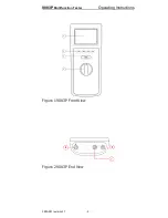
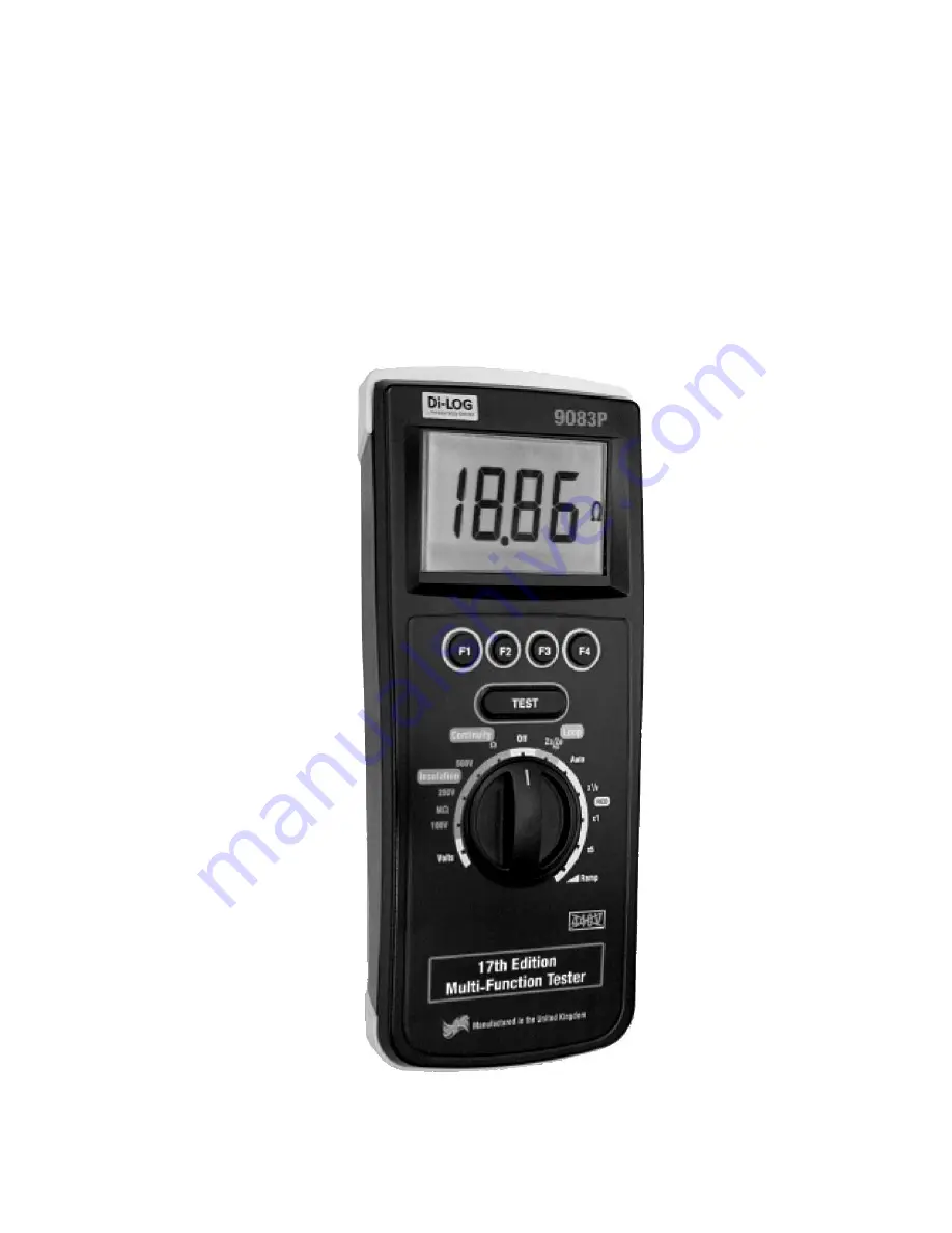
Page 2: ...9083P Multifunction Tester Operating Instructions 328A561 revision1 1 2 Figure 1 9083P Front View Figure 2 9083P End View ...

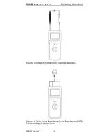
Page 3: ...9083P Multifunction Tester Operating Instructions 328A561 revision1 1 3 Figure 3 Earth Continuity Insulation Measurement Figure 4 Earth Continuity Insulation Measurement using Cordless probe ...

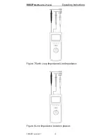
Page 4: ...9083P Multifunction Tester Operating Instructions 328A561 revision1 1 4 Figure 5 Voltage Measurement using test probes Figure 6 Earth Loop Impedance Line Impedance RCD Mains Voltage Measurement ...

Page 5: ...9083P Multifunction Tester Operating Instructions 328A561 revision1 1 5 Figure 7 Earth Loop Impedance Line Impedance Figure 8 Line Impedance between phases ...

Page 6: ... this edition may be multiplied or made public in any form or manner either electronically mechanically by photocopying recording or in any manner without prior written consent from DI LOG This also applies to accompanying drawings and diagrams Due to a policy of continuous development DI LOG reserves the right to alter the equipment specification and description outlined in this publication witho...

Page 7: ...Health Check 15 5 3 Continuity Tests 15 5 4 Insulation Resistance Tests 17 5 5 Voltage Measurement 18 5 6 Earth Loop Impedance Line Impedance 18 5 7 Auto RCD Test Sequence 19 5 8 RCD Trip Time Tests 21 5 9 RCD trip current Ramp Tests 23 6 Electrical Specifications 25 6 1 Earth Continuity 25 6 2 Insulation Resistance 25 6 3 Earth Loop Impedance 25 6 4 Line Impedance 26 6 5 RCD 26 6 6 Voltage Freque...

Page 8: ...r measurement control and laboratory use Part 1 General requirements BS EN 61557 1 2 3 4 6 10 1997 Electrical safety in low voltage distribution systems up to 1000V a c and 1500V d c Equipment for testing measuring and monitoring of protective measures BS EN 61326 1998 Electrical equipment for measurement control and laboratory user EMC Requirements Performance The instrument operates within speci...

Page 9: ...me at I n I n and 5xI n RCD Trip current Earth Loop Impedance Prospective Fault Current Mains Impedance Prospective Short circuit Current Power socket wiring polarity 1 Important Information These operating instructions are intended for the use of adequately trained personnel The following symbols are used in these operating instructions and on the 9083P Caution risk of electric shock Instructions...

Page 10: ...o earth Always hold test probes above the hand guards The 9083P and all associated cables and leads must be checked for signs of damage before equipment is operated Prior to any resistance measurement always ensure that the circuit under test is electrically isolated Where safe operation of the 9083P is no longer possible it should be immediately shut down and secured to prevent accidental operati...

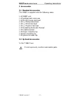
Page 11: ...3P unit 1 off professional carry case 1 off Di LOG mains test lead 1 off 1 2 M black test lead 1 off 1 2 M red test lead 1 off 1 2 M green test lead 1 off Operating Instruction Manual 1 off Leadless probe 1 off black crocodile clip 1 off red crocodile clip 1 off green crocodile clip 3 2 Optional Accessories 3 15A T 500V Fuse Do not open unit no other serviceable parts ...

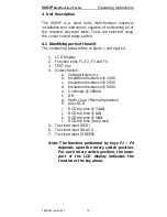
Page 12: ...isplay 2 Function keys F1 F2 F3 and F4 3 TEST key 4 Rotary Switch a Voltage frequency b Insulation resistance 100V c Insulation resistance 250V d Insulation resistance 500V e Continuity 200mA f Off g Earth Loop Mains Impedance h Auto RCD i RCD trip time I N j RCD trip time I N k RCD trip time 5I N l RCD trip time ramp test 5 Test lead input RED 6 Test lead input BLACK 7 Test lead input GREEN Note ...

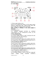
Page 13: ...cate the test measurement for the active test type 4 Icons for function key F1 These icons are used to display the available options for the selected test Repeatedly pressing function key F1 cycles through the available options 5 Icons for function key F2 These icons are used to display the available options for the selected test Repeatedly pressing function key F2 cycles through the available opt...

Page 14: ...CD test icons These icons display the selected RCD test function 10 Warning Icons These icons are used to inform the user of the potential of any hazard or warning which may restrict the operation of the 9083P Note The 9083P is equipped with a thermal cut out to protect against damage from excessive internal temperature If the thermal cut out is activated the HOT icon is illuminated and all RCD an...

Page 15: ...ng continuity tests If the test probes are connected across a voltage of 30V then the 9083P will automatically display the voltage between the probes the warning buzzer will sound and the TEST key is inhibited Rotate the rotary switch until the Ω test is selected When the continuity test is selected the 9083P will display the available test options for 1 second Buzzer Test Lock Lead Zero If the Bu...

Page 16: ...All subsequent measurements will take into account the test lead resistance compensation until the function is disabled by pressing function key F3 Note A maximum test lead resistance of 10 ohms can be nulled out If the test lead resistance is great than 10 ohms an error beep will indicate that the Lead Zero function has failed Note For ease of use the 9083P will store the lead compensation when t...

Page 17: ...st Lock F2 The Test Lock is used to lock the instrument in a continuous measurement mode with a single press of the TEST key When Test Lock is enabled the LCD shows the padlock icon When Test Lock is active the TEST key is locked until the option is disabled or the rotary switch is moved to another position To enable the Test Lock mode test press the TEST key and F2 simultaneously To disable Test ...

Page 18: ...not illuminated Rotate the rotary switch until the Zs test is selected Press the function key F1 to select either the Earth Loop Impedance test L PE or the Line Impedance test L N F1 F2 F3 F4 Line Impedance Not used Not used Not used The secondary display will automatically show the appropriate icon PFC when L PE is selected and PSC when L N is selected Note When the Zs switch position is selected...

Page 19: ...e need to repeat the test 5 7 Auto RCD Test Sequence The 9083P will only allow the Earth Loop Impedance test to be performed if the correct voltages are detected between phase neutral PN illuminated phase earth PE illuminated and neutral earth NE not illuminated Leakage currents or voltage on the protective conductor may influence the measurement The Auto RCD test is used to automatically perform ...

Page 20: ...current selective RCD dc current standard RCD dc current selective RCD RCL F3 The RCL Recall key is used to recall the results of the last automatic RCD test performed by the 9083P The LCD will update to show all of the relevant parameters for the result displayed Continue to press the F3 key to rotate through the results I n test current 0o I n test current 180o I n test current 0o I n test curre...

Page 21: ...primary display When the sequence is completed the RCL key F3 is used to recall the measurements 5 8 RCD Trip Time Tests The 9083P will only allow the Earth Loop Impedance test to be performed if the correct voltages are detected between phase neutral PN illuminated phase earth PE illuminated and neutral earth NE not illuminated Leakage currents or voltage on the protective conductor may influence...

Page 22: ... All RCD tests will start on zero crossing AC DC Selective Function key F2 is used to select the required RCD type AC or DC sensitive combined with standard or selective RCD types Each time the F2 key is pressed the next option is selected During selective tests the 9083P will display a delay timer which counts down from 30s to 0s Pressing the Test key or turning the rotary switch while the 9083P ...

Page 23: ...edance test to be performed if the correct voltages are detected between phase neutral PN illuminated phase earth PE illuminated and neutral earth NE not illuminated Leakage currents or voltage on the protective conductor may influence the measurement Note The 9083P will first perform a short pre test to determine the fault voltage that may appear on the protective conductor during the test If the...

Page 24: ...ected During selective tests the 9083P will display a delay timer which counts down from 30s to 0s Pressing the Test key or turning the rotary switch while the 9083P is counting will terminate the count Rated residual operating current I n F4 The rated residual operating current is selected by pressing the F4 key 10mA 30mA 100mA 300mA 500mA 0o 180o F1 Use the F1 key to alternate between the starti...

Page 25: ...tance Test Voltage Accuracy 0 20 open circuit Test current 1mA into UN x 1000Ω V Test Current Short Circuit 2mA Display Range 0 05MΩ 199MΩ Measuring Range 0 05MΩ 1 99MΩ 2 0MΩ 19 9MΩ 20MΩ 100MΩ Resolution 0 01MΩ maximum Accuracy 5 5 digits Voltage Indication Accuracy 5 Number of repeat tests Approx 3000 6 3 Earth Loop Impedance Supply Voltage 195V 253V 45Hz 65Hz Nominal Test Current 15mA Display Ra...

Page 26: ...Voltage 195V 253V 45Hz 65Hz Nominal Test Currents 10mA 30mA 100mA 300mA 500mA Test Current Accuracy 0 10 at I n and 5I n 10 0 at I n Trip Time Ranges 0ms 2000ms I n 0ms 300ms I n General 0ms 500ms I n Selective 0ms 40ms 5I n Trip Time Accuracy 5 2 digits Ramp Current Range I n to 1 1 I n Trip Current Measurement Accuracy 10 6 6 Voltage Frequency Measurement Display Range 0V 440V Voltage Measuring ...

Page 27: ...0 300V Category III Pollution degree 2 according to IEC 61010 1 Protective system IP40 according to IEC 60529 Electromagnetic compatibility EMC Interference immunity and emitted interference conforming to IEC 61326 1 Operating temperature range of 0 C to 40 C without moisture condensation The 9083P can be stored at any temperature in the range 25 C to 65 C relative humidity up to 90 The batteries ...

Page 28: ...nect all of the test leads from the unit 8 2 Securing the 9083P Under certain conditions safe operation of the 9083P can no longer be assumed Visible damage of the instrument case Incorrect measurement results Recognisable abuse to the instrument due to prolonged storage under improper conditions Recognisable abuse to the instrument due to extraordinary transportation stress Check the battery comp...

Page 29: ... a dry cloth 8 4 Battery Replacement Before removing the battery cover ensure that the 9083P is electrically isolated from any potential voltage source Power the unit off by selecting the Off position on the rotary switch Disconnect all the test leads from the unit Position the 9083P face down and release the captive screw in the battery compartment cover Remove the battery compartment cover Remov...

Page 30: ... Remove the battery compartment cover Lift one end of the fuse out of the fuse holder with the help of a flat bladed screwdriver Lift the defective fuse completely out of the fuse holder Insert a new fuse of the correct type as described and specified by the text on the battery compartment cover Ensure that the new fuse is seated and centred in the fuse holder Relocate the battery cover over the b...

Page 31: ...codile clips 44B151 Mains test lead 44B152 Cordless Probe 43B721 Carrying Case 328A953 3 15A T 500V 1 27B083 For help or advice on Service and Calibration contact Service Department Di LOG Test Equipment 28 Wheel Forge Way Trafford Park Manchester M17 1EH Freefone 0800 018 9122 Freefax 0800 018 6711 Email sales dilog co uk web dilog co uk ...

Reviews: