

Rev D August 2017
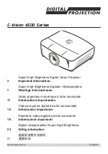
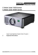
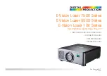
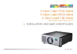
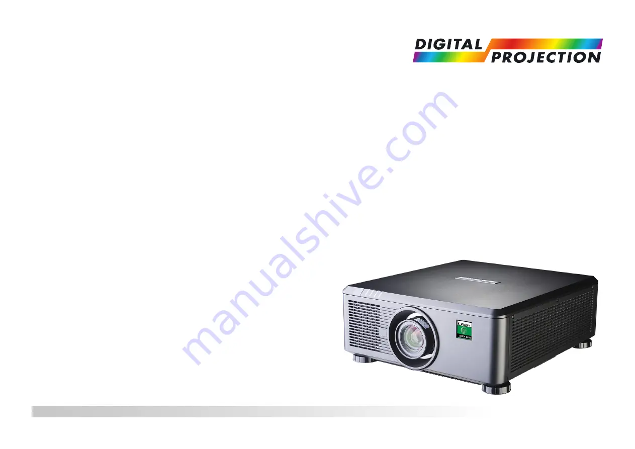
E-Vision Laser 7500 Series
E-Vision Laser 8500 Series
E-Vision Laser 10K Series
High Brightness Digital Video Projector
INSTALLATION AND QUICK-START GUIDE
4
117-919D
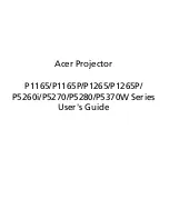
The Digital Projection E-Vision Laser 10K Series offers stunning visual experiences with its advanced laser technology. Ensure a seamless installation and quick start with the provided Installation and Quick Start Manual. Download this comprehensive manual for free from our website to optimize your product experience.
Rev D August 2017
E-Vision Laser 7500 Series
E-Vision Laser 8500 Series
E-Vision Laser 10K Series
High Brightness Digital Video Projector
INSTALLATION AND QUICK-START GUIDE
4
117-919D