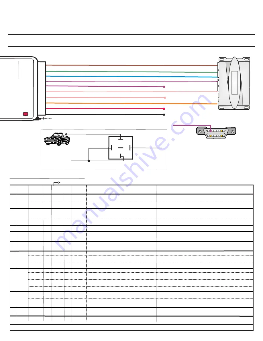
SEE WIRE CONNECTION GUIDE FOR DETAILED INFORMATION REGARDING WIRE FUNCTIONALITY
Section A
Red
Orange
Green
Blue
Violet
Black
Violet/White
Pink
Pink/White
Chassis Ground
(+)12 Volt Constant
Trunk or Disarm Input (See Wire Connection Guide)
Aux1 (See Wire Guide)
Aux 2 (Wire acts as Input or Output depending on vehicle type. See Wire Guide)
Door Sense Trigger
Unlock
Programming Button
Lock
Brown
Ground When Running
LED
10
PIN
HARNESS
INPUT
INPUT
INPUT
INPUT
INPUT
INPUT
IN/OUT
DATA
INPUT
OUTPUT
(-)
(+)
(-)
(-)
(-)
(-)
(+/-)
(-)
(-)
Data (see FIG 2)
Fig. 2: DATA WIRE
CONNECTION
Data Wire Connects to OBDII PIN 2
Section B
Upgradeable
V
ehicle
Interface
Module
Door
locks/
Data
Override
GM
Passlock
2/GM
Passkey
3
OEM
Alarm
REMO
TE
RC
S
SY
STEM
WIRE GUIDE: CONNECTIONS
30
86
85
87
To Pink/White Wire
RELAY WIRING FOR WINDOWS ROLL-UP OPTION
To Brown Vehicle Accessory Wire
12 Volts
Fig. 1: TYPE 4 ONLY
LEGEND:
RCS = Remote Control System
N/C = No Connection
N/A = Not Applicable W2W= analogue wire to wire
D2D= data 2 data
(-)
/(+)
(-)
(-)
Input
Input
Input
Input
Input
Data
I/O
STATUS
WIRE
COLOR
Brown
Green
Blue
Violet/
White
Violet
Pink/
White
Pink
Orange
Red
Black
(-)
(+)
SPECIFIC WIRE CONNECTION LOCATION
Constant (+) 12 Volt Source
Chassis Ground
Connect
Location
RCS
Vehicle
Vehicle
Vehicle
(-)
ACTIVATION and/or FUNCTIONALITY
-Locks All Doors
-Window Roll-Up Feature: Activated with 2ND press of aftermarket remote
(See User Settings, MODE 5)
Unlocks All Doors
(See User Setting, MODE1)
RCS
RCS
Power Source
Ground Source
Data Commands from Module to Vehicle
PIN
1
2
3
4
5
6
7
8
9
10
Ground When Running Output of Remote Starter
Ground When Running Output of Remote Starter
D2D
w2w
10 PIN HARNESS
Lock Output wire
Unlock Output wire
Door Sense Trigger Input wire
Detects Door status (Open/Close) via data bus:
then converts to an analogue output (-)
Output
(-)
RCS
Input
Input
(-)
(-)
RCS
RCS
D2D = Optional use of 4 Pin Data to Data (D2D) cable will replace the analogue wire (w2w) connection
Connect to Vehicle’s Brown Accessory Wire
AUX 2 Output
N/C
Output
Input
N/C
(-)
(-)
N/C
Vehicle
RCS
N/C
Window Roll-Up (Relay Required, See Fig. 1)
1sec. (-) Pulse Left Sliding Door Open/Close
(See User Settings, MODE 3)
N/C
w2w
D2D
w2w
D2D
w2w
Input
Input
Input
(+/-)
(-)
(-)
Vehicle
RCS
RCS
Connect to Domelight (2 Door Vehicle N/A)
AUX 1 Output
AUX 1 Output
Domelight = Rear Door Detection
Opens Fuel Door
1 sec. (-) Pulse Right Sliding Door Open/Close
(See User Settings, MODE 2)
(See User Settings, MODE 2)
Disarm Output
Trunk Release Output
Connect if vehicle does not disarm upon remote start
Trunk Release
VEHICLE
TYPE
1 to 4
5 to 7
OEM Security Arm/ Immobilizer D Heated Seats at 32ºF (0ºC)
OEM Security Arm/ D Heated Seats at 32ºF (0ºC)
1 to 5
All Types
Input
(-)
RCS
On Board Diagnostic Connector (OBDII) PIN 2
(See Fig.2)
All Types
Type 4
Type 7
1,2,3,5,6
D2D
w2w
w2w
D2D
w2w
N/C
1 & 4
Type 2
Type 7
1, 4 & 5
2,3,6 & 7
All Types
All Types
All Types
3,5 & 6
N/C
N/C
N/C
N/C
N/C
N/C
Lock Output wire
RCS
(-)
Input
D2D
w2w
6 to 7
Locks All Doors
D2D
w2w
D2D
w2w
D2D
w2w
D2D
w2w
D2D
w2w
D2D
w2w
D2D
w2w
D2D
w2w
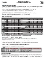
1700G1
Description:
Functions:
American Door Lock Interface & GM Immobilizer Override
Lock/Unlock, Driver's Priority Unlock, Trunk/Hatch, Sliding Door Left & Right , OEM Security Alarm Arm/Disarm, Data to Analogue
Door Trigger Output (-)
Override GM Passkey3 Transponder Immobilizer & Passlock 2 Immobilizer via data bus
GM ONLY:
Installation
Manual
(1\3 Pages)
AMERICAN DOOR LOCK INTERFACE
& GM IMMOBILIZER OVERRIDE XK01-AMDL
IMPORTANT!
Please read this installation guide thoroughly before installing the 1700G1. Use only a high quality digital multi-meter for testing. This product connects to the vehicle's low
voltage signal wire and improper installation or testing can result in damage to the vehicle. Never use a test light or logic probe to test wires in this vehicle!


