background image


DJI L1 Operation Guidebook 


V1.1 (June-2022) 


Summary of Contents for ZENMUSE L1

Page 1: ...DJI L1 Operation Guidebook V1 1 June 2022 ...

Page 2: ...2 2 IMU Calibration in Mapping Oblique Linear Flight Missions 14 3 2 3 IMU Calibration in Waypoint Flight Missions 15 3 3 RGB Camera Recalibration 16 3 3 1 Calibration data collection 16 3 3 2 Use DJI Terra software to generate the calibration files 17 3 3 3 Run the calibration files in L1 18 3 3 4 How to restore factory parameters 18 3 4 Flight Mission Planning 19 3 4 1 Topographic Surveying 19 T...

Page 3: ...raw data is missing or the file path is wrong 45 4 4 3 Error Message The raw data of the LiDAR point cloud is abnormal 46 4 4 4 Error Message LiDAR point cloud accuracy optimization failed 46 4 4 5 Error Message LiDAR point cloud POS calculation failed 46 4 4 6 Issue Quality of point cloud model is poor or the result has severe data loss 46 4 4 7 How to achieve a good vertical accuracy 47 ...

Page 4: ...e firmware updates M300 RTK Aircraft V04 00 03 00 M300 RTK Remote Controller V04 00 03 00 Pilot App V4 0 1 21 Zenmuse L1 V04 00 01 06 DJI Terra V3 1 4 Note The parameters provided in this guidebook are for reference only and do not apply to all scenarios Please adjust them as appropriate to suit the actual conditions 2 Parameter Overview 2 1 Introduction to DJI L1 The Zenmuse L1 integrates a Livox...

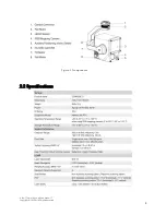
Page 5: ...http www dji com zenmuse l1 Copyright 2022 DJI All Rights Reserved 5 Figure L1 components 2 2 Specifications ...

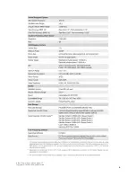
Page 6: ...http www dji com zenmuse l1 Copyright 2022 DJI All Rights Reserved 6 ...

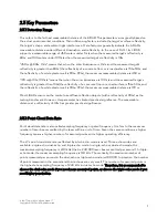
Page 7: ...is 90 99 the maximum measurable distance is 190 m Most LiDAR sensors on the market use diffuse reflection objects with a reflectivity of 90 as the testing benchmark However this parameter has limited practical significance The measurable distance at a reflectivity of 10 has greater practical significance 2 3 2 Point Cloud Data Rate Point cloud data rate is also called sampling frequency or pulse f...

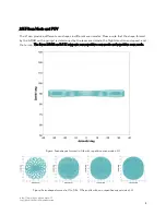
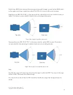
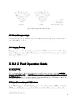
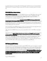
Page 8: ... that the shape formed by the LiDAR on the ground is determined by the laser scan mode the flight direction and speed and the terrain The Livox LiDAR on DJI L1 supports non repetitive scan mode and repetitive scan mode Figure Scan shapes formed in 0 1s with repetitive scan mode of L1 Figure Scan shapes formed in 0 1s 0 2s 0 5s and 1s with non repetitive scan mode of L1 ...

Page 9: ...e is recommended for high accuracy surveying and mapping Figure Scan angle in repetitive scan mode Non repetitive scan FOV 70 4 77 2 In this scan mode the vertical FOV is wider This mode is recommended for data capturing of complex structures such as building facades Figure Scan angle in non repetitive scan mode Note The effective range of L1 varies based on where the object is within the FOV The ...

Page 10: ...does not represent the accuracy of the final result 3 DJI L1 Field Operation Guide 3 1 RTK PPK For the purpose of point cloud data processing L1 needs to have centimeter accurate positioning data with either RTK or PPK The RTK FIX status needs to be maintained throughout the duration of the L1 flight mission If RTK connection stability cannot be guaranteed PPK could also be used The detailed workf...

Page 11: ...e station you can connect the aircraft to the D RTK 2 for the flight mission Alternatively you can use the PPK method where no real time connection between the drone and the D RTK 2 is required With the PPK method the distance between the D RTK 2 and the aircraft is recommended to be within 10km Select None in the RTK service type Turn off the RTK Positioning switch to go to GNSS flight mode After...

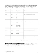
Page 12: ...e deleted Data format Version Message Rename to Rinex V2 1 x DJI_YYYYMMDDHHMM_XXX obs V3 0 x RTCM V3 0 1003 1004 1012 1014 DJI_YYYYMMDDHHMM_XXX rtcm V3 2 MSM4 MSM5 MSM6 MSM7 OEM OEM4 RANGE DJI_YYYYMMDDHHMM_XXX oem OEM6 RANGE UBX RAWX DJI_YYYYMMDDHHMM_XXX ubx Table RTK protocol types supported by L1 Note Base station files are necessary for L1 data processing If neither Ntrip nor PPK files exist L1...

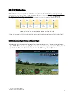
Page 13: ...ure the inertial navigation system accuracy Figure IMU calibration is needed before during and after the flight Below are two ways of IMU calibrations that can be used during manual mission flight route flight 3 2 1 Calibration Flight Button in Manual Flight Fly the drone to a proper altitude switch to the camera screen and click on the Calibration Flight button M300 RTK will automatically fly for...

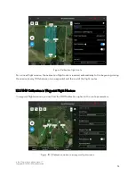
Page 14: ... Linear Flight Missions In mapping oblique flight missions you can find the toggle IMU Calibration When turned on acceleration and deceleration calibration flights will be inserted to the flight route at the starting point the ending point turning points and along the route every 100s The calibration routes are shown in yellow in the figure below ...

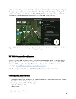
Page 15: ...on flight route is inserted automatically to the beginning during the mission every 100s between two waypoints and the end of the flight routes 3 2 3 IMU Calibration in Waypoint Flight Missions In waypoint flight missions you can find the IMU Calibration option in the route parameters Figure IMU Calibration option in a waypoint flight mission ...

Page 16: ...oint 1 and finish at Waypoint 5 3 3 RGB Camera Recalibration When the L1 has regular colorization issues such as multiple lines appearing in the point cloud with ghosting effect the user will need to recalibrate the internal and external parameters of the RGB camera of L1 following the below steps Before you start please check your firmware versions referring to Section 1 Supported Firmware and So...

Page 17: ...ed for calibration 3 3 2 Use DJI Terra software to generate the calibration files Use DJI Terra version 3 1 0 or above to create a new LiDAR Point Cloud Processing reconstruction mission Import the dataset collected by defining the dataset directory and changing the Scenarios option to Zenmuse L1 Calibration Start processing in Terra When the reconstruction is completed please check if the point c...

Page 18: ...le with suffix txt the calibration process is successful if the log file shows all succeed Figure The txt file will show all succeed if the calibration is successful 3 3 4 How to restore factory parameters In case you need to restore the factory parameters of the L1 sensor please follow below steps Create a new txt text file and name it as reset_cali_user Open the file and write the SN serial numb...

Page 19: ... file is restored to the factory time 3 4 Flight Mission Planning A flight mission of the survey area can be pre planned with the DJI Pilot App to enable automatic data capture of a polygon area or a strip area Detailed parameter recommendations for typical scenarios are as below 3 4 1 Topographic Surveying This is a typical scenario of LiDAR to generate topographic maps contour lines etc It may a...

Page 20: ...parameters should be set based on it IMU Calibration Enabled Altitude Mode Relative to takeoff point ALT is usually selected by default ASL EGM96 could be selected if you need to plan the mission with EGM96 altitude Flight Route Altitude The recommended flight altitude is 50 100 meters When the ground object s reflectivity is 10 the L1 s measurable distance is 190 meters The flight altitude should...

Page 21: ...val Shots Payload Settings Echo Mode and Lidar Sample Rate Triple Echo 160kHz can be used for better penetration Dual Echo 240kHz can be used for maximum points Scan Mode Repeat RGB Coloring On How to enable Terrain Follow Mission Terrain follow Flight DJI L1 supports terrain follow flight for waypoint mapping and corridor flight plans With the DJI Pilot app to perform a precise terrain follow fli...

Page 22: ...c coordinate system file and not a projected coordinate system file Otherwise the imported file may not be recognized It is recommended that the resolution of the imported file should be no more than 10 meters Importing Files 1 Enable Terrain Follow and IMU Calibration in Mapping mission 2 Tap Select DSM File tap select and import the file from the microSD card 1 Prepare the DSM file of the survey...

Page 23: ...D data of the target area and perform 2D reconstruction in DJI Terra with Fruit Tree mode A gsddsm tif file will be generated in the map folder of the mission files It can be imported to DJI Pilot App for terrain follow Figure Fruit Tree mode Low Resolution need to be selected in Terra ...

Page 24: ...o download the terrain elevation data from an open database such as SRTM 2 Import the DSM file to DJI Pilot App Terrain Follow and IMU calibration flight options can be enabled at the same time Figure Terrain Follow Option in DJI Pilot App You can put the DSM file in a SD card and insert it to the RC Then click on Select DSM File and select the DSM file in the SD card ...

Page 25: ... area within this area Terrain Follow is recommended when the elevation difference of the survey area is greater than 100 meters 3 4 2 Riverbank Road Surveying When the survey area is a narrow strip of land such as roads railways riverbanks etc Linear Flight Mode can be used for L1 mission planning Category Parameter Name Explanation and recommended value General Camera type Zenmuse L1 LiDAR Mappi...

Page 26: ...cloud density should be determined first based on the project requirements Then the flight speed and other parameters should be set based on it Flight Band Left Right extension length Can be adjusted based on the width of the survey area To ensure accuracy it is recommended to adjust this value to have at least 3 flight routes covering one band Flight band cutting distance As default Flight Band P...

Page 27: ...d can be adjusted according to the desired point cloud density 8 12 m s is recommended IMU Calibration Enabled Photo Mode Timed Interval Shot Flight Route Advanced Settings Side Overlap Recommended to be at least 50 3 4 3 Powerline L1 can be used to collect the point cloud data of transmission lines and the power pylons As there are undulations in the power line corridor the recommended workflow i...

Page 28: ...rrent point by pressing the C1 button Figure View from the top of a power pylon to record a waypoint you can adjust the gimbal to be 90 and adjust the aircraft position 3 Repeat this action for all structures within the mission area 4 Save the mission 5 Edit the mission parameters according to the table below Category Parameter Name Explanation and recommended value Genera settings Gimbal Zenmuse ...

Page 29: ...ion Return to Home by default Waypoint settings First waypoint Add an action Gimbal Pitch Rotation and set the degree to be 90 Add an action Timed Interval Shot and Start point cloud modeling recording Last waypoint Add an action Finish point cloud modeling recording L1 payload settings in the MENU button Sampling Rate 240 kHz Scanning Mode Non repetitive Return Mode Dual RGB Coloring On ...

Page 30: ...upported for L1 data in Terra Figure Example of normal photogrammetry checkpoints not recommended for LiDAR as you cannot tell the center of it in reflectivity mode Two types of checkpoints are recommended for LiDAR as shown below 3 5 1 3D Checkpoints L1 point clouds can be displayed in reflectivity mode Therefore if the checkpoints are marked with significant differences in reflectivity they can ...

Page 31: ...the field the white paint is highly reflective while the black paint is non reflective Figure Checkpoints shown in the point cloud left RGB right reflectivity In addition if there are objects with sharp reflectivity differences in the survey area such as a zebra crossing they can be also used as checkpoints ...

Page 32: ...k feature is based on the assumptions that the horizontal accuracy of the LiDAR system can be neglected and the points near the checkpoint are all on the same elevation plan Therefore it is recommended to set up the elevation checkpoint on a flat surface of at least 1m 1m in size The checkpoints should be evenly distributed in the survey area and have differences in elevation rather than all being...

Page 33: ...rompt appears 3 6 2 Flight Mission Execution If the IMU Calibration feature is enabled in the mission settings the drone will automatically perform IMU calibration by performing a shuttle flight No data will be collected during the calibration During the flight you can switch between Camera LiDAR and SBS side by side view by pressing on the left side option If the flight mission is paused and then...

Page 34: ...Rights Reserved 34 Figure automated flight screen LiDAR view Figure automated flight screen SBS view 3 6 3 Manual Data Collection When you need to collect L1 data of building facades powerlines or other complex structures manual flight is also an option ...

Page 35: ...ions Point Cloud Record Fly the drone near the target area and adjust the gimbal to a proper angle for data collection Then click on the liDAR option on the left side of the viewer to go to the point cloud screen and click the point cloud recording button to start recording During manual flight we recommend a speed of 5 12 m s and a distance from the subject of 50 100 meters During the manual flig...

Page 36: ... MNF visual data which is currently omitted with no impact RTB RTK base station data RTK RTK main antenna data RTS RTK sub antenna data and RTL rod arm data If model coloring is enabled there will also be JPG files photo data Figure Example of a test data folder and its contents If the RTB file is missing it is because the RTK was not connected or was disconnected during the flight Please refer to...

Page 37: ...loud Accuracy When enabled DJI Terra will optimize point cloud data collected at different times during processing for higher overall consistency This is a premium feature included in DJI Terra Pro and more advanced versions Each L1 comes with a 6 month license for the Electricity version You can find the license information in the package Note With the complimentary DJI Terra license you can only...

Page 38: ... that contains the data files In this way you will get only one LAS file Alternatively you can select multiple L1 data file folders for processing Then you will get a LAS file for each folder 3 Select Point Cloud Density Three density levels are available high medium and low corresponding to 100 25 and 6 25 of the point cloud data for processing Point cloud density only affects the number of resul...

Page 39: ... settings The Default setting is ellipsoidal height You may change it to EGM96 height or other options 5 Parameter Settings Point cloud effective distance The cloud points with a distance greater than the set value from the LiDAR emission center will be filtered out during post processing The default value of this parameter is 250 meters Do not set it too low or most of the points will be filtered...

Page 40: ...andard format of airborne LiDAR output will be selected by default You can also choose to output the point cloud in PLY for MeshLab PCD for CloudCompare or S3MB for SuperMap format 7 Start Processing Click Start Processing to start reconstruction During processing you can click Stop to pause the process and the software will save the current progress If you resume the process the software will con...

Page 41: ...their true colors Intensity Display the result based on the reflectivity received by the LIDAR The reflectivity is graded on a scale of 0 255 where 0 150 corresponds to diffuse reflection objects with a reflectivity of 0 100 and 151 255 corresponds to total reflectivity objects Since light reflected by the same object may be received by the LiDAR at different angles the reflectivity values of the ...

Page 42: ...http www dji com zenmuse l1 Copyright 2022 DJI All Rights Reserved 42 Figure Interpretation of LiDAR point cloud report parameters ...

Page 43: ... to the total number of points in each echo and the scan angle _sbet out The post processing trajectory file of the mission which records the trajectory information after adjustment and solution The file can be imported into third party software for trajectory display During DJI Terra s data processing the point cloud accuracy optimization function is an adjustment process For this reason you don ...

Page 44: ...ytes y body acceleration meters second double 8 bytes z body acceleration meters second double 8 bytes x body angular rate radians second double 8 bytes y body angular rate radians second double 8 bytes z body angular rate radians second double 8 bytes Table Interpretation of SBET file parameters _smrmsg out Post processing precision file It contains the root mean square error of the smoothed posi...

Page 45: ...s Table Interpretation of SMRMSG file parameters 4 4 FAQ 4 4 1 Error Message The LiDAR point cloud POS data is abnormal Possible cause The RTK was disconnected during the flight or there was no RTK base station data available or L1 was static hovering in the air during data collection Currently DJI Terra doesn t support post processing of data collected by a drone sitting still on the ground 4 4 2...

Page 46: ...a 4 4 6 Issue Quality of point cloud model is poor or the result has severe data loss 1 Poor inertial navigation accuracy Data collection started before the inertial navigation system completed warmed up or IMU calibration not performed correctly 2 Poor POS accuracy The RTK was not fixed the RTK base station was moved or the coordinate systems of the self built base station and multiple RTK base s...

Page 47: ...known point if you are using D RTK 2 make sure that you have considered the length of D RTK 2 from bottom to top of antenna it s 1 8 m if the rod is fully extended to the ground When setting the known coordinate and elevation in Pilot app make sure to use WGS84 and ellipsoid height in unit m Restart the M300 and D RTK2 when there is a base station position change error in Pilot app You may need to...

Reviews: